492 IEEE MICROWAVE AND WIRELESS COMPONENTS LETTERS, VOL. 11, NO. 12, DECEMBER 2001
A Dual-Beam Asymmetrically Scanning Leaky-Wave
Antenna by Utilizing a HEMT Resistive Upconverter
Chien-Jen Wang, Member, IEEE, Yu-Hau Sheu, and Christina F. Jou
Abstract—A dual-beam asymmetrical scanning microstrip
leaky-wave antenna (LWA) has been demonstrated in this paper. A HEMT resistive upconverter output is connected to one terminal of the LWA, and a local oscillator (LO) signal is connected to the other terminal. In this experiment, we set the LO frequency at 9.5 GHz so that the right beam is fixed at 48 . By changing the IF frequency from 0.7 GHz to 1.5 GHz, the module of the LWA can steer the left main beam of the far-field pattern from 136 to 158 (the total scanning angle of 22 ). Comparisons between the measured and theoretical results indicate that the design can achieve the asymmetrically scanning capability and agree well over the tuning bandwidth of 0.8 GHz.
Index Terms—Dual-beam asymmetrically scanning, resistive
up-converter.
I. INTRODUCTION
M
ICROSTRIP leaky-wave antennas [1]–[4] have theadvantages of narrow beamwidth, small size, easy fabrication, easy matching, frequency scanning, and can be easily integrated with other useful circuits (such as an amplifier [1], a VCO [2], a switch circuit [3]) on the same substrate to be used in communication systems. Recently, some researches have successfully achieved dual-beam symmetrically scanning capability [2]–[4]. However, in many physical applications such as position calibration systems, one beam is fixed at some angle, and the other beam needs to be steered to locate a spec-ified object with relative position to the observer. Traditional dual-beam scanning antennas fail to meet the requirement in these applications.
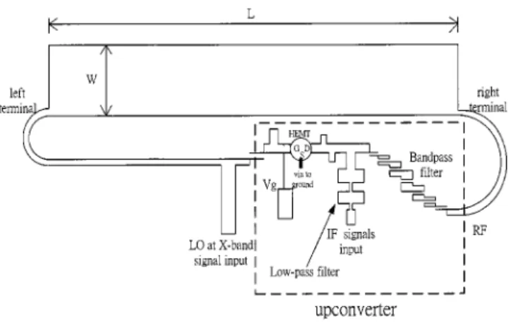
This paper details the design of a two-terminal leaky-wave antenna [2] integrated with a HEMT resistive upconverter (see Fig. 1). If the IF port has no injection, the proposed topology can perform the conventional dual-beam symmetrically scan-ning function just by changing the LO frequency. In addition, fixing the LO frequency and varying the IF frequency, we can derive the dual-beam asymmetrically scanning radiation pat-terns.
Manuscript received May 29, 2001; revised September 19, 2001. This work was supported by the National Science Council, Taiwan, R.O.C., under the Grant “Research and Study of the Smart Internal Antenna Array for the 3G Mobile Communication System.” The review of this letter was arranged by Associate Editor Dr. Ruediger Vahldieck.
C.-J. Wang is with the Department of Electrical Engineering, Feng-Chia Uni-versity, Taichung, Taiwan, R.O.C.
Y.-H. Sheu is with the R&D Department, New Elite Technologies, Inc., Hsinchu, Taiwan, R.O.C.
C. F. Jou is with the Department of Communication Engineering, National Chiao-Tung University, Hsinchu, Taiwan, R.O.C.
Publisher Item Identifier S 1531-1309(01)11121-9.
Fig. 1. Configuration of a two-terminal feeding leaky-wave antenna integrated with a resistive HEMT upconverter.
II. DESIGN
Fig. 1 shows the configuration of the X-band dual-beam asymmetrically scanning leaky-wave antenna. The circuit consists of a -type power divider, a HEMT upconverter and a microstrip leaky-wave antenna with a two-terminal feeding structure. All components mentioned above are fabricated on a RT/Duroid substrate with the thickness of 0.508 mm
and the dielectric constant of . A NEC NE42484C
low-noise HEMT serves as a frequency-mixing device of the upconverter. The HEMT device is chosen for the consideration of lower noise performance and better conversion gain in comparison with a diode [5]. Additionally, the device also has the advantages of low cost and well integration with monolithic IC (MIC) in the future.
To excite the first higher order mode, the leaky-wave antenna is fed asymmetrically. The geometry and coordinate system for the microstrip LWA are shown in Fig. 2. Both of the RF and LO signals radiate the same field as a magnetic dipole with the
magnetic current density . In order to realize the
radiation characteristics of the microstrip LWA, we analyzed its
normalized complex propagation constant of the
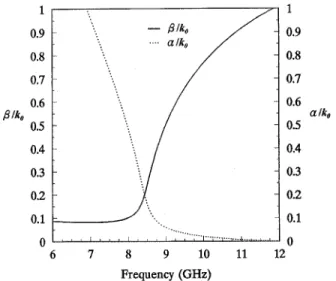
first higher order mode in the radiation region, where is the normalized phase constant and is the normalized attenua-tion constant. Fig. 3 shows the normalized complex propagaattenua-tion constant as a function of frequency, which was obtained by em-ploying the rigorous (Wiener-Hopf) solutions mentioned in [6]. When , the power of the input signal will leak in the form of the space wave in addition to the surface wave.
WANG et al.: A DUAL-BEAM ASYMMETRICALLY SCANNING LEAKY-WAVE ANTENNA 493
Fig. 2. Geometry and coordinate system for the microstrip LWA.
Fig. 3. Normalized complex propagation constants varied as a function of frequency.
III. THEORETICAL ANDEXPERIMENTALRESULTS
The resistive HEMT upconverter includes three ports (LO, IF, RF), where LO and IF are the input ports and RF is the output port. The LO frequency was set at 9.5 GHz (the X band). The IF frequency was varied from 0.7 GHz to 2 GHz (the UHF band). The RF output signal was obtained at the drain via the band-pass filter. The RF frequency range was from 10.2 GHz to 11.5 GHz (the X band). Fig. 4 showed the RF output power as a function of the bias voltage when the frequencies at the IF and the LO ports were 1.0 GHz and 9.5 GHz, respectively. The power of the IF and the LO was approximately 12 dBm and 0 dBm. The maximum output power at the RF port was close to dBm when the gate voltage was biased at the
range from V to V. The bandpass filter was used to
extract the RF signal and also excluded the spurious frequen-cies of (LO and IF). Fig. 5 showed the RF power as a func-tion of IF frequency when the LO power was at 0 dBm and the IF power was at 12 dBm. Fig. 6 showed the conversion loss of the HEMT upconverter when the LO power was 0 dBm at 9.5 GHz and the IF frequency was at 1 GHz. The 1dB compression point was approximately 12 dBm. Figs. 7-9 illustrated the sim-ulated and measured dual-beam asymmetrically scanning
radi-Fig. 4. Measured RF output power as a function of reverse gate bias.
Fig. 5. Measured and simulation RF output power as a function of IF frequency.
Fig. 6. Conversion loss of the HEMT upconverter.
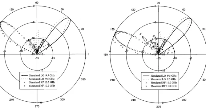
ation patterns as the LO frequency was fixed at 9.5 GHz and the RF signal was varied at the three frequencies of 10.2 GHz, 10.5 GHz and 11.0 GHz. The theoretical radiation patterns for this dual-beam asymmetrically scanning leaky-wave antenna were determined by taking the data in Fig. 4 into the electrical field in [2, eq. (1)]. The calculated angle for the right beam at the LO frequency (9.5 GHz) was 47.5 , and those for the left beam were 137 , 144 , and 156 at three frequencies of 10.2 GHz,
494 IEEE MICROWAVE AND WIRELESS COMPONENTS LETTERS, VOL. 11, NO. 12, DECEMBER 2001
Fig. 7. Dual-beam asymmetrically scanning radiation patterns for the RF signal at 10.2 GHz when the LO signal is fixed at 9.5 GHz.
Fig. 8. Dual-beam asymmetrically scanning radiation patterns for the RF signal at 10.5 GHz when the LO signal is fixed at 9.5 GHz.
10.5 GHz and 11.0 GHz for the RF signal, respectively. The maximum effective isotropic radiated power (EIRP) was close to 18.96 dBm for the right beam at 9.5 GHz and 19.96 dBm for the left beam at 10.5 GHz. The angle of the right beam was measured of 48 controlled by the operating frequency at the LO port. The left beam should scan from broadside to end-fire as the RF frequency varied from 10.2 GHz to 11.0 GHz. The scanning angles of left beams were measured of 136 , 144 and
Fig. 9. Dual-beam asymmetrically scanning radiation patterns for the RF signal at 11.0 GHz when the LO signal is fixed at 9.5 GHz.
158 (the total angle of 22 ), respectively, in accordance with the increment of the RF frequency. Good agreement between the theoretical predictions and the measured results for the pro-posed LWA performance was obtained.
IV. CONCLUSION
A novel dual-beam asymmetrically scanning leaky-wave an-tenna is illustrated in this paper. Experimental result reveals that the radiation patterns agree well with the expected patterns. The left beam scans around 22 while the right beam is fixed. The topology can provide multifunction of dual-beam symmet-rically/asymmetrically scanning patterns and is suitable for au-tomobile radar systems and satellite communication systems. We also can utilize the function of this structure to achieve cal-ibration in wireless communication systems.
REFERENCES
[1] G. J. Chou and C. K. Tzuang, “Oscillator-type active-integrated antenna: The leaky-mode approach,” IEEE Trans. Microwave Theory Tech., vol. 44, pp. 2265–2272, Dec. 1996.
[2] C. J. Wang, C. F. Jou, and J. J. Wu, “A Novel two-beam scanning leaky-wave antenna,” IEEE Trans. Antennas Propagat., vol. 47, pp. 1314–1317, Aug. 1999.
[3] C. J. Wang, C. F. Jou, and Y. C. Shih, “A beam-switchable scanning leaky-wave antenna,” Electron. Lett., vol. 36, no. 7, pp. 596–597, Mar. 2000.
[4] C. Luxey and J. M. Laheurte, “Simple design of dual-beam leaky-wave antennas in microstrips,” in Proc. Inst. Elect. Eng. Microwave, Antennas
Propagat., vol. 44, Dec. 1997, pp. 397–401.
[5] J. L. M. Lord and J. L. Fikart, “FET upconverter design using load dependent mixing transconductance,” IEEE MTT-S Dig., vol. 2, pp. 1089–1092, Dec., 1988.
[6] D. C. Chang and E. F. Kuester, “Total and partial reflection from the end of a parallel-plate waveguide with an extended dielectric loading,”