Pergamon
0957-4158 (95) 00008-9
Mechatronics Vol. 5, No. 4, pp. 441-455, 1995 © 1995 Elsevier Science Ltd Printed in Great Britain. All rights reserved. 0957-4158/95 $9.50+0.00
F U Z Z Y C O N T R O L O F R I D E R - M O T O R C Y C L E S Y S T E M U S I N G G E N E T I C A L G O R I T H M A N D A U T O - T U N I N G
J. C. WU and T. S. LIU*
Department of Mechanical Engineering, National Chiao Tung University, Hsinchu 30050, Taiwan, R.O.C.
(Received 8 July 1994; accepted 5 December 1994)
Abstract--This study investigates the stability control of a rider-motorcycle system based on fuzzy control in conjunction with both genetic algorithm (GA) and an auto-tuning method. The auto- tuning method, which entails tuning rules, is employed to on-line adjust output gains of fuzzy control. Although a G A has been used for fuzzy control in the literature, it has been confined to aiding membership functions' enaction. By contrast, this study employs a G A to determine optimal parameters in control rules for fuzzy control and in tuning rules for the auto-tuning method. Both computer simulation and experiment with regard to an inverted pendulum hinged to a rotating disk are carded out to represent the circular motion of the rider-motorcycle system, in which the inverted pendulum represents a rider's body in banking motion. The relation between riding speeds of the motorcycle and leaning angles of the rider is examined based on speed variations and Bode plots. Simulation and experimental results show the significant effect of the rider's banking angle on stability control.
I. INTRODUCTION
A rider-motorcycle system consists of a motorcycle that represents a mechanical system and a rider who perceives and steers the motorcycle. Although a motorcycle is statically unstable in nature, appropriate steering of the rider can stabilize the motorcycle during riding. Incorporating steering torque control and the rider's body control actions, Katayama et al. [1] constructed a rider model using proportional control. Liu and Wu [2] employed the fuzzy control method to investigate the performance of rider-motorcycle systems. In the current study, fuzzy control with both genetic algorithm (GA) and an auto-tuning method is proposed to improve the performance of fuzzy control that represents rider behavior. An experimental apparatus is designed and conducted to investigate how riding speeds of the motorcycle and leaning angles of the rider's body affect the stability of a rider-motor- cycle system in a circular motion. Both computer simulation and experiment are carded out. Of interest is stability control of the inverted pendulum that represents a rider's body in banking motion.
Zadeh presented the fuzzy set theory [3] and the basic concepts of fuzzy sets using a nonmathematical approach [4]. There have been many applications reported in the literature. Fuzzy control research based on the fuzzy set theory was initiated by Mamdani [5]. Yamakawa [6] used a fuzzy controller hardware system to stabilize an
*To whom all correspondence should be addressed.
442 J.C. WU and T. S. LIU
inverted pendulum. Procyk and Mamdani [7] proposed a self-organizing controller that employs a set of linguistic decision rules expressed quantitatively and mani- pulated by using the fuzzy set theory. OUero and Garc/a-Cerezo [8] developed auto- tuning methods to adjust parameters for performance improvement. Harris and Moore [9] presented a graphical analysis tool, similar to an algebraic phase plane approach, for fuzzy control system analysis.
As model-free estimators, both neural networks and fuzzy control do not require mathematical models in implementation [10]. Lee et al. [11] proposed a strategy for controlling a class of nonlinear dynamical systems based on neural networks. Essentially, neural networks can approximate arbitrary nonlinear maps when suitable learning strategies are applied. Ozaki et al. [12] present a nonlinear compensator using neural networks for trajectory control of robotic manipulators. Generally, a multilayer network is implemented in neural networks, which learn through a collection of given input-output pairs. By contrast, a fuzzy controller is endowed with control rules that are constructed based on heuristic control of experienced human operators. This study develops fuzzy control integrated with both GA and an auto-tuning method to improve the performance of fuzzy control. Hong et al. [13] proposed an auto-tuning method, which entails fuzzy rules, to adjust proportional- integral-derivative gains. By contrast, in the current study output gains of fuzzy control are on-line adjusted using tuning rules. Unlike Karr [14], who employed a GA to select membership functions, this study employs a G A to determine optimal parameters in consequences of fuzzy rules. The robust nature of GAs facilitates selecting parameters in not only control rules for fuzzy control but also tuning rules for the auto-tuning method.
The remainder of this paper is organized as follows. Section 2 constructs fuzzy control integrated with both GA and auto-tuning method. Section 3 describes GAs. In section 4, the model of an inverted pendulum hinged to the rim of a rotating disk is developed for computer simulation. The computer simulation is described in section 5. Section 6 describes experimental setup and results.
2. FUZZY CONTROL
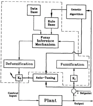
In this paper, fuzzy control is used to represent the role of a rider in steering a motorcycle. A fuzzy controller includes control rules and employs a deterministic algorithm that is essentially nonlinear and robust. A general scheme of a classical fuzzy controller as depicted in Fig. 1 includes five main parts. The rule base consists of fuzzy rules. The data base contains membership functions of fuzzy subsets. Kickert and Mamdani [15] showed that, under certain restrictive assumptions, a fuzzy controller can be viewed as a multilevel relay. In this study, fuzzy control in conjunction with both GA and an auto-tuning method as depicted in Fig. 2 is proposed, where K~ and Ko denote input and output gains. The present fuzzy control contains both coarse-tuning and fine-tuning controls. In order to improve the on-line performance of fuzzy control, the auto-tuning method includes tuning rules that are used to adjust output gains in fuzzy control. The form of tuning rules is the same as that of control rules employed in fuzzy control. Hence, the auto-tuning method entails the same inference mechanism as fuzzy control. The difference between tuning
Fuzzy control of rider-motorcycle system 443 Data Base
1 _ _
Defuzzification
L
Control
Input -I
-I
I
Rule
BaseI
F u z z yI
Inference
Mechanism
P l a n tFuzzification
+Setpolnt
Output
Fig. 1. Block diagram of classical fuzzy control system.
7
~
GeneticJ _ ~
I I A,.°,l~m I I
,,
,
,o[3;:~°~ L
',l l
I
zi(icati°nl
l
I Fuzzifi:ati°n ]!l
" '
~-~=o~L\: -~
j~
--:tJ!l
I I- - - [ - ~
~
,
_.F___JI
I I outpo~ "Fig. 2. Block diagram of fuzzy control with genetic algorithm and auto-tuning.
rules of the auto-tuning method and control rules of fuzzy control is the input and output variables. In this study, a G A is employed to select parameters in control rules for fuzzy control and tuning rules for the auto-tuning method, thereby it provides the controller with the adaptive capabilities necessary for complex systems.
The fuzzy rule is one of the ingredients for a fuzzy controller. In this study, fuzzy identification rules [16] are employed to reduce the number of required fuzzy rules
444 J.C. WU and T. S. LIU
and to adjust parameters. Accordingly, a fuzzy rule is of the form
Ri: If xl is e~il and . . and xk is - i • Ak then y, = p'oxl + " ' " + p k - t X k i + P k , i
~ i ~ i i
where A1 . . . Ak denote fuzzy sets, p~ . . . Pk crisp parameter values of the consequence determined by the G A , yi denotes variable of the consequence of the ith fuzzy rule, and x I, x~i~., xk denote variables of the premise, i.e. input variables. When the input values . . . xk are singletons, the final action y0 derived from n fuzzy rules is written as
pt E w i y i y 0 _ _ _ i = 1 ,
(1)
tl ~ w i i = 1where y ' is calculated by the consequence equation of the ith fuzzy rule and the truth value w z of the premise in the ith fuzzy rule is represented by
w ' = /~a,(x']) A . . . A /~a~(x°). (2)
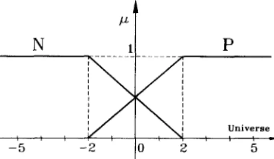
The consequence of a fuzzy identification rule in this study represents a locally linear input-output relation, in which parameters p~ of the consequence are crisp values. The fuzzy identification method reduces the number of fuzzy subsets for input variables and hence reduces the number of fuzzy rules. Furthermore, it facilitates adjustment of the crisp control value by tuning parameters in the consequences. To determine membership functions is a subjective issue and is usually performed in the knowledge acquisition domain. In this study, both input gains of fuzzy control and the number of membership functions for input variables are assumed to be constants. Membership functions of input variables are shown in Fig. 3, which comprise only two fuzzy subsets P (positive) and N (negative). Once two fuzzy subsets of input variables are fixed, the adjustment of the crisp control value can be accomplished by tuning parameters in the consequence.
3. GENETIC A L G O R I T H M
A G A is based on the technique of natural genetics and combines a Darwinian survival-of-the-fittest with a random structured information exchange. Since the
-~5 N /x
!
:
tE
- 2 0 2 P U n i v e r s eFuzzy control of rider-motorcycle system 445 natural adaptation is the fundamental theme of the GA, they can be implemented to "discover" explicit solutions. Although artificial neural networks (ANNs) in AI techniques can learn through a collection of input-output pairs, it is difficult to extract information from ANNs. By contrast, the G A not only solves problems but also offers representations of answers. The GA was originally developed by Holland [17] and has been analyzed and extended further by Goldberg [18]. Krishnakumar and Goldberg [19] employed genetic algorithms to optimize aerospace control systems. In this study, in order to improve fuzzy control, optimal values of parameters in both control rules and tuning rules are determined by the GA, which is different from conventional search technique in the three following ways.
(1) GA works directly with coding of the parameter set, not the parameters themselves.
(2) GA considers a population of points, not a single point.
(3) GA uses probabilistic rules to guide their search, not deterministic rules.
A parameter set has to be coded as a finite-length string. During each iteration step, called a generation, the population size maintains constant. The population of the first generation is chosen at random. The GA is composed of three operators: reproduction, crossover, and mutation. Reproduction is a process in which an old string is carried through into a new population depending on the fitness function. Under elitist reproduction, the survival of the current best string is ensured from the current generation to the next generation. In order to search other points in the search space, portions of two strings are exchanged under the crossover operator. The mutation renders lost values refreshing. Although mutation can play an important role in the GA, it occurs with a small probability and is secondary to reproduction and crossover. In this study, parameters in the consequence for fuzzy rules are coded as eight-bit strings. Strings of the parameter set are concatenated to form one unit of the population. According to the fitness function and three operators of the GA, the best parameter set can be determined after several generations.
4. SYSTEM MODEL
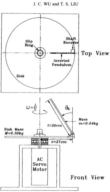
The system of an inverted pendulum hinged to a rotating disk as shown in Fig. 4 is used to represent a circular motion of a motorcycle on which a rider leans to maintain stability. This apparatus is designed in such a way that it can to some extent represent motion control involving the leaning angle of the rider's body (the inverted pen- dulum) and the banking speed of the motorcycle (the disk). The inverted pendulum representing a rider's body in leaning motion is hinged to the rim of the rotating disk. The centrifugal force resulting from the rotating motion of the disk enables the inverted pendulum to rotate relative to the tangential direction of the disk. Rotating speeds of the disk that correspond to riding speeds of the motorcycle dominate the leaning motion of the inverted pendulum that corresponds to the rider's leaning motion. This study controls the tilting inverted pendulum to approach target angles using fuzzy control with both GA and an auto-tuning method. It is desired to vary rotating speeds, so that the tilt angle can be regulated by the centrifugal force that arises from disk rotation.
ft 446 J.C. WU and T. S. LIU
Top View
Disk Mass M=6.3Okg t M a s s m=O.O4k 9F r o n t V i e w
I _ _ ]Fig. 4. Schematic diagram of inverted pendulum hinged to rotating disk.
The Lagrangian formulation is a systematic procedure that results in a set of second-order ordinary differential equations to represent the dynamics of the system. By contrast, the Hamiltonian formulation constructs the system in terms of general- ized coordinates and generalized m o m e n t a and results in a set of first-order equations of motion. F u r t h e r m o r e , solution trajectories for equations of motion derived by the Hamiltonian formulation form a phase space. This facilitates visualization of the qualitative behavior of the system. For the present study, the Lagrangian L that is the difference of the kinetic energy and the potential energy is formulated as
1 "2 ~ .2 _ Xmg l . c o s O b ,
L = 5IMO + ~IbO b (3)
Fuzzy control of rider-motorcycle system 447
1 2
I b = ~ml
1 2 - - s i n O h ) 2 •
I ~ = ~ M r + m ( r 1 El.
To derive Hamilton's equations, generalized coordinates and generalized momenta are defined as
[~b I
= r P ° b ~ (4)q = P LPo_J"
By the Hamiltonian formulation [20], Hamilton's equations are written as 1
Ob = --~b P Ob
O = 1 PO
IM (5)
I c 2 Cob Pob = mgl'sinOb -- 7 . 2 P o -- ---~b pob
2IM
C ~
Po = u - --Z-~po, Ia,
where u denotes the generalized force, i.e. the torque of the motor, Cos and Co are respectively damping coefficients of the inverted pendulum and the disk to account for viscous damping at joints, and the moment of inertia is formulated as
Ic = ml(r - ½1. sin 0b) COS 0 b. (6)
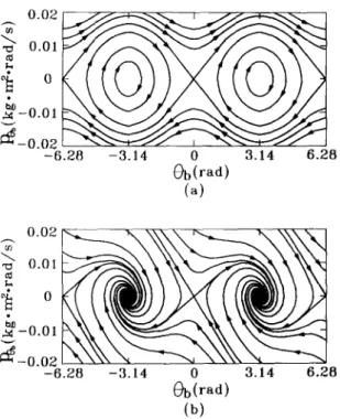
Neglecting generalized force and friction, i.e. u = 0 and Cob--Co = 0, Eqn (6) gives equilibrium points: p = 0, Ob = 0, _+rr, +_2rr .. . . . and 0 is arbitrary. Figure 5a shows the phase plane of Ob and Pob for examining stability. The phase portrait is periodic with a period of 2rr. A saddle point is present at equilibrium position (0, 0) whereas centers are at equilibrium positions Or, 0) and (-rr, 0). By contrast, if
Cob 4= 0 in Eqn (6), stable nodes are present at equilibrium positions (rr, 0) and (-~r,
0) as depicted in Fig. 5b. Except for trajectories that terminate at the unstable equilibrium position (0, 0), all trajectories converge to the stable equilibrium positions (rr, 0) and (-rr, 0). These stable equilibrium positions represent the vertically down- ward position of the pendulum. Nevertheless, the unstable equilibrium position (0, 0) cannot be maintained since the trajectory diverges away from that position.
5. SIMULATION RESULTS
In this study, initial conditions are prescribed as: the angle of inverted pendulum
Ob = 36 °, the angular velocity of inverted pendulum 0b = 0, and the angular velocity
of motor to = 0. The inverted pendulum is initially supported by a vertical strut such that 0 b cannot be larger than 36 °. Four cases for target angles of 25, 20, 15, and 10 ° of the inverted pendulum are investigated. Fuzzy coarse-tuning control is designed to facilitate the angle of the inverted pendulum approaching the neighborhood of target angles. The fuzzy fine-tuning control is in turn carried out to achieve desired dynamic performance, i.e. smaller overshoot and oscillation. Since P (positive) and N
448 J.C. WU and T. S. LIU
002
4
,..~-0.01 ~ - 0 02 -6.28 -3.14 0 3.14 6.28 Ob(rad) (~) 0.02 - -6.28 -3.14 0 3.14 6.28 ~b(rad) (b)Fig. 5. Phase planes of Ob and po~, (a) without friction and (b) with friction.
(negative) are fuzzy subsets for input variables as depicted in Fig. 3, four fuzzy identification rules are defined for fuzzy control:
IF e(k) is P A N D ec(k) is P T H E N co = p~. e(k) + P l ' e c ( k ) + p~
IF e(k) is P A N D ec(k) is N T H E N (0 = p~. e(k) + p~. ec(k) + p~
IF e(k) is N A N D ec(k) is P T H E N (0 = p3. e(k) + p~.ec(k) + p~
IF e(k) is N A N D ec(k) is N T H E N w = p~.e(k) + p~. ec(k) + p~
where error e(k) denotes the current angle of the inverted pendulum minus the target angle and error change ec(k) the current error minus the error of the previous sampling time. In the above four rules, 12 parameters p} in the consequence are determined by G A . Similarly, the auto-tuning m e t h o d contains four rules of the form
IF ec(k) is P A N D ecc(k) is P T H E N Ko = p~" ec(k) + p~. ecc(k) + p~
IF ec(k) is P A N D ecc(k) is N T H E N Ko = p~" ec(k) + p~. ecc(k) + p~
IF ec(k) is N A N D ecc(k) is P T H E N K o = p~'ec(k) + p~. ecc(k) + p72
IF ec(k) is N A N D ecc(k) is N T H E N K 0 = p~. ec(k) + p~. ecc(k) + p8
where the change of error change ecc(k) denotes the current error change minus the
i
error change of the previous sampling time. Although the parameters PS, i = 1 to 8 and j = 0, 1, 2, are crucial for both fuzzy control and the auto-tuning method, it is very difficult to determine the parameters. In view of the promising searching capability of G A , the optimal set of the 24 parameters is determined by G A .
Fuzzy control of rider-motorcycle system 449 Each parameter in the parameter set is coded as an eight-bit string. The mapping of the parameter set onto the eight-bit string determines the desired range of resolution for the parameter set. The mapping is written as
i binrep
pj = - 2 . 5 + - - , (7)
51
where binrep is an integer value represented by the eight-bit string. In this eight-bit representation, maximum and minimum integer values represented by eight-bit strings correspond to parameter values of 2.5 and - 2 . 5 , respectively. The resolution is calculated as 0.0196. Since there are 24 parameters in the parameter set, the strings are concatenated to form a 192-bit string representing one unit of the population. One unit represents one possible solution among 2192 solutions. In this study, the population size is 40 and the mutation rate is 0.001. The fitness function for the GA implementation is executed only in the fine-tuning period, i.e. in the neighborhood of target angles. The fitness function can be defined as
kf
F = ~ [e2(k) + ec2(k)]. (8)
k = k o
The average values of fitness functions for population size np of a generation are calculated according to
np kf
A F = 1 ~ ~ [e:(k) + ec2(k)]. (9)
n p i=1 k = k o
Thereby the variation of fitness functions between any two generations can be observed. The initial generation is chosen at random. An optimal solution can be found using operators in the GA, by which the fitness function can reach the minimum in numerous generations.
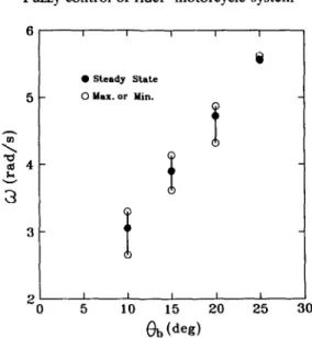
Figure 6 shows the evolution of the average and best fitness functions over 200 generations for four target angles. Since the crossover operator is implemented to provide new points for further testing, there are several local peaks in Fig. 6a. Nevertheless, values of fitness functions decrease in trend and converge. Figure 7 shows simulation results of Ob and 09 for four target angles. From Fig. 7b, it can be seen that the steady state values of to increase with target angles. The variation for angular velocity to of the motor with four target angles is depicted in Fig. 8. The solid circle denotes the steady state value of to. Moreover, the upper and lower circles indicate the maximum and minimum values of to through the period of fine-tuning control, respectively. The variation of to for target angle 25 ° is the smallest. For a circular motion of a rider-motorcycle system, a rider banks at an angle in order to maintain an adequate balance between the gravitational and centrifugal forces. Both the banking movement of the rider's body and the riding speed play important roles in stabilizing circular motion. Stability can be achieved by an appropriate relation between riding speeds and leaning angles of the rider. Riding speeds corresponding to the values of to increase with required leaning angles of the rider's body that correspond to the values of 0 b in the experimental apparatus. Comparison of four cases of inverted pendulum motion shows that a larger leaning angle of the rider
450 J . C . W U a n d T . S. L I U 40 O *g 3o 20 Q9 0 k I r _ _ _ 2 5 ° . . . 2 0 ° " \ ', i ,o k _ " ~ > ~ 7 r ' " ~ : ~ , " " " ... , 0 50 I 0 0 150 2 0 0 N u m b e r o f g e n e r a t i o n s ( a ) 1 0 1 i ~ O \ . . . :~ 10 ° ~ . ~ - - - - - 2 5 ° ~ ": . . . 2 0 ° l f f I ~ i - - ~ 1 5 ° - - 1 0 o \ ".. \ . . 1 6 2 I " - . - ... 10 -:3 _ _ I I t 0 5 0 100 150 N u m b e r o f g e n e r a t i o n s (b) 2 0 0
Fig. 6. (a) Average and (b) best fitness function evolution for different target angles.
4 0 - - i i 20 10 1 - - I 0 0 2 4
i
2 5 * 2o °/
I I 6 8 10 T i m e (s) (a) 10.0 7 . 5 5 . 0 2 5 ° i 5 ° lo o'/
2 . 5 ~ - - F i I 0"00 2 4 6 8 T i m e (s) ( b ) 10Fig. 7. Variations of (a) angle of inverted p e n d u l u m and (b) angular velocity of m o t o r for different target angles.
Fuzzy control of rider-motorcycle system 451 4 v 3 I I I I O Steady S t a t e 0 M a x . o r M i n .
I
l 2 I I I I I 0 5 10 15 20 25 30 ~b(deg)Fig. 8. Variation of angular velocity of motor with different target angles.
requires a faster riding speed for stabilization and results in smaller variation of the riding speed. In addition, larger leaning angle exhibits a better stability of the system.
6. EXPERIMENTAL SETUP AND RESULTS
The schematic diagram and photograph of the experimental setup are shown in Figs 9 and 10, respectively. A shaft encoder at the root of the inverted pendulum is used to measure the tilt angle. An interface card transmits the position count to the PC for fuzzy control. The sampling time of PC command is 1 ms. A motor driver receives control signals via the interface card, and enables instantaneous rotation motion of the A.C. servo motor. The initial angle of pendulum
Ob
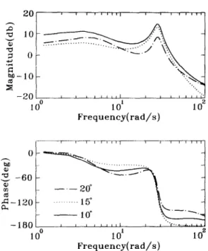
is 36 ° and the rotational velocity of the motor 09 = 0.Figure 11 depicts experimental results for variations of 0 b at three different target angles. Data are collected at a sample rate of 50 Hz. Curve wiggle is present in Fig. 11 due to backlash in the gear box and limited resolution of the encoder. The collision generated from the backlash of the gear box occurs whenever the motor undergoes large acceleration and deceleration. The collision can hence be treated as random disturbances. Moreover, as variations of (0 decrease, the degrees of collision decrease. The proposed method can work well as shown in Fig. 11 despite random disturbance. Figure 12 depicts power spectra that account for control effort arising from motor output. Since the power amplitude of w increases with target angles as shown in Fig. 12, the collision increases with target angles. The angular oscillation of the inverted pendulum as shown in Fig. l l c is hence smaller than those in Fig. l l a and b. Figure 13 shows Bode plots of 0b versus motor angular velocity ¢9 at different target angles. Gain margins of all three cases are very large. Phase margins of target angles 10, 15 and 20 ° are 19, 10 and 42 °, respectively. The smaller target angle results in larger gain and phase lag. Compensating for larger phase lag requires more control effort. Corresponding to a circular motion of a rider-motorcycle system, a rider must
452 J . C . WU and T. S. L I U Servo Motor Driver Binary Counter Interface Card 80486 PC ]~ Interface Card
Fig. 9. Block diagram of experimental setup.
Fuzzy control of rider-motorcycle system 453 4O ~ - 3 0 • ~ 2 0 0 0 4 0 --- 30 2 0 0 0 2 4 6 8 10 T i m e ( s ) (a) 2 4 6 8 10 T i m e ( s ) (b) 4 0 , - - 3 0 0) "~ 2 0 0 2 4 6 8 10 T i m e ( s ) (c)
Fig. 11. Experimental results for angle variations of inverted pendulum at target angles (a) 20 °, (b) 15 ° and (c) 10 °. 104 i i i i ~ 102 :'x
L/
' ~ " /
°:~'~ ~o° ---eo
° ~ ,,. ,:'~..:~
10-2 ... 15" " "" t I I I 0 2 4 6 8 10 F r e q u e n c y (Itz)Fig. 12. Power spectra of angular velocity of motor for different target angles.
bank at a large enough angle in order to maintain balance when the radius of the circular motion is constant. As the target angle decreases, the sensitivity of 0b versus to, i.e. gain in Fig. 13, increases. Accordingly, a smaller leaning angle exhibits a poor stability control for the circular motion of a rider-motorcycle system.
454 J.C. WU and T. S. LIU ' ~ 0 , i i ~ i i l l I J i , i J i ~ J "~ 1 0 - "~ N ._~.. :...-:=.: ..'2"7...:..-Z'.. . ~, - 2 0 L ~ , , , ,~,J J ~ t , ~ ,,i" 1 0 ° 1 0 t 1 0 e F r e q u e n c y ( r a d / s ) 2 - 6 0 f ~ a~ ~ - 1 2 0 - - ,,,,~ ""'r.., ... •, / U F ~ - - J[ U ~ J I I l I J I 1 0 ° 101 102 F r e q u e n e y ( r a d / s )
Fig. 13. Bode plots of transfer functions in experiment for different target angles.
7. CONCLUSIONS
This study develops fuzzy control integrated with both G A and an auto-tuning m e t h o d for stability control of a r i d e r - m o t o r c y c l e system. The proposed experiment provides a useful means to understanding stability of a r i d e r - m o t o r c y c l e system during circular motion. In contrast to previous works in which the auto-tuning m e t h o d is used to adjust PID gains, the current study employs the auto-tuning m e t h o d to on-line tune output gains of fuzzy control. Unlike previous works in which member- ship functions are determined by a G A , in this paper the optimal 24 parameters of both control rules and tuning rules are obtained by a G A . Simulation results show that a larger leaning angle of the rider exhibits a better stability control. The steady state angular velocity of the m o t o r increases with target angles. Experimental results depict curve wiggle of pendulum angles in the time domain due to backlash in the gear box and limited resolution of the encoder. Bode plots obtained from experi- mental data are given to illustrate the degree of influence of rider's leaning angle during circular motion. The smaller the desired leaning angle, the more difficult it is to maintain stability. The results are consistent with a human's riding experience.
Acknowledgement--The authors would like to acknowledge the support of the National Science Council, Taiwan, R.O.C. under grant number NSC84-2212-E009-004.
R E F E R E N C E S
1. Katayama T., Aoki A. and Nishimi T., Control behaviour of motorcycle riders. Vehicle Syst. Dynam.
Fuzzy control of rider-motorcycle system 455
2. Liu T. S. and Wu J. C., A model for a rider-motorcycle system using fuzzy control. IEEE Trans. Syst.
Man Cybern. 23, 267-276 (1993).
3. Zadeh L. A., Fuzzy sets. Inf. Control 8, 338-353 (1965).
4. Zadeh L. A., Making computers think like people. IEEE Spectrum 21, 26-32 (1984).
5. Mamdani E. H., Application of fuzzy algorithms for control of a simple dynamic plant. Proc. Inst.
Elect. Engrs 121, 1585-1588 (1974).
6. Yamakawa T., Stabilization of an inverted pendulum by a high-speed fuzzy logic controller hardware system. Fuzzy Sets Syst. 32, 161-180 (1989).
7. Procyk T. J. and Mamdani E. H., A linguistic self-organizing process controller. Automatica 15, 15-30 (1979).
8. Ollero A. and Garcia-Cerezo A. J., Direct digital control, auto-tuning and supervision using fuzzy logic. Fuzzy Sets Syst. 30, 135-153 (1989).
9. Harris C. J. and Moore C. G., Phase plane analysis tools for a class of fuzzy control systems. IEEE
Int. Conf. on Fuzzy Systems, pp. 511-518, San Diego, CA (1992).
10. Kosko B., Neural Networks and Fuzzy Systems. Prentice-Hall, Englewood Cliffs, NJ (1992).
11. Lee T. H., Hang C. C., Lian L. L. and Lim B. C., An approach to inverse nonlinear control using neural networks. Mechatronics 2,595-611 (1992).
12. Ozaki T., Suzuki T., Furuhashi T., Okuma S. and Uchikawa Y., Trajectory control of robotic manipulators using neural networks. IEEE Trans. Ind. Elect. 38, 195-202 (1991),
13. Hong H. P., Park S. J., Han S. J., Cho K. Y., Lira Y. C., Park J. K. and Kim T. G., A design of auto-tuning PID controller using fuzzy logic. Proc. of Int. Conf. on Industrial, Electr. Control,
Instrumentation, and Automation, pp. 971-976, San Diego, CA (1992).
14. Karr C., Applying genetics to fuzzy logic. AI Expert 6(3), 38-43 (1991).
15. Kickert W. J. M. and Mamdani E. H., Analysis of a fuzzy logic controller. Int. J. Fuzzy Sets Syst. 1, 29-44 (1987).
16. Takagi T. and Sugeno M., Fuzzy identification of systems and its applications to modeling and contorl.
IEEE Trans. Syst. Man Cybern. SMC-15,116-132 (1985).
17. Holland J., Adaptation in Natural and Artificial Systems. University of Michigan Press, Ann Arbor, MI (1975).
18. Goldberg D. E., Genetic Algorithm in Search, Optimization, and Machine. Addison-Wesley, Reading, MA (1989).
19. Krishnakumar K. and Goldberg D. E., Control system optimization using genetic algorithms. J.
Guidance, Control Dynam. 15,735-740 (1992).