A new yellow fluorescent dopant for high-efficiency organic
light-emitting devices
Yao-Shan Wu
a, Tswen-Hsin Liu
b, Hsian-Hung Chen
a, Chin H. Chen
c,*
a
Department of Applied Chemistry, National Chiao Tung University, Hsinchu, Taiwan 300, ROC b
Institute of Electro-Optical Engineering, National Chiao Tung University, Hsinchu, Taiwan 300, ROC c
Display Institute, Microelectronics and Information System Research Center, National Chiao Tung University, Hsinchu, Taiwan 300, ROC Received 15 December 2004; received in revised form 13 July 2005; accepted 12 August 2005
Available online 12 September 2005
Abstract
We describe the design and synthesis of a sterically hindered yellow dopant, tetra(t-butyl)rubrene (TBRb) which, when doped in either 1,4-bis[N-(1-naphthyl)-NV-phenylamino]-biphenyl or aluminum tris(8-hydroxyquinoline) (Alq3) as emitter, shows nearly 25% increase in luminance
efficiency over that of the state-of-the-art rubrene (Rb) device without significantly effecting its corresponding color. At 5% doping in Alq3and 20
mA/cm2current drive condition, the electroluminescence efficiency of TBRb reaches 8.5 cd/A and 2.8 lm/W with a yellow color of Commission Internationale de l’Eclairage chromaticity coordinates (CIEx,y) = [0.52, 0.48], which is among the best ever reported for yellow electrofluorescence
in organic light-emitting devices. D 2005 Elsevier B.V. All rights reserved. PACS: 85.60.-q; 42.79.-e
Keywords: Doping; Fluorescence; Rubrene; Organic electroluminescent device
1. Introduction
One of the key developments in the advance of organic light-emitting device (OLED) technology can be attributed to the discovery of the doped emitter system[1]. This is because a single host with optimized transport, photophysical and luminescent properties may be used together with a variety of highly fluorescent guest dopants leading to electrolumines-cence (EL) of desirable hues, high efficiencies as well as enhanced operational device stability[2]. This doping principle has also been extended to the exploitation of highly phospho-rescent materials, which can lead to devices with nearly 100% internal EL efficiency[3].
To date, most of the dopant work have been driven by the need to develop highly efficient, stable and saturate red, [4]
green[5]and blue [6]fluorescent emitters for the burgeoning commercialization activities of low temperature poly silicon active matrix full color displays[7]. Relatively few works[8,9]
appear to have been directed toward the design and synthesis of
yellow dopants. Yet, according to a recent survey in area-color display market, particularly of passive matrix OLEDs, the combination of blue and its complimentary color — yellow is still preferred by most of the customers. In addition, yellow in combination with sky blue emissions is also one of the key components as the construction of white OLEDs which is the basis for mask-free full color fabrication technology recently disclosed by Sato [10]. Therefore, there exists a continuing need and innovative opportunity for the development of highly efficient yellow dopant materials for various OLED display applications.
For benchmark purpose of comparing yellow dopants in OLED, the archetypical 5,6,11,12-tetraphenylnaphthacene (rubrene) [11] is still the one to beat. As a matter of fact, rubrene (Rb) is probably one of the most interesting and extensively studied dopants of them all. Apart from its near unity photoluminescent (PL) quantum efficiency in the yellow region of the visible spectrum, Rb possesses several attractive properties that are unsurpassed, such as its resistance to concentration quenching (up to 7%),[10]its bipolar character
[12,13] and its ability to enhance device stability (e.g. by trapping holes in the electron transport aluminum
tris(8-0040-6090/$ - see front matterD 2005 Elsevier B.V. All rights reserved. doi:10.1016/j.tsf.2005.08.229
* Corresponding author. Tel.: +886 3 5712121x59200; fax: +886 3 5737681. E-mail address: [email protected] (C.H. Chen).
hydroxyquinoline) (Alq3) layer) [14]. Another major
applica-tion of Rb popularized by Hamada et al. at Sanyo [15]is its propensity to ‘‘assist’’ the efficient transfer of energy from host Alq3to
4-(dicyanomethylene)-2-t-butyl-6-(1,1,7,7-tetramethyl-julolidyl-9-enyl)-4H-pyran (DCJTB) [16] from which a near saturated red emission can be achieved without compromising its luminous efficiency. Recently it was reported that rubrene can also be used as a co-host with Alq3from which the red
fluorescent DCJTB doped devices can achieve more saturated red emission and high efficiency with excellent operational stability[17].
In the effort of searching for an ‘‘improved dopant’’ for Rb and to improve the device performance of the Rb doped emitters in OLED, we have discovered and describe herewith the synthesis and fabrication of a new yellow dopant — 2,8- di(t-butyl)-5,11-di[4-(t-butyl)phenyl]-6,12-diphenylnaphtha-cene, trivially named as tetra(t-butyl)rubrene (TBRb) which shows nearly 26% increase in EL efficiency over that of Rb without compromising its color as well as its bipolar character. 2. Experimental section
Rb was purchased commercially. TBRb was synthesized followed by Scheme 1 from 1,1-di[4-(t-butyl)phenyl]-3-phe-nylpropargyl alcohol (1) following a literature procedure [18]
and the latter was prepared from 4,4V-di(t-butyl)benzophenone
[19] and lithium phenylacetylide in tetrahydrofuran (THF) analogous to the preparation of 1,1,3-triphenylpropargyl alco-hol[20]. The molecular structures of TBRb were confirmed by
1
H-nuclear magnetic resonance, mass spectral, elemental analyses. Both dopants were train sublimed prior to their device fabrication and their purities were thoroughly checked by thin layer chromatography as well as high-performance liquid chromatography to be > 99%. UV – Vis and Photoluminescence spectra were measured by Hewlett Packard 8453 and Acton Research Spectra Pro-150, respectively. Thermal properties such as glass transition temperature (Tg), melting point (Tm) and
decomposition temperature (Td) were measured by Seiko SSC
5200 and Seiko TG/DTA 200, respectively.
Device structures applied in this article were shown inFig. 1. In device A, the structure was [indium tin oxide (ITO, 170 nm)|CFx|1,4-bis[N-(1-naphthyl)-NV-phenylamino]biphenyl
(NPB, 90 nm)|v% dopant + Alq3(37.5 nm)|Alq3(37.5 nm)|LiF
(1 nm)|Al (200 nm)], where ITO on glass (0.7 mm thick) with
20 nm SiO2barrier layer was used as the substrate which has a
sheet resistance of ¨10 V/g, CFx as the hole-injection layer,
NPB as the hole transport layer (HTL), v% dopant + Alq3as the
emitter, Alq3as the electron transport layer and LiF/Al as the
electron-injection layer and cathode. In device B, the Rb or TBRb was doped in NPB (20 nm) as a separate emitter where the hole transport layer NPB was thinned to 70 nm while Alq3
electron transport layer was increased to 75 nm to balance the injected carriers in the device.
Prior to the organic deposition, the ITO coated glass plate was patterned by conventional lithography and then thoroughly cleaned by scrubbing, sonication, vapor degreasing, and oxygen plasma treatment. All organic layers were prepared in a vacuum chamber (about 10 3Pa) by vapor deposition using resistively heated tantalum boats. Typically, the deposition rate was 0.4 nm/s and the substrate to evaporant source distance was about 30 cm. The dopant was co-evaporated from resistively heated graphite boat which was controlled by a temperature controller and monitored through a thermocouple inserted into the bottom of the boat. By careful control of the dopant boat temperature, it was possible to precisely co-evaporate a determined amount of dopant dispersed into the host emitter layer as measured in v/v%. After the deposition of the organic layers and without a vacuum break, the ultra thin layer of 1 nm of LiF followed by 200 nm of Al was deposited through a patterned shadow mask on top of the organic layers using separately controlled sources to complete the cathode. The active area of the EL device, defined by the overlap of the ITO and the cathode electrodes, was 0.1 cm2. The EL emission spectra and current – voltage – luminance characteristics of the devices with encapsulation were measured in ambient imme-diately with a diode array rapid scan system using a Photo Research PR650 spectrophotometer and a computer-controlled
O OH (a) (b) 1 TBRb Scheme 1. Synthesis of TBRb. Al-LiF Structure A Alq3 NPB CFx ITO/ glass Doped Alq3 Structure B Alq3 NPB Doped NPB
direct current source. The operational stability of the devices was measured with encapsulation in nitrogen atmosphere to alleviate the influence of encapsulation condition. The lowest unoccupied molecular orbital (LUMO)/highest occupied mo-lecular orbital (HOMO) energy levels were measured using the atmospheric ultraviolet photoelectron analysis system (Riken AC-2) and the photoluminescence spectra were obtained on the Acton Research Spectra Pro-150.
3. Results and discussion 3.1. Photo-physical properties
Solution (1,2-dichloroethane) absorption and photolumines-cence(PL) spectra of both of these dopants are compared in
Fig. 2in which we found absorption spectra of Rb and TBRb are very similar with well defined vibronic bands observed at maximum near 528, 495, 494 nm and so are their PL spectra with kmax of 556 nm for Rb and 567 nm for TBRb. Their
relative quantum efficiencies in dilute solution (absorbance ¨0.05) are similar with TBRb (1.06) only slightly higher than that of Rb (1.0).
3.2. Thermal properties and LUMO/HOMO
By thermogravimetric analysis and differential scanning calorimetry, the weight loss (Td) of TBRb is less than 5% upon
heating to 410-C, which is 22 -C thermally more stable than that of Rb. Neither Rb nor TBRb showed a detectable Tg. But,
Rb does have a melting temperature (Tm= 330-C) while TBRb
exhibits none. This data suggest that TBRb is also more resistant to crystallization than Rb.
By direct photoionization measurements, the LUMO/HO-MO level of TBRb is found to be at around 3.20 / 5.38 eV with a bandgap energy (Eg) of 2.18 eV that is essentially identical to
that of Rb with 3.31 / 5.49 eV (Eg¨2,18 eV).
3.3. EL performance
To evaluate the EL performance of TBRb and also to benchmark against Rb, we doped each of the dopants in Alq3
and NPB as emitters in devices A and B, respectively. The plots of doping concentration (v/v%) in Alq3 vs. luminance
efficiency (cd/A) of TBRb and Rb at 20 mA/cm2are compared inFig. 3. The peak efficiency of both Rb (7.9 cd/A) and TBRb (9.9 cd/A) are found at 2%. But, at these low doping concentrations, not all of the green Alq3 emission could be
quenched by the dopants. In the insert where the Commission Internationale de l’Eclairage chromaticity coordinates (CIEx,y)
coordinates are plotted against doping concentration, it is found that near saturated yellow color is reached only at over 5% doping where Rb has a CIEx,y= [0.52, 0.48] and TBRb has a
similar CIEx,y= [0.52, 0.48]. At 5% doping and a drive current
density of 20 mA/cm2and voltage of 9.5 V, the EL efficiency of TBRb (8.5 cd/A and 2.81 lm/W) is nearly 25% higher than that of Rb (6.8 cd/A and 2.36 lm/W). We believe this EL performance is one of the best ever reported for yellow electrofluorescence in OLEDs. Other device attributes of TBRb and Rb doped (at 5%) emitters are compared inTable 1.
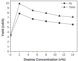
InFig. 4, we show the plots of doping concentration (v/v%) in NPB vs. luminance efficiency (cd/A) of TBRb and Rb at 20 mA/cm2drive condition in device B. Both dopants find their luminance efficiencies plateaued after 2% and become essen-tially independent on the doping concentration. From 2% – 14%, TBRb has an efficiency of around 9.6 cd/A which is near 25% more efficient than that of Rb of 7.7 cd/A. In theTable 1, we found that at 5% doping, Rb has a CIEx,y= [0.48, 0.51] and
TBRb has a similar CIEx,y= [0.47, 0.51] that are quite different
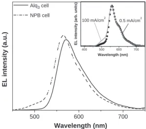
from those of device A. Closer examination of the EL spectra of 5% TBRb doped devices A and B are shown inFig. 5which reveals that the latter has the emission kmaxpeak at 564 nm that
is 8 nm hypso-chromically shifted from that of device A (kmax= 572 nm). From the profile of the EL spectrum of device
B and upon convolution, it is evident that the emission of doped NPB device is composed of TBRb and a small amount of Alq3 emission at kmax ¨520 nm, which is apparently
generated from carriers recombination in the electron transport layer near the interface of the emitter. In the insert, the EL spectra of 5% TBRb doped device B at low (0.5 mA/cm2) and high (100 mA/cm2) current drive conditions are compared. The
400 450 500 550 600 650 700 0.0 0.2 0.4 0.6 0.8 1.0 1.2 Normalized intensity Wavelength (nm) Rb (UV) TTb-Rb (UV) Rb (PL) TTb-Rb (PL)
Fig. 2. Absorption and solution PL spectra of Rb and TBRb.
0 2 4 6 8 10 12 14 0 1 2 3 4 5 6 7 8 9 10 Yield (cd/A) Doping Concentration (v%) Rb TBRb
Fig. 3. Luminance efficiency vs. concentration of Rb and TBRb doped Alq3 emitter (device A).
amount of Alq3 emission near 520 nm increases with high
current density can be rationalized by the increasing amount hole leakage into the Alq3 layer for recombination. This
phenomenon is particularly acute due to the insufficient hole trapping by the dopant at high current drive condition. Finally, it was noted that the drive voltage of TBRb doped device B at 7.9 V is about 20% lower than that of device A which is 9.5 V. This gain in power saving which is independent of doping concentration can be explained by the efficient electron trap of TBRb in NPB, which results from its low lying LUMO (3.2 eV) in relation to the electron transport Alq3of 3.0 eV.
3.4. Test of device operational stability
Fig. 6 exhibits the operational stability of device using device structure A and 5% doping device in the same initial luminance (L0= 1000 cd/m2). Lifetime (t1 / 2) of the device
using Rb as dopant is near 1500 h. However, device using TBRb shows slightly longer operational stability of 1700 h. It is because EL efficiency of TBRb doped device is higher than that of Rb, so TBRb doped device can get the same luminance under less current density.
4. Conclusion
We have discovered a new yellow dopant — tetra (tQbutyl)rubrene (TBRb) which is based on the design strategy of steric substitution of the rubrene core structure. When doped in either NPB or Alq3as emitter, TBRb shows a 25% increase
in luminance efficiency over that of Rb doped device without significantly effecting its color. At 5% doping in Alq3and 20
mA/cm2 drive current density at 9.5 V, the EL efficiency of TBRb doped device A reaches 8.5 cd/A, and 2.8 lm/W with a yellow color coordinates of CIEx,y= [0.52, 0.48]. Similarly
doped in NPB also yielded the same high efficiency except the power efficiency is increased to 3.8 lm/W with a slightly hypso-shifted color of CIEx,y= [0.47, 0.51]. The enhancement
in luminous efficiency is believed to come from the balance of injected carriers near the recombination site which results in nearly 1.6 V drop in drive voltage in device B. However, the EL spectra of both TBRb and Rb doped NPB emitters are contaminated with a small but significant amount of Alq3
emission which is believed to have arisen from the leakage of holes into the adjacent electron transport layer. This competing
Table 1
EL performance of 5% Rb and TBRb doped Alq3(A) and NPB (B) emitters driven at 20 mA/cm2
Dopant Voltage (V) Luminance (cd/m2) Lum. yield (cd/A) Efficiency (lm/W)
CIEx,y EL peak (nm) FWHM (nm) Device A Rb 9.0 1350 6.75 2.36 0.52, 0.48 568 72 TBRb 9.50 1700 8.50 2.81 0.52, 0.48 572 72 Device B Rb 7.58 1544 7.72 3.20 0.48, 0.51 564 72 TBRb 7.93 1913 9.56 3.79 0.47, 0.51 568 72 0 2 4 6 8 10 12 14 16 0 2 4 6 8 10 12 Yield (cd/A) Doping Concentration (v%) Rb TBRb
Fig. 4. Luminance efficiency vs. concentration of Rb and TBRb doped NPB emitter (device B).
500 600 700
400 500 600 700
100 mA/cm2
EL intensity (arb. units)
Wavelength (nm) 0.5 mA/cm2 EL intensity (a.u.) Wavelength (nm) Alq3 cell NPB cell
Fig. 5. EL spectra of 5% TBRb doped NPB and Alq3emitters (insert shows EL spectra of doped NPB emitter driven at 0.5 and 100 mA/cm2).
0 500 1000 1500 2000 2500 0 200 400 600 800 1000 Luminance (cd/m 2 ) Time (hr) Rb TBRb
Fig. 6. Operational lifetime of the device doped with Rb and TBRb using device structure A.
exciton generation in Alq3layer is particularly severe at high
current drive conditions. As a result, although device B has certain advantage over A in its resistance to concentration quenching at high doping concentration, the tendency of color shifting during pulse drive at high current conditions would make NPB doped device B undesirable for passive matrix display applications.
Acknowledgment
This work was supported by the MOE Program for Promoting Academic Excellent of Universities under the grant number 91-E-FA04-2-4-B and the National Science Council of Taiwan, Republic of China. A research grant of Industry/ Academia Cooperation Project provided by e-Ray Optoelec-tronics Technology Co., Ltd. is gratefully acknowledged. References
[1] C.W. Tang, S.A. VanSlyke, C.H. Chen, J. Appl. Phys. 65 (1989) 3610. [2] For review, see: C. H. Chen, J. Shi, C. W. Tang, Macromol. Symp. 125
(1997) 1.
[3] M.A. Baldo, M.E. Thompson, S.R. Forrest, Nature 403 (2000) 750. [4] T.K. Hatwar, G. Rajeswaran, J. Shi, Y. Hamada, H. Kanno, H. Takahashi, Proc. 10th International Workshop on Inorganic and Organic Electrolu-minescence (EL’00), Hamamatsu, Japan, 2000 (December 4 – 7), p. 31.
[5] C.H. Chen, C.W. Tang, Appl. Phys. Lett. 79 (2001) 3711. [6] J. Shi, C.W. Tang, Appl. Phys. Lett. 80 (2002) 3201.
[7] G. Rajeswaran, M. Itoh, M. Boroson, S. Barry, T.K. Hatwar, K.B. Kahen, K. Yoneda, R. Yokoyama, T. Yamada, N. Komiya, H. Kanno, H. Takahashi, Proceedings of the Society for Information Display, California, U.S.A, 2000 (May 14 – 19), p. 1.
[8] X.Q. Lin, B.J. Chen, X.H. Zhang, C.S. Lee, H.L. Kwong, S.T. Lee, Chem. Mater. 13 (2001) 456.
[9] B.W. D’Andrade, M.A. Baldo, C. Adachi, J. Brooks, M.E. Thompson, S.R. Forrest, Appl. Phys. Lett. 79 (2001) 1045.
[10] Y. Sato, T. Ogata, S. Ichinosawa, Y. Murata, Synth. Met. 91 (1997) 103. [11] Y. Sato, Semicond. Semimet. 64 (2000) 209.
[12] Y. Hamada, T. Sano, K. Shibata, K. Kuroki, Jpn. J. Appl. Phys. 34 (1995) L824.
[13] Z. Zhang, X. Jiang, S. Xu, T. Nagatomo, O. Omoto, J. Phys., D 31 (1998) 32.
[14] H. Aziz, Z.D. Popovic, Appl. Phys. Lett. 80 (2002) 2180.
[15] Y. Hamada, H. Kanno, H. Fujii, T. Tsujioka, H. Takahashi, ACS Poly Millennial Abstract, Hawaii, U.S.A, 2000 (December 9 – 13), p. 167. [16] C.H. Chen, C.W. Tang, J. Shi, K.P. Klubek, Macromol. Symp. 125 (1997)
49.
[17] T.H. Liu, C.Y. Iou, C.H. Chen, Appl. Phys. Lett. 83 (2003) 5241. [18] P. Essenfeld, Eur. Patent No. 302195, 1998.
[19] H.W. Gibson, S.-H. Lee, P.T. Engen, P. Lecavalier, J. Sze, Y.X. Shen, M. Bheda, J. Org. Chem. 58 (1993) 3748.