國 立 交 通 大 學
資訊科學與工程研究所
碩 士 論 文
在即時編譯器中針對混合固定長度指令集所設計的
暫存器分配演算法以求縮減程式碼
Register Allocation of JIT Compiler for Mixed-Width ISA
for Code Size Reduction
研 究 生:楊天元
指導教授:單智君 博士
在即時編譯器中針對混合固定長度指令集所設計的暫存器
分配演算法以求縮減程式碼
Register Allocation of JIT Compiler for Mixed-Width ISA
for Code Size Reduction
研 究 生:楊天元 Student:Tian-Yuan Yang 指導教授:單智君 Advisor:Dr. Jyh-Jiun Shann
國立交通大學 資訊科學與工程研究所
碩士論文
A Thesis
Submitted to Institute of Computer Science and Engineering College of Computer Science
National Chiao Tung University In partial Fulfillment of the Requirements
for the Degree of Master
in
Computer Science and Engineering December 2009
Hsinchu, Taiwan, Republic of China
在即時編譯器中針對混合固定長度指令集所設計的暫存器
分配演算法以求縮減程式碼
研究生:楊天元 指導教授:單智君摘要
在嵌入式系統中儲存程式的記憶體是相當重要的資源,於是減少程式碼的大小成 為了重要的議題。其中一種解決方法是用“混合寬度指令集架構"。一般而言, 這樣的架構提供了兩種固定長度指令集,能夠執行一般指令(通常為 32 位元)以 及短指令(通常為 16 位元)。在這樣的架構中程式可由兩種指令組合而成,如果 程式使用了越多的短指令其程式碼大小就越小。然而短指令上有著一些限制,例 如只能使用較短立即值範圍以及存取較少的暫存器,這些都影響了程式中短指令 使用的比例多寡,其中如何分配可被短指令存取的暫存器影響最大。這篇論文中 我們針對混合寬度指令集架構提出了一個適用於即時編譯器的快速暫存器演算 法,這個演算法能得到26%程式碼縮減。Register Allocation of JIT Compiler for Mixed-Width ISA
for Code Size Reduction
Student: Tian-Yuan Yang advisor:Dr. Jyh-Jiun Shann Institute of Computer Science and Engineering
National Chiao Tung University
Abstract
In embedded system, memory is a precious resource, and that reducing program code size becomes an important issue. One promising approach for code reduction is employing “mixed-width instruction set architecture (ISA)”. This kind of architecture usually provides two fixed width instruction sets, a long instruction set (usually 32-bit) and a short instruction set (usually 16-bit). In other words, program can be compiled into native code by using these two kinds of instructions mixedly. Obviously, the more short instructions are used in the program, the smaller program will be. However, there are some limitations for using short instructions. For example, they can only encode smaller range of immediate value and a subset of whole architecture registers. The short of registers is the most important issue among all limitations. Consequently, a register allocation which can allocate register more appropriately is needed for mixed-width ISA. In this thesis we propose a fast specific register allocation algorithm for JIT compiler which is more suitable for mixed-width instruction set architecture than traditional ones and get about 26% code size reduction with neglectable performance loss.
致謝及序言
首先感謝我的指導老師 單智君教授,在我碩士生涯中對我細心教誨,不時的討 論並指點我正確的方向,使我在這些年中獲益匪淺。老師對學問的嚴謹更是我輩 學習的典範。同時,也感謝口試委員,楊武教授與雍忠教授,由於教授們的指導 與建議,才使得此篇論文更加完整與充實。另外,也感謝實驗室的另一位老師, 鍾崇斌教授,在每次的報告之中給予學生指導與建議。 感謝奕緯學長、裕生學長給予我的幫助,不僅僅是研究相關的建議與花費心力的 討論,在平日生活相處上也給予我許多寶貴的經驗,讓我在完成學業之餘也豐富 了我的人生。同時也謝謝實驗室的學長姐、同儕以及學弟妹,在我的碩士生涯中 給予我許多幫助,與你們一同留下的回憶此生難以忘懷。 最後要謝謝我的家人與親友,你們的支持與陪伴,一直是我精神上最堅強的 支柱。 楊天元 2009.12.01Table of Contents
Abstract ... ii Table of Contents ... iv List of Figures ... v Chapter 1 Introduction ... 1 1.1 Research motivation ... 4 1.2 Research objective ... 51.3 Organization of this thesis ... 6
Chapter 2 Background ... 7
2.1 Mixed-width ISA ... 7
2.1.1 Limitations of S-Format instructions ... 8
2.1.2 Mechanisms of mode switch ... 10
2.1.3 Alignment issue of instruction fetch ... 13
2.2 Register allocation algorithms ... 15
2.2.1 Live intervals ... 16
2.2.2 Algorithm of LSRA ... 18
2.3 Summary of background ... 19
Chapter 3 Hierarchical linear scan register allocation ... 20
3.1 Compiler Back-end for Mixed-width ISA ... 20
3.2 Design of HLSRA ... 23
3.2.1 Instruction types ... 23
3.2.2 Register sets ... 24
3.2.3 Register active lists of HLSRA ... 24
3.2.4 Priorities of HLSRA ... 25 3.2.5 Spilling of HLSRA ... 27 3.2.6 Algorithm ... 28 Chapter 4 Experiment ... 32 4.1 Environment ... 32 4.2 Parameter Determination ... 33 4.3 Evaluation Results ... 34
Chapter 5 Conclusions and Future Work ... 37
5.1 Conclusion ... 37
List of Figures
Figure 1-1: Java virtual machine (JVM) ... 3
Figure 1-2: Distribution of limitations of S-Format instructions ... 4
Figure 2-1: L- and S-Format instructions ... 8
Figure 2-2: Example of a program which consists of L- and S-Format ... 12
Figure 2-3: An example for mode switching by instruction encoding ... 12
Figure 2-4: Example of misaligned problem in mixed-width ISAs ... 14
Figure 2-5: Start, end and use point at an interval ... 17
Figure 2-6: Flow chart of linear scan register allocation ... 18
Figure 3-1: Different frameworks of Compiler back-end ... 22
Figure 3-2: L- and S-Format of arithmetic INS ... 22
Figure 3-3: RegisteSetS and RegisterSetL ... 24
Figure 3-4Figure 3-4: An example for priorities of intervals ... 27
Figure 3-5Figure 3-5: An example of HLSRA ... 28
Figure 3-6Figure 3-6: Hierarchical Linear Scan Register Allocation ... 29
Figure 3-7Figure 3-7: Algorithm of HLSRA ... 31
Figure 4-1Figure 4-1: S-Format translation rate ... 33
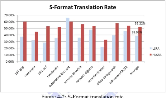
Figure 4-2: S-Format translation rate ... 34
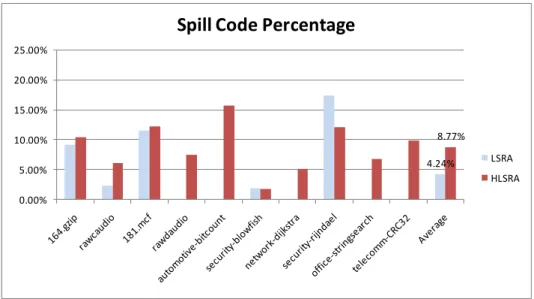
Figure 4-3: Spill code percentage ... 35
Figure 4-4: Code size reduction ... 35
Chapter 1 Introduction
In recent years, RISC processors are increasingly being used to design embedded systems. Using such architecture in embedded system provides certain advantages, such as increased design flexibility, high computing power and low on-chip power consumption. However, RISC processor systems suffer from the problem of poor code density which may require more ROM for storing program code [1].
One promising approach for reducing code size is to employ “Mixed-width instruction set architecture (ISA)” where the processors support different fixed-width instruction sets [2]. In general, there are 32- and 16- bit width instruction sets in Mixed-width ISAs, called L-Format (32bits) and S-Format (16bits) instruction sets. In these ISAs, most L-Format instructions have equivalent S-Format instructions, which means that the same operation could be achieved by either L- or S-Format instruction. Therefore, the more S-Format instructions are used in program the smaller program will be. However, there are several limitations of S-Format instructions such as limited operations, fewer bits to index registers and hold immediate values. Due to these limitations, using S-Format instructions should be under estimation and consideration. Moreover, when processor switches execution mode between L-Format and S-Format, there must be a mechanism to specify the execution mode, called “mode switch”. There are two type of switching mechanisms: “By mode switching instruction” and “By instruction encoding”. In present, mixed-width ISA with mode-switch by instruction encoding is a trend so that our research targets this kind of architecture. More description of mixed-width ISA will be introduced in Chapter 2.
In consideration of variant platforms in embedded systems, portability is an important issue for embedded application development. High portability can decrease development cost. In this case, JAVA is a suitable programming language [3]. In JAVA platform, JAVA compiler is different from traditional compiler, such as C- compiler; it translates JAVA codes into bytecodes, an intermediate representation, rather than native codes. These bytecodes will be executed by execution engines of JAVA virtual machine (JVM) [4] which runs above underlying physical machine as shown in Figure 1-1.
There are two kinds of execution engines in JVM: interpreter which interprets and executes one bytecode at once; Just-In-Time compiler (JIT compiler) which translates a segment of bytecodes into native codes and then executes them. Interpreter has short interactive time but lower performance. In contrast, JIT compiler has better performance but need more startup time than interpreter. JIT compiler is a dynamic compiler for runtime environment, which is used during execution. Therefore, light weight and efficient optimizations (such as a fast register allocation) are important for JIT compiler to reduce compilation overhead.
Figure 1-1: Java virtual machine (JVM)
Using RISC processor to design embedded system is a trend, but as what we mentioned before, it suffers from the problem of poor code density. Although there is an approach such as mixed-width ISA to ease this problem, it still needs some specific compiler optimizations to improve code density for mixed-width ISA. Moreover, these specific optimizations should be fast for JIT compiler because JIT compiler is important execution engine for improving application performance in JAVA and JAVA is a popular and appropriate programming language for embedded application development.
1.1 Research Motivation
So far we have introduced the mixed-width ISA: an approach to reduce code size by supporting L- and S-Format instruction sets. By observing the code produced by traditional compiler, we have discovered that even employing mixed-width ISA with mode switch by instruction encoding, most instructions cannot be formed in S-Format because of the limitations such as insufficient bits for indexing registers and holding immediate value, which means code size is not decreased much. As shown in Figure 1-2, there are only about 38 percents of instructions can be translated into S-Format and about 55 percents of instructions can’t because their operands’ register numbers are out of the range of the registers that can be indexed by S-Format instructions.
Therefore, if we can implement a particular register allocation for mixed-width ISA with mode-switch by instruction encoding, the code size reduction may be improved. Because we want to apply this design to JIT compiler to improve code density, the time complexity of the algorithm must be as low as possible.
Figure 1-2: Distribution of limitations of S-Format instructions
38.93% 0% 10% 20% 30% 40% 50% 60% 70% 80% 90% 100%
S‐Format limitation distribution
Limit of Imm/OP Limit of Operand Register S‐Format Instr.1.2 Research Objective
To make more instructions to fit the limitation of operand registers, we propose a fast register allocation algorithm which takes consideration of S-Format limitations to improve code density. Here we name our design “Hierarchical Linear Scan Register Allocation” (HLSRA), since it allocates register hierarchically through one linear scanning. Along with that we want to apply HLSRA into the JIT compiler, there are two main goals to accomplish:
(1) Reducing code size
HLSRA will allocate registers according to a specific policy which is designed with consideration of register limitation of S-Format instruction. Therefore, the usage of registers will be more appropriate for mixed-with ISA and there will be more instructions meeting register limitation. Therefore, more instructions can be translate into S-Format instructions and code size reduction will be increased
(2) Low time complexity
In dynamic compiler, such as JIT compiler, compilation time makes a great impact on performance. Hence, our design has to be fast and efficient for such run-time environments. To make our design fast, we will implement it based on a known fast register allocation algorithm.
1.3 Organization of this Thesis
The remaining chapters of this thesis are organized as follows: In Chapter 2, we will provide background knowledge about mixed-width ISA and the register allocation algorithm which related to our research. In Chapter 3, we will introduce the basis of our design, and then describe the algorithm of “Hierarchical Linear Scan Register Allocation”. Chapter 4 will demonstrate the simulation environment and results of this work. And finally, Chapter 5, a summary and future work will be made and discussed.
Chapter 2 Background
In the first part of this chapter, we will describe more detail about the mixed-width ISA, including limitations of S-Format instruction, mechanism of mode switch and instruction alignment. In the second part, a fast traditional register allocation algorithm called “linear scan register allocation” will be introduced. At last, we will give a summary of this chapter.
2.1 Mixed-width ISA
Code size is an important issue in embedded system all the time, especially in RISC embedded processor which has suffered from the problem of poor code density. Consequently, mixed-width instruction set architectures (ISAs) have been proposed to make a good tradeoff between performance and code size. There are several mixed-width ISAs provided commercially, for examples, ARM’s ARM/Thumb ISA [5], MIPS’ MIPS32/MIPS16 ISA [6], Andes’ AndeStar ISA [7], and etc. For example, there are two different width instruction sets in MIPS’s architecture: the one called MIPS32 is a 32-bit width instruction set, and the other called MIPS16 is a 16-bit width instruction set. For convenience, we call them L- (32-bit) and S-Format (16-bit width) instruction sets, as shown in Figure 2-1. Certainly there might be different instruction length besides 32 and 16 bits in a mixed width ISA. However there exists only these two instruction length in current mixed width ISAs. So the followed contents of our thesis are introduced in this presupposition.
Figure 2-1: L- and S-Format instructions
In these ISAs, the program could be composed of L- and S-Format instructions and the code density may be improved. Because of the limitations of S-Format instructions, the usage of S-Format instructions could not be unlimited when compiling the program into native code. Moreover, there should be a mechanism to specify change between different instruction sets. There are two mode switch mechanisms used in present mixed‐width ISAs. Subsequently, more details of limitations of S‐Format instructions and mode switch mechanisms will be discussed in the following section.
2.1.1 Limitations of S-Format Instructions
In this section, limitations of S-Format instruction and how these limitations affect code size reduction will be described.
1. Limited operations:
One of the limitations is that S-Format instruction set usually does not support all the operations include in L-Format instruction set. Since the number of bits of opcode is limited, only commonly used operations have S-Format instructions. Moreover, some complex operations need more fields and bits than S-Format instructions have. For example, in MIPS32/16, some L-Format instructions do not have equivalent S-Format, such as the instructions “abs.fmt”, “add.fmt”, “c.cond.fmt”, etc. Since these operations are
few and seldom used, this limitation might only affect code size reduction slightly.
2. Limited operand registers:
The second limitation is that there are fewer bits for S-Format instructions to index operand registers. For example, in MIPS32/16, L-Format instructions have 5 bits to index operand registers, but S-Format ones have only 3 bits, i.e, there are only eight registers can be accessed by S-Format instructions.
In order to encode an instruction in S-Format, all of its register operands must be allocated to the S-Format indexable registers. Otherwise, if any one of its register operand is out of the register indexing range, this instruction must be encoded in L-Format.
Accordingly, the usage of registers has significant impact on S-Format translation rate. Unfortunately the traditional register allocation algorithms only try to allocate registers to reduce the amount of spill codes, but do not specify which registers should be allocated according to the register limitation of S-Format.
3. Limited immediate value:
The last limitation is that there are fewer bits for S-Format instructions to store immediate value. For example, in MIPS32/16, there are 16 bits for L-Format instructions to present immediate values but only 4~11 bits for S-Format ones. If the immediate value exceeds the range that can be presented by an S-Format instruction, then the instruction can only be encoded in L-Format.
Although large immediate values may have impact on the translation rate, the extent of this impact depends on how complier manages constants. If compilers use a constant pool to hold these large values, the affection can almost be neglected.
2.1.2 Mechanisms of Mode Switch
In this section, details of mechanisms of mode switch for mixed-width ISAs, such as how a program switches between two format instructions, are described. In the first mechanism, special instructions are used to switch a program between two format instructions. In the second one, instructions have specified encoding to indicate which format they are.
1. Mechanism I: Switching by mode-switch instruction
With first kind of mechanism, specific instructions, called “mode switch instructions”, are used while programs need to switch between L- and S-Format instructions. As shown in Figure 2-2(a), each function in the program consists of only L- or S-Format instructions with some necessary mode switch instructions when it calls or returns to different format function. For example, in ARM/Thumb, while switching between different format functions, the original “call“ and “return” instructions have to be replaced with proper mode switch instructions, such as “BLX”, “BL” etc. And then these mode switch instructions will switch program between two formats according to the information given by compiler. These extra mode switch instructions will cause code size increasing. Besides, some instructions lost opportunity to
be formed in S-Format due to that all instructions in the same function usually are formed in the same format.
2. Mechanism II: Switching by instruction encoding
With the second kind of mechanism, each instruction needs to have a special encoding to notify processor which format it is. For example, as shown in Figure 2-3, use the MSB (most significant bit) of an instruction to indicate which format it is, where the MSB is “zero” or “one” means that the instruction is either L- or S-Format. Therefore, each instruction can be translate into S-Format individually if it meets the limitations of S-Format, as shown in Figure 2-2(b). In this case, there will be more opportunities to translate instructions into S-Format to reduce code size. Therefore, mixed-width ISA with mode-switch by instruction encoding becomes the trend in embedded RISC processor design.
Figure 2‐2: Example of a program which consists of L‐ and S‐Format instructions with (a) Mode switching by mode-switch instructions
(b) Mode switching by instruction encoding
2.1.3 Alignment Issue of Instruction Fetch
In a mixed width ISA processors, instruction alignment is an important issue which needs to be concerned. Usually the length of L-Format instructions is the twice of that of S-Format ones However, the instruction fetching width of processor is usually the same as the length of L-Format. Two different lengths of instructions in a program may cause misaligned problem.
This problem can be easily solved in mechanism I (switching by mode-switch instruction). For example, if there is odd number of instructions in a function with S-Format, misaligned problem occurs. In such case, an extra S-Format “nop” instruction needs to be added, as shown in Figure 2-4(a)
In mechanism II, the problem is harder to be solved because those L- and S-Format instructions are mixed in a program. To solve this problem the support of architecture is needed. While the processor fetches a word (32 bits) of instructions, one of three possible cases may be occurred, as shown in Figure 2-4(b). In case 1 and 2, one L-Format or two S-Format instructions are fetched in one cycle. So that processor can decode them without extra work. In case 3, the first half word is an S-Format instruction and the other half is the first part of another L-Format instruction. Therefore the other part of L-Format instruction is needed and provided by word fetched next cycle. So a fetch buffer is needed to store the first half of L-Format instruction temporarily. When the remained part of one L-Format instruction is acquired, the processor will combine two parts into one instruction and decode it. On the whole, instruction alignment problem in mixed width ISA is trivial but needed to be noticed.
Figure 2‐4: Example of misaligned problem in mixed‐width ISAs (a) Example for mode switching by mode‐switch
2.2 Register Allocation Algorithms
Register allocation is an essential optimization in a compiler. While compiling a program, the compiler will assume that there are infinite temporal registers, called virtual registers, available at first. Then, the compiler will allocate physical registers to virtual registers in program before it emits native codes. Mapping these virtual registers to limited physical registers is a known NP-complete problem [8]. For this reason, the solution of nowadays register allocation algorithms is usually base on some known heuristics. There are two well known register allocation algorithms: Graph Coloring and Linear Scan register allocation.
In graph coloring register allocation algorithm, register allocation has been mapped to graph coloring problem to solve [8]. At, the algorithm analyzes the program and builds an interference graph. Each node in the graph presents a virtual register in program. If there is an edge exists between two nodes, it means that life times of these two virtual registers overlap. And then, the algorithm solves register allocation as solving graph coloring problem. This algorithm has variant versions and been widely used in compilers in the present day. The time complexity of the algorithm is O(n2), where n is the number of virtual registers. This algorithm usually produces efficient results in a reasonable time.
In linear scan register allocation algorithm (LSRA), all virtual registers are treated as intervals which present the flat life time of virtual registers and allocated to physical registers in a linear scan [9]. In the beginning, the algorithm analyses the program and builds an interval list. The intervals are stored in this list and sorted in order of increasing start points. And then, the algorithm scans the list and allocates
registers to each interval in linear time. This algorithm usually produces less efficient code than graph coloring algorithm does, but its time complexity is O(n).
In dynamic compilers, such as just-in-time compiler in JAVA virtual machine, compilation time is an important issue. So, optimizations in it must be fast and efficient. In consideration of this demand, linear scan register allocation is suitable to use in dynamic compilers. Because of this reason, the algorithm which we proposed is designed based on linear scan register allocation. Detail of linear scan algorithm will be described in the following subsections.
2.2.1 Live Intervals
LSRA treats virtual registers as intervals while allocating physical registers. These intervals called “live intervals” which present how long virtual registers live in program. While building intervals, the liveness of each virtual register is needed. This information will be calculated by an iterative pass called liveness analysis [10]. The pass will calculate correct liveness for each virtual registers by analysis control flow graph. Before introducing LSRA there are some structures and states needed to be known first.
As shown in Figure 2-5, start and end points of intervals are the positions where the first instruction defines the value of the virtual register and the last instruction use it. Meanwhile defined point is the positions where the instructions define the value of the virtual register. Use point is the positions where the instructions use the value of the virtual register. Live intervals can be built by one pass program scan. LSRA only needs to know start and end
points of intervals while allocating registers, but our design also needs to know the define and use points .
There are three possible states of intervals while LSRA processing intervals. One is unhandled state; it means that the interval has not been processed by LSRA. State of all intervals is unhandled initially. Another is unexpired state; it means that the interval has been processed and still live in this time point. The other is expired state; it means that the interval is no longer live. Figure 2‐5: Start, end and use point at an interval
2.2.2 Algorithm of LSRA
The overall flowchart of linear scan register allocation algorithm is shown in Figure 2-6.
Figure 2‐6: Flow chart of linear scan register allocation
First of all, the algorithm analyzes the program to build an intervals list (LI) and prepares an empty register active list (RAL). LI stores the intervals which have not been processed and stores them by the increasing order of their start points. RAL stores the unexpired intervals by thedecreasing order of their end points and records which physical registers are occupied.
intervals that end before it from RAL. After that, LSRA finds a free register and allocate it to the selected interval.
If there is no free register, the algorithm will choose an interval whose end point is farthest from RAL and compare it to the newly selected interval. If the end point of the interval from RAL is farther than the new interval, LSRA will spill the interval from RAL and free the occupied physical register, and then allocate this register to the newly selected interval. Otherwise, LSRA spills the newly selected interval. After scanning all intervals, the compiler maps all virtual register to physical registers and generates necessary spill codes.
2.3 Summary of Background
For mixed-width ISA with mode-switch by instruction encoding, we have study the effects caused by the limitations of S-Format on code size reduction. As describe in section 1.1 and 2.1, we found that the limitation of operand registers is the most critical one. This is because that traditional register allocation algorithm assigns register number casually. The reason why traditional register allocation algorithms do that is because they consider the number of spill code only but not which physical register should be assigned to each virtual register, and this may cause that less instructions can be translated into S-Format. Therefore, the traditional register allocation does not suit for this problem apparently. For this reason, in order to increase translation rate of S-Format instruction, we have to design a specific register allocation algorithm. Moreover, we will design this algorithm based on LSRA because we want to apply it on JIT compiler.
Chapter 3
Hierarchical Linear Scan Register Allocation
This thesis proposes a fast register allocation algorithm that not only determines which virtual register should be stored in the physical register to decrease spill code, but also evaluate which virtual register should be assigned to the register can be indexed by S-Format instruction. This specific algorithm is based on linear scan register allocation (LSRA) and called “Hierarchical linear scan register allocation (HLSRA)”. We choose LSRA as foundation is because of its fast compilation time and efficient. Therefore it is suitable for dynamic compiler such as just-in-time compiler in JAVA virtual machine.
The basic idea of the proposed algorithm is allocating the registers which can be accessed by S-Format instruction to the virtual registers that are most commonly used.
3.1 Compiler Back-end for Mixed-width ISA
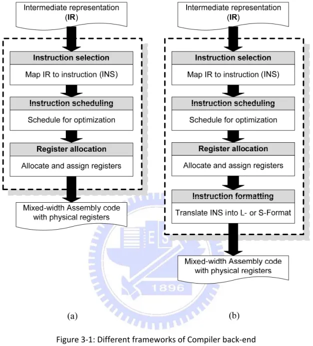
In general, traditional compiler back-ends consist of three stages, which are instruction selection, instruction scheduling, and register allocation, as shown in Figure 3-1(a). The first stage, instruction selection, maps intermediate representations (IR) to correspondent machine instructions, where the operand registers of these instructions are virtual registers. The second stage, instruction scheduling, schedules instructions for hiding possible pipeline stall to increase performance. Finally, the
However, in mixed-width ISA with mode-switch by instruction encoding, an instruction may be represented in L- or S-Formats. Therefore, an extra stage is added into compiler back-end for this kind of ISAs, as shown in Figure 3-1(b). In this compiler back-end, the first stage is instruction selection, where this stage maps an operation to temporary instruction called INS. Each INS may have L- or both L- and S-Format. The second stage, instruction scheduling does the same thing as in traditional compiler back-end. The third stage, register allocation may apply specific algorithm for mixed-width ISA or not while allocating registers. At the end, the added stage, instruction formatting, decides which format should instructions be according to their opcode and operands (e.g. register operands and immediate value). For example, if an arithmetic INS “add” has L-Format and S-Format instructions as shown in Figure 3-2, the instruction formatting stage will check whether this INS meets all limitations of S-Format instruction. If it does, then instruction formatting translates “add” into “adds”; if not, it will be formed into L-Format. Finally assembler will encode the instructions in corresponding formats.
Figure 3‐1: Different frameworks of Compiler back‐end
(a) Traditional compiler back‐end
(b) Compiler back-end for mixed-width ISA
Figure 3-2: L- and S-Format of arithmetic INS
add rd5 rs5 offset
adds rd3 rs3 rt3
rd5
L- and S-Format of add instruction
3.2 Design of HLSRA
In this section we will define some terms and structures for our design. Firstly we classify instructions of program into three types. And then we describe the data structures (e.g., register set, register active list) and priority functions which is needed in our design. At last we will describe the algorithm of our design
3.2.1 Instruction Types
In mixed-width ISA, most instructions have multiple formats. For our design, we classify instructions in program into three types.
1. L-INS (L-Format INS): L-INS is an instruction without S-Format or
which cannot be encoded in S-Format because it has exceeding immediate value.
2. S-INS (S-Format INS): S-INS is an instruction which has both L- and
S-Format, and definitely meets all limitations of S-Format, for examples, JR and NOP. JR has only one operand register so that it has enough bits for indexing register, so it can access the whole physical registers. Furthermore, NOP does not have any operands, thus, it can be encoded in S-Format definitely.
3. U-INS (Uncertain-Format INS): U-INS is an instruction which has both
L- and S-Format and can be translated into S-Format if and only if it meets limitation of operand registers.
3.2.2 Register Sets
In our design, the physical registers are divided into two sets, RegisterSetS and RegisterSetL. S-Format instruction can only access the
registers in RegisterSetS, but L-Format instruction can access the registers in
both sets. As shown in Figure 3-3, for example, if there are three bits in S-Format instruction and five bits in L-Format for register indexing, then register r0~r7 are in RegisterSetS and register r8~r31 are in RegisterSetL.
RegisterS and RegisterL represent the registers in RegisterSetS and RegisterSetL
respectively. The number of free registers in RegisterSetS and RegisterSetL are
named as FRSNS and FRSNL.
Figure 3-3: RegisteSetS and RegisterSetL
3.2.3 Register Active Lists of HLSRA
In traditional LSRA, there is only one register active list (RAL) and its size is the number of physical registers. Because HLSRA divides original register set into two separate register sets, it has to prepare two register active lists, called RALS and RALL. The size of RALS and RALL are the same as the
size of RegisterSetS and RegisterSetL. Besides, HLSRA has to maintain these
allocation. The intervals which have minimal priority in RALS and RALL are
named as mIS and mIL.
3.2.4 Priorities of HLSRA
While allocating registers to intervals, if there is no free physical register, an interval need to be spilled. In LSRA, whether an interval should be spilled or not depends on its end-point. In HLSRA, we use a different heuristic approach to decide which interval should be spilled.
In our design, the physical register set is divided into two sets, RegisterSetS
and RegisterSetL. Therefore there are two types of priorities, PriorityS and
PriorityL, for allocating registers in these register sets respectively. When there
is no free register in these register sets, priorities are used to decide which interval should be spilled. For example, while HLSRA trying to allocate register in RegisterSetS and there is no free register, it will use PriorityS to choose
spilled interval. These priorities are estimated according to the information about intervals. Since PriorityS and PriorityL are used to handle different
situation, they take different parameters into consideration.
PriorityS take three things into consideration. Firstly HLSRA want to make
as many U-INSs as possible to meet limitation of operand registers, thus it takes the number of U-INSs which use the value of the interval into consideration. In the second, if the instruction which defines the interval is U-INS, we will also consider the number of operand registers which has been assign to RegisterS of
this instruction. For example, if there are two RegisterS used for operands of the
U-INS, this U-INS will be translated into S-Format while a RegisterS is
range of the interval too. Life range presents the time that an interval will occupy a register. If a physical register is allocated to the interval whose life range is short, the register won’t be occupied too long. Therefore this register will be available soon and allocated to other intervals. Thus, the interval whose life range is shorter than others should have higher priority to acquired physical register. The priority function of PriorityS is as follow
PriorityS N S
LR ………. (1)
N1 presents the number of U-INSs which use the value of the interval;
S presents the number of operand registers which is RegisterS of the
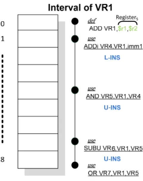
instruction which first defines the interval. LR presents life range of the interval. For example, as show in Figure 3-4, the number of U-INSs which use interval(VR1) is N1 = 3, and the number of allocated operand register
which is RegisterS is S = 2, and life range of the interval is LR = 8.
PriorityL is similar to PriorityS. First PriorityL consider the number of
instructions which use the interval; the more instructions use the value of the interval, the more spill codes will be produced if it is spilled. Second, life range of the interval is also taken into consideration like PriorityS. The
priority function of PriorityL is as follow
PriorityL NLR ………. (2)
N2 presents the number of instructions which use the interval and LR
presents life range of the interval. For examples, as show in Figure 3-4, the number of instructions which use interval(VR1) is N2 = 4 and life range of
Figure 3-4Figure 3-4: An example for priorities of intervals .
3.2.5 Spilling of HLSRA
In LSRA, the interval which has not been allocated to any physical register is spilled into memory directly. In our design, the interval which has not been allocated to RegisterS might be allocated to RegisterL. Although those U-INSs
which use this interval cannot be translated into S-Format due to the register limitation, allocating RegisterL to the interval might bring some benefit (such as
less spill code). For this reason, there are SpillS and SpillL for storing the
interval which will be spilled. The intervals in SpillS and SpillL are named as IS
and IL.
SpillS stores the interval which has not been allocated to RegisterS.
Subsequently, HLSRA will remove the interval from SpillS and try to allocate it
SpillL stores the interval which has not been allocated to RegisterL.
According to our design, this interval has no chance to get physical register so spilling pass will remove the interval from SpillL and spill it into memory.
3.2.6 Algorithm
The basic idea of our design is allocating registers in RegisterSetS and
RegisterSetL sequentially. As show in Figure 3-5, for example, while allocating
a register to an interval, such as interval (VR56), HLSRA allocates RegisterS
first. If there is no free register in RegisterSetS, HLSRA will compare PriorityS
of interval (VR56) and the interval which has lowest PriorityS in RALS (mIS).
According comparison result, the interval which has higher PriorityS will be
allocated to RegisterS. Next, HLSRA will try to allocate RegisterL to the interval
which cannot be allocated to RegisterS. If there is still no free registers, HLSRA
will select an interval in RALL with lowest priority and spill it into memory.
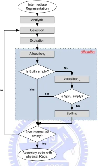
Figure 3-6Figure 3-6: Hierarchical Linear Scan Register Allocation
The overall flow chart of the HLSRA is as shown in Figure 3-6, HLSRA allocates physical registers hierarchically. At first, analysis pass scans the program to build live intervals, gets interval information needed by HLSRA (such as the number of U-INSs which use this interval, life range, etc) and stores these intervals by increasing order of their start point into interval list (LI). Then selection pass selects an interval from LI, and then expiration pass uses the start point of selected interval to expire the intervals in RALS and RALL.
After expiration pass, HLSRA starts allocating a physical register to the selected interval.
AllocationS processes the selected interval and tries to allocate RegisterS. In
the beginning AllocationS checks FRSNS to see if there are available registers in
RegisterSetS. If FRSNS is greater than zero, AllocationS will allocate one of
these free registers to the selected interval. While FRSNS is equal to zero, there
is no free register available. In this case, AllocationS has to decide which
interval should be placed into SpillS. The interval in SpillS will be processed by
AllocationL later.
To determine which interval should be put into SpillS, AllocationS chooses
the interval whose PriorityS is smallest from RALS called mIS, and compares it
with the selected interval. If PriorityS of selected interval is greater than
PriorityS of mIS, AllocationS will remove mIS from RALS and put it into SpillS,
and then the RegisterS which was occupied by mIS will be allocated to the
selected interval; otherwise the selected interval will be put into SpillS.
If SpillS is not empty after finishing AllocationS, AllocationL will remove
the interval called IS from SpillS and process it; otherwise HLSRA finish this
round of iteration.
To processing IS, like AllocationS, AllocationL checks FRSNL to see if
there are available registers in RegisterSetL. If FRSNL is greater than zero,
AllocationL will allocate one of these free registers to IS. If FRSNL is equal to
zero, there is no free register available. In this case, AllocationL selects the
interval whose PriorityL is smallest from RALL called mIL, and compares it with
the interval (IL) of SpillS. If PriorityL of IL is greater than PriorityL of mIL,
AllocationL will remove mIL from RALL and put it into SpillL, and thenthe
If SpillL is not empty after finishing AllocationL, spilling pass will be
started to spill the interval in SpillL; otherwise HLSRA finish this round of
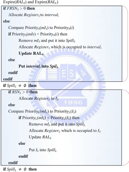
iteration. The pseudo code of HLSRA is shown in Figure 3-7.
Procedure HLSRA
// intervals stored in LI are sorted by increasing order of start point
forall intervali LI do
Calculate priorities for intervali
Expire(RALS) and Expire(RALL) if FRSNS > 0 then
Allocate RegisterS to intervali else
Compare PriorityS(mIS) to PrriorityS(i)
if PriorityS(mIs) < PriorityS(i) then
Remove mIS and put it into SpillS
Allocate RegisterS which is occupied to intervali Update RALS
else
Put intervali into SpilS
endif endif if SpillS then if RSNL > 0 then Allocate RegisterL to IS else
Compare PriorityL(mIL) to PrriorityL(IS) if PriorityL(mIL) < PriorityL(IS) then
Remove mIL and put it into SpillL
Allocate RegisterL which is occupied to IS Update RALL
else
Put IS into SpillL endif endif if SpillL then Spill IL endif endfor
Figure 3-7Figure 3-7: Algorithm of HLSRA
AllocationS
Chapter 4 Experiment
In the first part of this chapter, we will describe the experiment environment, including the instruction set architecture, used compiler back-end and benchmarks. In the second part, we will show how to decide parameters using in our experiments. At last, we will discuss the evaluation result about S-Format translation rate and influence of spill code for HLSRA.
4.1 Environment
In our experiments, we propose a pseudo mixed-width ISA with mode switch by instruction base on MIPS32/16, called MIPSe. All of the instructions have same number of formats in MIPSe and MIPS32/16, for example, instruction “add” has L- and S-Format in MIPSe as same in MIPS32/16. There is only switch mode of MIPSe different from MIPS32/16. In MIPSe, we assume that MSB of instruction op-code indicates the format of this instruction. All benchmarks used in this experiment were selected from SPEC INT2000 [11], Mibench[12], and Mediabench[13].
According to MIPS32/16 ISA and our design, the available registers in each register sets are as follows: RegisterSetS = r1 ~ r7 (r0 is used as zero in MIPS32/16, so
it cannot be used) and the number of FRSNS = 7; RegisterSetL = r10~r25 (r8~r9 is
reservedto process spill code, r26~r27 is reserved for OS kernel and r28~r31 are reserved for calling convention ) and the number of FRSNL = 16.
The Low-Level Virtual Machine (LLVM) [14] is a compiler infrastructure. It provides language- and target-independent components for building compilers. There are several targets which are supported by LLVM, such as MIPS, ARM, x86, PowerPC, etc. We modified the LLVM compiler back-end to produce the INSs with
4.2 Parameter Determination
While calculating PriorityS for each interval, HLSRA have to concern about the
number of U-INSs that use the value of the interval (N1) and the number of operand
registers which are RegisterS of the instruction which first defines the interval (S). In
another words, we have to adjust α which controls the weight between N1 and S to get
best S-Format translation rate. In our experiments, S-Format translation rate means that the percentage of the instructions which can be translated into S-Format over all instructions. The results are shown in Figure 4-1.
Figure 4-1Figure 4-1: S-Format translation rate
In the above figure, X-axis presents α value, Y-axis presents S-Format translation rate. HLSRA can achieves best S-Format translation rate when α equals one. Obviously, the number of U-INSs that use the value of the interval is the most important parameter for HLSRA to reduce code size.
52.22% 40.00% 42.00% 44.00% 46.00% 48.00% 50.00% 52.00% 54.00% 0.0 0.1 0.2 0.3 0.4 0.5 0.6 0.7 0.8 0.9 1.0 α value
S‐Format Translation Rate
4.3 Evaluation Results
In this section, we will illustrate evaluation results for HLSRA. The value of α is set to 1.0 according to the result obtained in section 4.2. As shown in Figure 4-2, we illustrate evaluation result for HLSRA and compare it to the result of LSRA. As expected, HLSRA achieves 52.22% S-Format translation rate and there is 13% more than which LSRA can make.
Figure 4-2: S-Format translation rate
As shown in Figure 4-3, number of spill codes which produced by HLSRA accounted for 8% of all instructions on the average. We can see that HLSRA has generated slightly more spill code than LSRA. The reason why this happens is described below. LSRA decides which interval should be spilled according to their end point to decrease number of spill codes. Although how HLSRA decides which interval should be spilled is similar to LSRA, HLSRA chooses interval according to their priorities to decrease code size. Therefore, HLSRA will produce more spill codes than LSRA
38.93% 52.22% 0.00% 10.00% 20.00% 30.00% 40.00% 50.00% 60.00% 70.00% S‐Format Translation Rate LSRA HLSRA
Figure 4-3: Spill code percentage
In Figure 4-4, we show the code size reduction achieved by HLSRA and compare it to the result of LSRA. The code size reduction is the number of instructions which can be translated into S-Format divide by two since each L-format instruction is twice the length of an S-format instruction.
Figure 4-4: Code size reduction
At last, we illustrate distribution of S-Format limitations in all programs which were produced by HLSRA and compare it to LSRA, as shown in Figure 4-5. The Y-axis is the percentage of instructions. In the figure, the top block, green colored, is
4.24% 8.77% 0.00% 5.00% 10.00% 15.00% 20.00% 25.00% Spill Code Percentage LSRA HLSRA 19.47% 26.11% 0.00% 5.00% 10.00% 15.00% 20.00% 25.00% 30.00% 35.00%
Code Size Reduction
LSRA HLSRAvalue is oversized. The middle block, red colored, is the percentage of instructions which cannot be formed in S-Format due to register limitation. And the bottom block, blue colored, is those instructions whose register number and immediate value are in the range of S-Format instructions.
The number of instruction which can be translated into S-Format is increased in programs processed by HLSRA. The HLSRA eases the problem of register limitation and makes 14% more instructions converted into S-Format than LSRA does. These instructions were not formed in S-Format due to register limitation originally in code produced by LSRA. By the proposed HLSRA, about 52% translation rate of S-Format instructions in programs is achieved
Figure 4-5: S-Format limitation distribution
38.93% 52.22% 0% 10% 20% 30% 40% 50% 60% 70% 80% 90% 100%
Chapter 5 Conclusions and Future Work
In this chapter, we will make conclusions and discuss some possible future works for this thesis.
5.1 Conclusion
In this thesis, we presented hierarchical linear scan register allocation (HLSRA) algorithm which allocates registers more friendly for mixed-width ISA with mode switch by instruction encoding than traditional register allocation algorithms like LSRA. Because the registers which can be accessed by S-Format instruction are allocated to intervals which have been mostly used by U-INSs, HLSRA is supposed to ease the affect brought by limitation of operand registers for code size reduction.
To achieve the goal described previously, we modify the allocation pass to fit the demand of mixed-width ISA, where allocation pass has been separated into two parts. Compared to LSRA, this modification will not increase time complexity. In addition, this design only brought neglectable overheads, such as producing a little more spill codes than LSRA and extra data structure, such as SpillS and SpillL.
Overall, our design makes S-Format instruction rate increasing to about 52% on the average. As discovered in Section 4.3, there are still 42% instructions could not be formed in S-Format due to register limitation in HLSRA. The reason why this part cannot be improved by our design is described as follow. Firstly, because there exist over eight intervals live simultaneously at many execution points in the programs, there are certainly some instructions which cannot be formed in S-Format due to register limitation. Secondly, HLSRA cannot use more efficient but complex methods, such as iterative heuristic policies, because of the demand of low compilation time for
5.2 Future Work
As we mention in section 5.1, since the design for dynamic compiler must be fast, complex optimizations are not suitable. Consequently, there are some aspects of future works for our thesis.
[1] The First possible future work is to modify HLSRA to get better S-Format translation rate. Perhaps we can modify our design with a little more time consuming policy. There are some possible modifications.
The First possible modification is adapting a little more complex priority calculation methods, for example, building interference graph for small scope of intervals and using this graph to calculate priorities.
The Second one is to split interval while spilling it. Our design will spill whole interval when it cannot get a register rather than split it. When HLSRA spills an interval, it can insert extra store instructions into this interval to split it into two intervals: previous and remain intervals, and spills remain interval only. In this way, the previous interval will not be spilled and less spill code will be produced.
[2] The second possible future work is to apply other fast optimization for increasing S-Format translation rate. As introduced in Section 3.1, there are instruction selection, instruction scheduling and register allocation in compiler-backend. In our thesis, a specific register allocation is proposed for mixed-width ISA to increasing S-Format translation rate. Therefore using a specific instruction scheduling for mixed-width ISA may achieve the same goal.
specific instruction scheduling could consider the more information while scheduling instruction, such as which formats instructions have, etc.
[3] The third possible future work is applying our design to some other commercial mixed-width ISAs with mode switch by instruction encoding, such as ARM’s Thumb-2, MIPS’ new microMIPS. We can get more information about how our design affects code size reduction and execution performance through this work. Presently we cannot do that because there are no suitable compiler backends for these ISAs.
Reference
[1] Aviral Shrivastava, Partha Biswas, Ashok Halambi, Nikil Dutt, Alex Nicolau, "Compilation Framework for Code Size Reduction Using Reduced Bit-Width ISAs (rISAs)", ACM Transactions on Design Automation of Electronic Systems, Vol. 11, No. 1, January 2006, Pages 123–146.
[2] Arvind Krishnaswamy, Rajiv Gupta, "Mixed-Width Instruction Set", Communications of the ACM, v.46, n.8, August 2003.
[3] James Gosling, Bill Joy, Guy Steele, Gilad Bracha, Java Language Specification, Addison-Wesley Longman Publishing, 2000.
[4] Tim Lindholm, Frank Yellin, Java Virtual Machine Specification, Addison-Wesley Longman Publishing, 1999.
[5] ARM Architecture Reference Manual, http://www.arm.com/
[6] MIPS32™ Architecture For Programmers, http://www.mips.com.tw/
[7] AndeStar™ ISA, http://www.andestech.com/
[8] Gregory Chaitin, "Register allocation and spilling via graph coloring", Computer Languages, Vol. 6, pp. 47-57, 1981.
[9] Massimiliano Poletto, Vivek Sarkar, "Linear scan register allocation", ACM Transactions on Programming Languages and Systems (TOPLAS), Volume 21 , Issue 5, (September 1999) Pages: 895 – 913.
[10] Andrew W. Appel, Jens Palsberg, Modern Compiler Implementation in Java, Cambridge University Press, 2002
[11] SPEC INT2000 http://www.spec.org/cpu2000/CINT2000/
[12] Mibench http://www.eecs.umich.edu/mibench/