An Energy-Efficient En-route Filtering False Data Scheme in Wireless
Sensor Networks
Ren-Junn Hwang Yu-Hang Liu
Chueh Wang
Department of computer Science and Information Engineering, Tamkang University,
Tamsui, Taipei, Taiwan 251, R.O.C
[email protected]
[email protected]
[email protected]
Abstract
- Compromised nodes could launch severalattacks in wireless sensor network. The easiest way is to fabricate a report that doesn’t happen actually or to send incorrect data. Such attack will result in not only false alarm but also the energy consumption of intermediate nodes to forward this report. There are many schemes proposed to solve this problem. They use the idea that a legitimate report must consist of several endorsements given by multiple surrounding nodes that also sense the same event. However, the compromised node also can give false endorsement on real event causing the real report to be considered a false data and be filtered out. We proposed a filtering scheme to counter some related attacks, analyzed filtering effectiveness, resiliency, storage and energy saving, and held simulation to show it is more efficient than the other solutions.
Keywords: wireless sensor network, en-route filter,
security, false data injection.
1. Introduction
The wireless sensor networks (WSNs) have been paid much attention in these years. They could apply to detect different environments such as military surveillance, monitoring forest fire, etc. The main functionality of WSNs is to detect the events in the environments and to report them to the sink. Sending fabricated reports that did not occur to the sink is called false data injection attack. SEF[12], IHA[15], LBRS[11], and PVBS[8] filter false data by the endorsements of multiple nodes, i.e., message authentication codes (MAC). Wrong endorsement attack, mentioned in PVBS[8], the attackers generating the false MACs, can be verified to filter out. We proposed a data filtering scheme to prevent above two kinds of attacks, false data injection attack and wrong endorsement attack.
2. Related work
There are some research results related to filter false data scheme. SEF[12] is the first paper to address the false data injection attack. IHA[15], LBRS[11] and PVBS[8] propose improved schemes based on the framework of the SEF. However, the main drawback in SEF is that if the adversary has collected a number of compromised nodes anywhere, the adversary can claim events happening in any place without the risk of being filtered. In other words, the resiliency in SEF is not well. IHA[15] also has poor resiliency. If the attacker collects more than t compromised nodes, the schemes will fail.
Besides, all keys are derived from the several secret keys, so it must ensure the initial phase is secure. The security problem is also in PVBS[8], because all the keys are assigned to each node by the sink after cluster formation. We comment it impractical since it communicates a lot to transmit keys and it must ensure the transmission in secure channel. What’s worse, if some of clusters changes, the sink must assign keys again.
3. Preliminaries
3.1 Assumption and the network model
Consider a sensor network of a large number energy-constrained sensor nodes and a resource-abundant sink. Sensor nodes do not move after deployment. The sensor nodes are grouped into exclusive clusters by a cluster model. The sensor network contains multiple clusters. The sensor nodes are deployed in high density, so that each event can be detected by many sensors simultaneously. There are at least s sensors detecting the same event in the cluster. It is a basic assumption for many security-sensitive WSNs applications, such as [7] [8] [9] [11] [12] [14] [15].
In a cluster, one node is elected to be the cluster-head (CH), and CH assigns a unique ID to its member, which the ID is only used in this cluster. After cluster formation, every node should know which cluster it belongs to, who CH is, and what its ID is in this cluster. There are many ways to form clusters, elect CHs, and get unique ID, such as [4] [6] [13].
We assume every CH could know the routing path to the sink. Especially, the CH could know each relay node on the path and the number of hops between the relay node and the CH. There are many ways to achieve it, such as DSR[5]. On the same issue, PVBS[8] also makes the same assumption.
3.2 The attacker model
We assume that the attacker may compromise a node by physically capture or other ways and then obtain the security information installed in the node. The attacker cannot compromise the sink since the protection at the sink is powerful enough. The attacker will use the compromised nodes to inject false reports into the wireless sensor network and make the damages as mentioned before. They also attack the real report: when a sensor node needs endorsements of other nodes on a real event, the compromised nodes give false endorsements.
We assume the attacker would launch this attack to injure the real report.
3.3 The design objectives
For a sensor network with above assumptions and model, the proposed scheme provides the following functionality: 1. Filter out the false report, namely, false data injection attack, caused by compromised nodes or other unexpected factors. 2. Reduce the damage which compromised nodes give false MACs on a real report, namely, wrong endorsement attack. 3. The false report could be filtered out en-route by the proposed scheme to reduce the energy consumption of the intermediate nodes to forward false reports. 4. More efficient than the related solutions [8] [11] [12] [15].
4. The proposed scheme
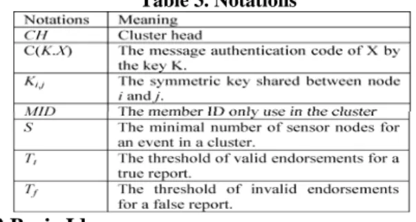
4.1 Notations
Table 3. Notations
4.2 Basic Idea
To solve the problem that compromised nodes inject the false data arbitrarily, the report to describe an event needs some endorsements given by sensor nodes, i.e. the sensor nodes give reporter the MACs of this report generated by their secret keys individually. When the report is forwarded on the routing path to the sink, if the relay node keeps the same secret key, it will verify the validity of the MACs. If there are some invalid MACs, they will drop this report since it maybe a false data injection attack by compromised nodes. This is the general en-route filtering framework used in [8] [12] [11] [15] and ours. In [12], it is dependent on the probability of key sharing. We introduce the Blom’s key establishment scheme [1] to ensure any two nodes would share a pairwised key.
The CH of the proposed scheme should publish a message. The message includes the verifiers’ IDs, i.e., the intermediate sensor nodes, are chosen from the CH’s routing path to the sink. We name this message “verifier list”. CH has duty of maintaining its verifier list for some situation, e.g. the using times of the verifier list exceeds the predefined threshold, or the CH has gotten some warnings from the sink to update. By verifier list, the sensor node could find out a verifier’s ID to derive a shared key to generate a MAC of its sensing data. On the other hand, when a report is forwarding to the sink, the relay node could know whether it is the verifier or not and which shared key it should derive by the information of the report.
4.3 Blom’s scheme
Now, we briefly introduce Blom’s scheme [1] here and readers can refer to [2] [3] for details. It enables each pair of nodes in the network to establish a pairwised key. It has the property called “λ-secure”, where λ is a security parameter. It means that if no more than λ nodes are compromised, all other communication links of non-compromised nodes remain secure.
A symmetric matrix KN×N includes all the pairwised
keys of N nodes, which each element kij or kji is the key
shared between node i and node j. The matrix K is derived from (DG)TG, where the matrix D(λ+1)×(λ+1) is
symmetric and secret, and the matrix G(λ+1)×N is public.
The matrix AN×(λ+1) created as A= (DG)T is also a secret
matrix. Before deployment, each node i stores the ith row of the matrix A and the ith column of matrix G. After deployment, each pair of nodes i and j can compute a pairwised key kij = kji by exchanging their columns and
computing the dot product of their own row and the column of the other’s. It is easy to see that:
K=A.G=(DG)T.G=G TD T.G=G TD.G=(A.G)T=KT,
Due to the matrix K is a symmetric, each pair of nodes can derive the same key.
The public matrix G is also designed to be a
Vandermonde matrix derived from a seed, which is mentioned in [10]. It reduces the communication and storage overhead but needs more computation. What the node i needs to store are the row i of matrix A and the seed. The node which wants to get the columns of other nodes can use the seed to derive it. Finally, if any node i want to establish a pairwised key with other node j, the node i only needs to know the ID of node j.
4.4 Proposed scheme
The proposed scheme includes five phases: initialization phase, publishing verifier list phase, report generation phase, en-route filtering phase and sink verification phase.
Initialization phase: Each sensor is assigned a
unique ID and key material to establish key by Blom’s scheme. Each sensor starts to cooperate with its neighbors to form a cluster. The CH is elected, and assigned a unique ID to its members; the ID is used only in this cluster.
Publishing verifier list phase: The CH has to
determine and publish a verifier list. This verifier list includes IDs of the intermediate sensor nodes which are chosen by the CH. The CH also arranges these IDs randomly. The CH will alter and publish the verifier list when the verifier list has been used exceeds the predefined threshold, or the CH has got sink’s warnings to update.
To determine the verifier list, the CH establishes a table first to maintain four factors of each sensor node on its routing path. The four factors are: Hops, Times,
Warning, and Sum. Hops, is hops from the node to the CH. Times, is times the nodes has been chosen into the verifier
list. The factor of each node is set to zero initially. When a node is chosen into the verifier list, this factor of the
node will be increased by the CH. Warning, is warnings have been received from the sink. When the CH receives the warnings, it will increase the factor of corresponding nodes. Sum, is the weighted sum of above three factors. The weights of above three values are hopsWeight,
timesWeight, warningWeight, respectively.
Sum = Hops×hopsWeight + Times×timesWeight +
Warning×warningWeight
CH gets priorities of nodes by comparing the values of
Sums. The smaller the Sum is, the higher the priority is. Sum_MAX, the upper-bound of Sum is defined, i.e., if Sum
of a relay node is larger than Sum_MAX, CH will no longer choose it into verifier list. When the CH needs to determine and publish a new verifier list, it will compare the value of Sum of each node in the table. After published verifier list, CH increases Times of each node in the verifier list and recomputed the value of Sum.
Such design is very flexible for the different users to set the weight according to their requirements. By increasing hopsWeight, the verifiers might be closer to the CH; by increasing timesWeight, the percentage of each node chosen might be more average. In our recommendation, we set the values of hopsWeight and
warningWeight to be equal to the number of hops
between the CH and the sink and timesWeight to 1. If Sum of some nodes are equal, we need to
compare the other values: Warning→Hops→Times. There is also a case that we couldn’t find out s nodes e.g. the CH is too close to the sink or the network has been running a long time.
Report generation phase: When an event occurs,
there are three important roles collaborating to generate the final report: (1) the sponsor, who is the first node senses the event; (2) the endorsers, who are the nodes also senses the same event; (3) the CH, who is the role to collect sensing data and endorsements from its members. Each sensor node determines its verifier ID from the verifier list by
r = MID mod s
where MID is the ID of the node i using in the cluster. The node i will take r-th ID from the published verifier list. Without loss of generality, we assume the verifier of the node i is the node j in the following statements. By this ID, the node i can derive a shared key, Ki,j , with the
node j. The shard key will be used to generate an MAC for the event report. The detailed steps of this phase are as the following:
Step 1: When an event happens, the sponsor broadcasts the message:
Reading, i, j, C(Ki,j, Reading) where i, j is IDs pair of sensor node and verifier node, Ki,j
is the pairwise key shared between node i and j , C(.) is the MAC function . Reading is the sensed data of the event.
Step 2: After the other nodes receive this message, they check it and determine whether giving the endorsements or not, the detailed steps are as follows:
2-1: The endorsers compare the broadcasted reading with its reading.
2-2: If the difference is within some predefined error range, the node will generate and send the following message to the CH.
i, j, C(Ki,j , Reading)
where C(Ki,j, Reading) is the endorsement of the Reading.
Step 3: The CH has received the data and the endorsements from different nodes, the CH performs the following sub-steps to check messages and determine whether generating the event report to sink or not.
3-1: The CH first checks whether each IDs pair (i, j) is valid or not by equation (2). If any pair is invalid, it will drop this data immediately.
3-2: After filtering out the invalid data, if the CH has received at least s distinct data from different nodes, it will aggregate them to be an event report and send it to the sink as the following format:
Reading||{i, j, C(Ki, j, Reading)}||right||wrong
where { } is a set including each IDs pair and MAC sent by each endorser; right is number of verified valid MACs;
wrong is number of invalid MACs. right and wrong are
initially zero and maintained in the forwarding process of the en-route filtering phase.
En-route filtering phase: When a sensor node
receives an event report in the forwarding process, it will do the following to decide to forward or drop it.
Step 1: Check the format of this report. If invalid, drop this report and terminate this phase; otherwise, continue Step 2.
Step 2: Check whether it is one of verifiers of this report by examining each IDs pair (i, j). If yes, continue Step 3 to do more checks; otherwise, drop the report and terminate this phase. .
Step 3: Check whether the value of right reaches the threshold Tt or not. If reaches, forward it; otherwise,
continue Step 4 to determine whether verifying the report or not.
Step 4: Determine to verify or forward the report by the Algorithm 1. If it doesn’t satisfy the condition, it forwards the report; otherwise, continues Step 5 to verify the report.
Step 5: Derives the Ki,j by taking the ID i into Blom’s
scheme. Another MAC of the report is generated by this Ki,j and compared to the corresponding MAC in the event
report.
Step 6: By comparison, increase the value of right or wrong. If the value of wrong reaches the threshold Tf,
drop this report; otherwise, forward this report.
In Step 4, we don’t force the node to verify unless it has sufficient energy. The reason is MAC verification takes computational cost. If the energy of the node is low, we hope the node to keep its energy to survive. Even if the energy is medium, we hope the node consider the necessity of verification. i.e., how many MACs verified. If there is only few MACs have been verified, the node needs to do the verification of this report. The Algorithm shows the conditions of deciding the verification.
Algorithm 1. VerifyCondition()
if energy > energyEnough then verify Report; else if energy <energyPoor then forward Report;
else if (right + wrong) ≤ fewVerified then verify Report;
else forward Report;
The user must predefine the value of these three parameters: energyEnough and energyPoor are lower bound and upper bound of energy. fewVerified is the threshold, which the node does the verification if the energy of the node is medium and the number of verified MACs isn’t more than it. As shown in the algorithm 1, the relay node compares the value of fewVerified to the sum of right and wrong. Because this sum also means the number of MACs have been verified.
Sink verification phase: When the sink receives
the report, it checks the format of the report as relay node does and whether endorsers belong to the same cluster or not. It is also able to verify all the MACs in the report and make the decision. In this phase, the sink plays a role as final guard.
If some node is used too many times in a period, it will send the warning to each CH against choosing the node. The value of the warning depends on how long time the sink wants the node to be free. If the sink wants the node not to be chosen forever, it will send the Sum_MAX to each CH.
5. Analysis
Here we analyze the efficiency, resiliency, and key storage of our scheme.
5.1 Filtering effectiveness
There are many factors affecting the filtering effectiveness. Two most important of them are (1) the probability that attacker could cheat all the verifiers; (2) the positions of the verifiers.
If there is only one compromised node, the probability p1 that attacker could cheat all verifiers is:
1 1
1
, where is the length for a MAC in bits. 2 s e p e − ⎛ ⎞ = ⎜ ⎟⎝ ⎠
If we choose a secure hash function to generate MACs, the probability p1 is negligible. There is also
another case that attacker has more than one compromised nodes, we will discuss in the section 5.2.
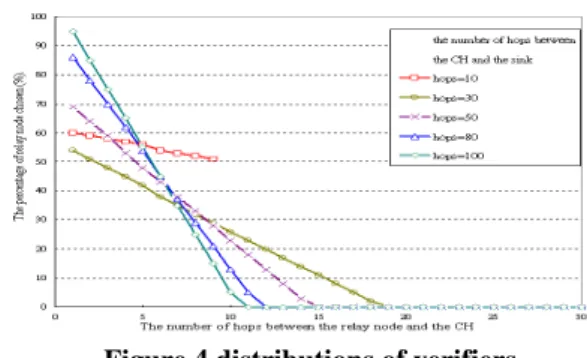
The positions of verifiers depend on the verifier list which is published by the CH. If the chosen nodes are near the CH and have enough energy, the false report must be filtered out in first few steps. This is what we need because it reduces the communication overhead of relay nodes. However, if we always choose the same nodes to be verifiers, these nodes will consume much energy on computation. PVBS[8] and LBRS[11] are also in this situation. As shown in figure 4, we gather statistics on the percentage of each relay node chosen to be verifier when the verifier lists are published 1000 times by the different CHs which are different distance to the sink. We can see that most of verifiers are only 10 hops to the CH but some verifiers are not. We also simulate how the verifiers filter out the false reports in section 6.
Figure 4 distributions of verifiers
5.2 Resiliency
Consider the resiliency to increasing number of compromised nodes. If there are cm compromised nodes comes from the same cluster, we can compute the probability p2 that the false report could cheat all verifiers
is:
2
1
, where is the length for a MAC in bits. 2 s cm e p e − ⎛ ⎞ = ⎜ ⎟⎝ ⎠
Thus, the probability p2 could be ignored unless the
attacker has compromised s nodes in a cluster.
5.3 Key storage
In our scheme, the key storage of each node depends on the λ-size of the matrix which used in Blom’s scheme. Thus, the scale of nodes in the network doesn’t affect the key storage of each node directly. However, in other scheme such as SEF[12], the probability of key sharing is based on how many keys they have. If we want to increase the filtering effectiveness of SEF, the probability of key sharing between each pair of sensor nodes must increase. It results in not only the increased number of keys loaded for each sensor node, but also more disclosure of secret information for each compromised node. Besides, the number of key storage in LBRS[11] and PVBS[8] are low. However, LBRS must assume no compromised nodes happen until the location discover and key assignment phase finish, and PVBS takes very high cost on communication since the sink must send the key for each node. If the network size is large, PVBS is impractical.
6. Simulations
We use some simulations to further verify our analysis. In our simulation, we focus on (1) filtering effectiveness (2) resiliency (3) energy savings. We use the following parameters in our simulation:
Table 4. Parameter setting
6.1 Filtering effectiveness
effectiveness of our scheme. As shown in table 5, we present the filtering effectiveness under the following cases:
Table 5. The simulation of filtering effectiveness
6.1.1. Case A. As figure 5, we could see that the mean of
hops that false reports dropped is pretty few even in the case cm = 4. Comparing with SEF, our scheme has better filtering effective and doesn’t change so much in the increasing cm.
Figure 5 The filtering effectiveness (sufficient energy and Tf = 1)
6.1.2. Case B. As shown in figure 6, we simulated with
medium energy.
Table 6. Parameter setting in energy.
Notations Value
energyEnough 75% energyPoor 25% fewVerified 2
It shows the filtering effectiveness of our scheme is better than SEF slightly in the case cm=1,2,3, but worse in the case cm=4. However, the attacker wants to achieve the case cm=4 in our scheme is more difficult than SEF since the CH and the sink will more check the endorsements come from the same cluster or not.
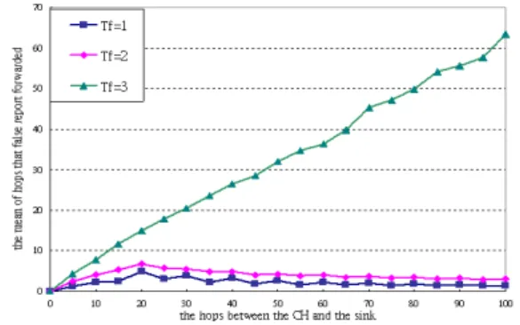
6.1.3. Case C. As shown in figure 7, we simulate with
defense of the wrong endorsement attack. In other words, we vary the value of Tf, which means the tolerance to
invalid endorsements. Obviously, the effect of increasing
Tf must make the filtering effectiveness down. But our scheme can filter out the false reports in 10 hops even in the case of Tf = 3.
Figure 6 The filtering effectiveness (middle energy and Tf = 1)
Figure 7 The filtering effectiveness (different Tf and
sufficient energy)
6.1.4. Case D. In figure 8, we simulated both attacks with
medium energy. Filtering effectiveness doesn’t be affected much when Tf =3, because fewVerified = 2. If the
relay nodes only have medium energy, there are only three of the MACs will be verified at most. Thus, if one of this three MACs is verified valid, the report will be forward to the sink due to the value of wrong can’t reach three. In this result, the mean of hops that false report forwarded will increase a lot.
Figure 8 The filtering effectiveness (different Tf and
middle energy)
6.2 Resiliency
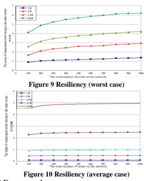
In this section, we gather the statistics of compromised nodes in the same cluster when the attacker has randomly compromised some nodes. We also take the mean of the results of running 1000 times. The number of nodes in a cluster is 10, and varies the number of nodes in the network. Two cases, worst and average case are shown in figure 9 and figure 10, respectively.
What we care is if there are more than 5 compromised nodes belong to the same cluster due to s =5. As shown in the figure 9, the attacker must compromise more than 20% of nodes in the network. On the other hand, as figure 10, the attacker must compromise more than 50% of nodes in the network. It shows the high resiliency of our scheme in the case s = 5. The user can use this simulation to determine how large the value of s should be for different environment.
Figure 9 Resiliency (worst case)
Figure 10 Resiliency (average case)
6.3 Energy saving
Even though, we spend more energy on generating the MACs, but it’s negligible. It takes 15 μJ computing a RC5-based MAC in [12]. Therefore, we want to show the energy saving is on communication.
The way of our simulation is to compute the energy consumption ratio between protected and unprotected scheme. We assume the energy consumption of each hops between two nodes is equal. So the ratio is proportional to hops. In figure 11, it shows our scheme protected could save much of energy because it can filter out the false report in first few hops. Even in the worse cases: (Tf =1 & cm=4) and (Tf =2 & cm=2), they still can save 50% energy if the number of hops between the CH and the sink is greater than 10.
7. Conclusions
We proposed a scheme to counter the compromised nodes generating the report on false event or giving the false endorsements on real event.
Blom’s scheme in the key establishment is used to generate MACs. Additionally, we provide a way to arrange MAC pair which should be generated and verified. In our analysis and simulations, we showed this approach has better filtering effectiveness, resiliency and the energy consumption than the past solutions [8] [11] [12] [15].
Figure 11 Energy saving (for communication)
ACKNOWLEDGEMENTS
This work was partially supported by the iCAST project sponsored by the National Science Council, Taiwan, under the grants no. NSC97-2745-P-001-001
Reference
[1]R. Blom, “An optimal class of symmetric key generation system,” in Eurocrypt’84, Lecture Notes in Computer Science, VOL. 209, Springer-Verlag, pp. 335-338, 1985.
[2]W. Du, J. Deng, Y. S. Han, P. K. Varshney , “A Key Predistribution Scheme for Sensor Networks Using Deployment Knowledge” IEEE Transactions on Dependable and Secure Computing, VOL. 3, NO. 1, pp.62-77, 2006. [3]W. Du, J. Deng, Y. S. Han, P. K. Varshney, J. Katz, A. Khalili,
“A Pairwise Key Predistribution Scheme for Wireless Sensor Networks,” ACM Transaction on Information and System Security, VOL. 8, NO. 2, pp. 228-258, 2005.
[4]W.R. Heinzelman, A. Chandrakasan, H. Balakrishnan, “An Application- Specific Protocol Architecture for Wireless Microsensor Networks,” IEEE Transactions on Wireless Communications, VOL. 1, NO. 4, pp. 660-670, 2002.
[5]D. Johnson, D.A. Maltz, J. Broch, “The dynamic source routing protocol for mobile ad hoc networks (Internet-Draft),” mobile ad hoc network (MANET) working group, IEFT (1999).
[6]V. Kawadia, P. R. Kumar, “Power Control and Clustering in Ad Hoc Networks,” In INFOCOM, 2003.
[7]S. Kumar, T. H. Lai, J. Balogh, “On k-coverage in a mostly sleeping sensor network,” International Conference on Mobile Computing and Networking, pp.144-158, 2004.
[8]F. Li, J. Wu, “A probabilistic voting-based filtering scheme in wireless sensor network,” International Wireless Communications & Mobile Computing Conference, pp.27-32, 2006.
[9]M. Ma, “Resilience of sink filtering scheme in wireless sensor networks,” Computer Communications, VOL. 30, NO. 1, pp. 55-65, 2006.
[10]F. J. MacWilliams, N. J. A. Sloane, “The Theory of Error-Correcting Codes.” Elsevier Science, New York. 1977. [11]H. Yang, F. Ye, Y. Yuan, S. Lu, W. Arbaugh, “Toward
resilient security in wireless sensor networks,” Proceedings of the 6th ACM International Symposium on Mobile ad hoc Networking and Computing (MobiHoc), pp. 34-45, 2005. [12]F. Ye, H. Luo, S. Lu, L. Zhang, “Statistical En-route
Filtering of Injected False Data in Sensor Networks,” IEEE Journal on Selected Areas in Communications, VOL. 23, NO. 4, pp.839-850, 2005.
[13]O. Younis, S. Fahmy, “Distributed Clustering in Ad-hoc Sensor Networks: A Hybrid, Energy-Efficient Approach,” In INFOCOM, 2004.
[14]Y. Zhang, W. Liu, W. Lou, Y. Fang, “Location-Based Compromise-Tolerant Security Mechanisms for Wireless Sensor Networks,” IEEE Journal on Selected Areas in Communications, VOL. 24, NO. 2, pp. 247-260, 2006. [15]S. Zhu, S. Setia, S. Jajodia, P. Ning, “An Interleaved
Hop-by-Hop Authentication Scheme for Filtering False Data in Sensor Networks,” in IEEE Proceedings of Symposium on Security and Privacy, pp.259-271, 2004.