透鏡陣列之擴散片
57
0
0
全文
(2) 透鏡陣列之擴散片 Diffuser Film with Surface Relief of Lens Array 研 究 生: 蕭舜庭 指導教授: 田仲豪. Student: Shun-Ting Hsiao Advisor: Dr. Chung-Hao Tien. 國立交通大學 電機學院 光電工程學系 顯示科技研究所 碩士論文. A Thesis Submitted to Display Institute & Photonic Department College of Electrical Engineering Science National Chiao-Tung University in Partial Fulfillment of the Requirements for the Degree of Master In Display Institute December 2007 Hsin-Chu, Taiwan, Republic of China.. 中華民國九十六年十二月.
(3) 透鏡陣列之擴散片 研究生:蕭舜庭. 指導教授:田仲豪 博士. 國立交通大學 光電工程學系 顯示科技研究所. 摘要 擴散片是個光穿透的元件,凡是能重新分配光分布的膜片都可定義為擴散 片。此篇論文中,我們提出兩種不同功能的透鏡陣列之擴散片。光束形變擴散片 能依其表面的方形透鏡形狀來產生方形的光場,此特性可運用於掃描式背光的分 區概念中。另一種功能為應用於一般的背光模組中,透鏡陣列擴散片能同時具有 集光和擴散光的效果,可代替傳統的增益片和擴散片。. i.
(4) Diffuser Film with Surface Relief of Lens Array. Student: Shun-Ting Hsiao. Advisor: Dr. Chung-Hao Tien. Department of Photonics & Display Institute National Chiao Tung University. Abstract Diffusing film, which is an optically transmissive component, is provided to redistribute the propagating light. In this study, we proposed two functions of diffusing film with surface relief of lens array. Beam shaping film with spherical micro-lens array produces the square beam shaping pattern applied to the division areas in the scanning backlight module. A novel diffuser, lens array film, performs dual functions of light collection and diffusion and is proposed to combine and replace BEFs and diffusers in the backlight module.. ii.
(5) 誌謝 本論文能順利完成,首要感謝的是我指導老師田仲豪教授,兩年 來的教導和啟發,讓我在學習研究和處事方法上獲益良多,在此致上 最誠摯的謝意。實驗室的學長姐,小陸、健翔、進哥、哲哥、楠哥、 柏宏學長和璧如學姐,在這兩年中提供不少寶貴的意見,並教導我許 多研究學習方法。也很謝謝姚哥、世瑋、子翔和永志在課業上給我鼓 勵和支持,還有學弟們帶給我很多的歡樂。最後要感謝我家人,有他 們的支持我才能順利完成學業,謹以本文獻給家人及關懷我的人。. iii.
(6) Table of Contents Abstract (Chinese) ----------------------------------------------------------------------------- i Abstract (English) ----------------------------------------------------------------------------- ii Table of Contents ----------------------------------------------------------------------------- iv Figure Caption -------------------------------------------------------------------------------- vi Table Caption --------------------------------------------------------------------------------- ix. Chapter 1 Introduction ----------------------------------------------------------------------- 1 1.1 Preface ------------------------------------------------------------------------------------ 1 1.2 Conventional Films in the Backlight Module --------------------------------------- 1. Chapter 2 Radiometry and Photometry -------------------------------------------------- 5 2.1 Solid Angle ------------------------------------------------------------------------------- 5 2.2 Radiometry ------------------------------------------------------------------------------- 6 2.3 Photometry ----------------------------------------------------------------------------- 10 2.4 Bidirectional Reflection and Transmission Distribution Function -------------- 12. Chapter 3 Beam Shaping Diffuser Film ------------------------------------------------- 14 3.1 Beam shaping Film with Lens Array ------------------------------------------------ 14 3.2 Scanning Backlight Module ---------------------------------------------------------- 16 3.3 Simulations ----------------------------------------------------------------------------- 18 3.3.1 One-sided Lens Array ------------------------------------------------------------ 18 3.3.2 Both-sided Lens Array ----------------------------------------------------------- 21 3.3.3 Applying to the Backlight Module --------------------------------------------- 25. iv.
(7) Chapter 4 High Gain Diffuser Film ------------------------------------------------------ 27 4.1 Light Diffusion and Collection ------------------------------------------------------ 27 4.2 Film Structures ------------------------------------------------------------------------- 28 4.3 Simulations ----------------------------------------------------------------------------- 32 4.3.1 Periodic Arrangement ------------------------------------------------------------ 32 4.3.2 Random Arrangement ------------------------------------------------------------ 36. Chapter 5 Conclusion ----------------------------------------------------------------------- 40. References ------------------------------------------------------------------------------------- 41. Appendix -------------------------------------------------------------------------------------- 43. v.
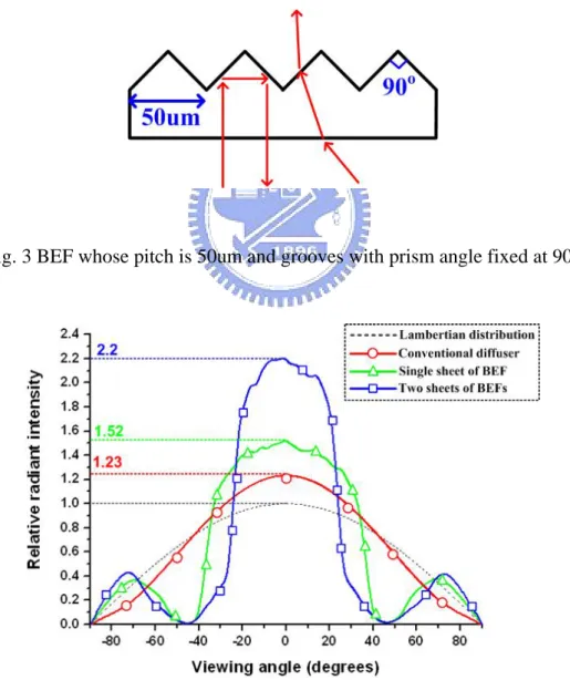
(8) Figure Caption Fig. 1 Conventional backlight module ------------------------------------------------------- 2 Fig. 2 The particles on the diffuser ----------------------------------------------------------- 3 Fig. 3 BEF whose pitch is 50um and grooves with prism angle fixed at 90° ----------- 3 Fig. 4 Light enhancement of conventional films in the BLM ---------------------------- 3 Fig. 5 Solid angle ------------------------------------------------------------------------------- 5 Fig. 6 Solid angle in the spherical coordinates --------------------------------------------- 6 Fig. 7 Irradiance -------------------------------------------------------------------------------- 7 Fig. 8 Radiant intensity ------------------------------------------------------------------------ 8 Fig. 9 Radiance --------------------------------------------------------------------------------- 8 Fig. 10 the angular distribution of Lambertian radiator ----------------------------------- 9 Fig. 11 Visible response of different wavelength ----------------------------------------- 11 Fig. 12 The definition of BRDF ------------------------------------------------------------- 13 Fig. 13 BTDF of conventional diffuser ---------------------------------------------------- 13 Fig. 14 Beam shaping film which controls light propagation and directing it to form a specified shape --------------------------------------------------------------------- 14 Fig. 15 The micro-structures of Engineered Diffuser ------------------------------------ 15 Fig. 16 Examples of LED light control with Engineered Diffusers -------------------- 15 Fig. 17 Motion blur of a car moving -------------------------------------------------------- 16 Fig. 18 The scanning way of the divided light guides ------------------------------------ 17 Fig. 19 The divided wedge light guide designed for large size panel ------------------ 17 Fig. 20 Direct type scanning backlight module with beam shaping diffuser ---------- 18 Fig. 21 The periodic lens array which are (a) square, (b) triangular and (c) hexagonal result in the beam shaping patterns (d), (e) and (f), respectively. ----------- 19. vi.
(9) Fig. 22(a) The spherical surface lens (b) The lens sculptured into square shape ----- 19 Fig. 23 The bean shaping patterns of the lens array diffusers with different sags observed on the plane located at focal distance of f and 100f --------------- 20 Fig. 24 Spherical aberration ----------------------------------------------------------------- 20 Fig. 25 The uniformities and the profiles of the beam shaping patterns of the diffusers with different numbers of lens --------------------------------------------------- 21 Fig. 26(a) One-sided lens array (b) both-sided lens array ------------------------------- 22 Fig. 27 Imperfect beam shaping pattern ---------------------------------------------------- 22 Fig. 28 The patterns resulting from the perfect and imperfect collimated light which passes through the one-sided square lens array film -------------------------- 23 Fig. 29 The opposite lens correcting the red light with an inclined angle ------------- 24 Fig. 30 The patterns resulting from the perfect and imperfect collimated light which passes through the one-sided square lens array film -------------------------- 24 Fig. 31 Two one-sided lens array films put together ------------------------------------- 25 Fig. 32(a) The profile of the direct type BLM (b) the beam shaping pattern (c) 9 LED light sources ------------------------------------------------------------------------ 26 Fig. 33(a) The conventional backlight module (b) lens array film replacing BEFs and diffuser in the BLM ---------------------------------------------------------------- 27 Fig. 34 Surface types depending on conic constants in Table 1 ------------------------- 29 Fig. 35 Examples of spherical and aspheric surfaces as r decreases ------------------- 30 Fig. 36(a) An aspheric surface lens (b) an aspheric surface lens sculptured into square shape --------------------------------------------------------------------------------- 31 Fig. 37(a) The lens array film arranged by periodic square lens array (b) the lens array film subject to random lens pitches ---------------------------------------------- 31 Fig. 38(a) The profiles of hyperboloidal surfaces (b) The angular intensity distributions of HLAF with different ARs -------------------------------------- 33 vii.
(10) Fig. 39(a) The profiles of paraboloidal surfaces (b) The angular intensity distributions of PLAF with different ARs ------------------------------------------------------ 33 Fig. 40(a) The profiles of spherical surfaces (b) The angular intensity distributions of SLAF with different ARs --------------------------------------------------------- 34 Fig. 41 The enhancements in the range of conic constants of -2.5~0.5 and the corresponding ARs ----------------------------------------------------------------- 35 Fig. 42 The angular intensity distributions of PLAF compared with conventional diffuser and BEF ------------------------------------------------------------------- 36 Fig. 43 The angular intensity distributions of PLAFs and conventional diffuser ----- 37 Fig. 44(a) BTDF of conventional diffuser and (b) randomly-arranged PLAF -------- 38. viii.
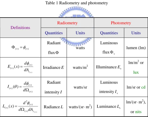
(11) Table Caption Table 1 Radiometry and photometry ------------------------------------------------------- 10 Table 2 Conic constants and surface types ------------------------------------------------- 28 Table 3 Transmittance of BEF and PLAF -------------------------------------------------- 39. ix.
(12) Chapter 1 Introduction 1.1 Preface Diffusing film, which is an optically transmissive component, is provided to redistribute the propagating light. A film is regarded as a diffusing film whatever functions it possesses when light passes through, such as light collection, diffusion or beam shaping. In general, the micro-structures of diffusing film control the propagating direction of light for specified distribution. In this study, diffusing films with surface relief of lens array are applied to the backlight module (BLM). It is expected that diffusing films are able to replace the conventional components in the BLM in order to reduce the production cost.. 1.2 Conventional Films in the Backlight Module The liquid crystal display (LCD) industry develops quickly in the recent years. The device supplying illumination of LCD is the backlight module. Fig. 1 shows the conventional BLM. Light extracting from the light source enters the wedge type light guide. After emitting from the light guide, light propagates through diffuser and is scattered into all directions of the hemi-spherical space. Then the scattered light is redirected by the light-collecting films and collected to the normal direction. These optical films above the light guide are employed to promote light uniformity and collimation in the BLM. The protective diffuser as shown in Fig. 1 preserves BEF from damage and reduces the periodic effect such as Moiré effect resulting from BEFs and the cells of liquid crystal.. 1.
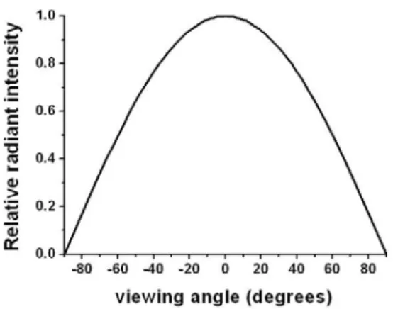
(13) Fig. 1 Conventional backlight module. In the backlight module, diffuser scatters light extracting from the light guide in order for light uniformity of the whole panel. Although the micro-structures of the light guide have the similar function of light diffusion, the light uniformity of the light guide is not sufficient. Diffuser is able to compensate the light guide for insufficient light uniformity. Conventionally, bead-coating and micro-structure embossing diffusers are applied in the BLM to increase the uniformity [1, 2]. Fig. 2 shows the particles on the surface of a bead-coating diffuser, whose diameter is about 50um. In addition, the conventional bead-coating diffuser can supply about 23% enhancement of brightness along the normal direction, as shown in Fig. 4, where the x-axis is the viewing angle and the y-axis is the relative radiant intensity. The dotted line represents the lambertian distribution light source as the reference, in which the maximum intensity is normalized to be 1. Diffuser with micro-sized bead functions both scattering and collection.. 2.
(14) Fig. 2 The particles on the diffuser. Fig. 3 BEF whose pitch is 50um and grooves with prism angle fixed at 90°. Fig. 4 Light enhancement of conventional films in the BLM. 3.
(15) Conventionally, two orthogonally-arranged brightness enhancement films (BEFs) with prismatic surface structures are treated as the light-collecting films to enhance the on-axis intensity along the normal direction [3, 4]. BEF has grooves with prism angle fixed at 90° and the pitch of the grooves is 50um, as shown in Fig 3. Fig. 4 indicates that one BEF enhances on-axis intensity achieved to 152%, and two orthogonally- arranged BEFs provide 220% intensity. Due to the periodic structures of BEFs, Moiré effect, which is the interference between BEFs and LC cells, is easily observed by the human eyes. Another diffuser above BEFs or the micro-structure film whose periodic structure is randomized are provided to reduce Moiré effect [5].. 4.
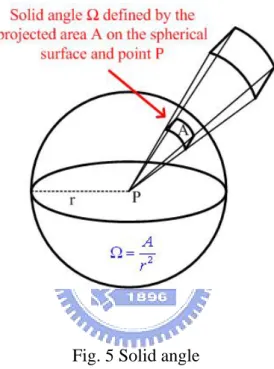
(16) Chapter 2 Radiometry and Photometry 2.1 Solid Angle. Fig. 5 Solid angle. Solid angle ( Ω ) whose vertex is located in the center of a sphere cuts off an area on the surface of the sphere, as shown in Fig. 5. Solid angle, whose unit is steradian (sr), is defined as below:. Ω=. A , r2. (1). where A is the cut-off area of the sphere and r is the radius of the sphere. In addition, Fig. 6 indicates the solid angle in the spherical coordinates and its representation is as follows: 5.
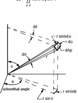
(17) dΩ =. dA r sin θ dφ ⋅ rdθ = = sin θ dφ dθ ( sr ) , r2 r2. (2). Where φ is the azimuthal angle in the x-y plane and θ is the polar angle along the z axis. Then, the solid angle can be obtained by integrating equation (2).. Ω = ∫∫ sin θ dφ dθ .. (3). φθ. Fig. 6 Solid angle in the spherical coordinates. 2.2 Radiometry. In optics, Radiometry is the measurement of optical radiation, which is electromagnetic radiation within the wavelengths range between 0.01um and 1000um; in other words, that includes the regions commonly called ultraviolet, visible and infrared. In general, the unit of radiant flux φ of measurement is watt. In the field of backlighting, radiometry is often regarded as an adequate way to characterize the optical behavior. For example, the distribution of the extracting light and the property. 6.
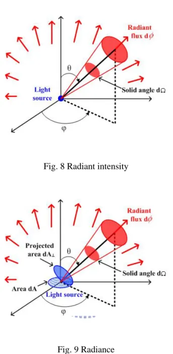
(18) of the light source can be described by radiometry. Irradiance E, which is the area density of radiant flux, describes light distribution on the received plane. The definition is the radiant flux per unit area of a specified surface which the propagating light is incident on or passing though, as shown in Fig. 7. The representation of irradiance is expressed as below:. E ( x) =. dφ (watt/m 2 ) . dAc. (4). Fig. 7 Irradiance. Radiant intensity I, which is the solid angle density of radiant flux, describes the characteristics of light source such as a point source. The definition is the radiant flux per unit solid angle of a specified surface which the propagating light is incident on or passing though, as shown in Fig. 8. Radiant intensity I is a useful concept for the point source rather than the plane source. The representation of radiant intensity is expressed as below:. I (θ ) =. dφ (watts/sr) . dΩ. 7. (5).
(19) Fig. 8 Radiant intensity. Fig. 9 Radiance. Radiance L, which is the area and solid angle density of radiant flux, describes the characteristics of light source such as a plane source. The definition is the radiant flux per unit area and per unit solid angle of a specified surface which the propagating light is incident on or passing though, as shown in Fig. 9. The representation of radiance is expressed as below: L( x) =. d 2φ d 2φ = (watts/m 2 ⋅ sr) . d ΩdA⊥ d ΩdA cos θ. 8. (6).
(20) Lambertian distribution is usually used to suppose the behavior of light source and the optical property of the rough surface, like the radiation of LED and the distribution of light reflection of ideal diffuser. Lambertian radiator having a constant radiance L is independent of directions.. L(θ , φ ) = constant. (7). Then, the radiant flux is as blow:. d 2φ = L( x)d ΩdA cos θ. (8). The radiant flux φ received from a Lambertian radiator is proportional only to cos θ , the angle of observation. In other words, φ is proportional to the projected area of the source. Fig. 10 indicates the angular distribution of the Lambertian radiator, in which the highest radiant intensity is normalized to be 1.. Fig. 10 the angular distribution of Lambertian radiator. 9.
(21) 2.3 Photometry. Light is additionally measured by the use of photometry, which is defined as electromagnetic radiation detectable by the human eyes. The wavelength range of the visible light is restricted from about 360nm to 830nm. Therefore, the difference between radiometry and photometry is that radiometry includes the entire optical radiation spectrum. The unit of luminous flux is lumen. The definitions of illuminance, luminous intensity, and luminance are the same as irradiance, radiant intensity, and radiance, respectively. Table 1 indicates the definitions and units of radiometry and photometry.. Table 1 Radiometry and photometry. Radiometry. Photometry. Definitions Quantities Φ (v) = φ(v). E(v) ( x) =. I (v) (θ ) =. L(v) ( x) =. dφ(v) dAc( v ). flux Φ. Irradiance E. Units. Luminous watts. flux Φ v. lumen (lm) lm/m2 or. 2. Illuminance Ev. watts/m. lux Radiant. d Ω(v). intensity I. d Ω(v) dA⊥( v ). Quantities. Radiant. dφ(v). d 2φ(v). Units. Luminous watts/sr. Radiance L. lm/sr or cd intensity I v. watts/(sr ⋅ m ) 2. lm/(sr ⋅ m2), Luminance Lv or nits. 10.
(22) For the different wavelengths of the visible light spectrum, the responses of human eye are not the same; in other words, the sensitivities of light with different wavelengths we observe are not equal. At the wavelength 555um, which corresponds to the maximum spectral efficacy of human eyes, 1 watt can be transformed into 683 lumens. The conversion of visible light from watts to lumens at any other wavelength is calculated by following equation:. Φν = 680 ∫ V (λ )Φ (λ )d λ. (9). Where Φ v is the luminous flux, Φ(λ ) is the corresponding radiant spectrum of the radiation source, and V (λ ) is the spectral luminous efficacy function, as shown in Fig. 11.. Fig. 11 Visible response of different wavelength. 11.
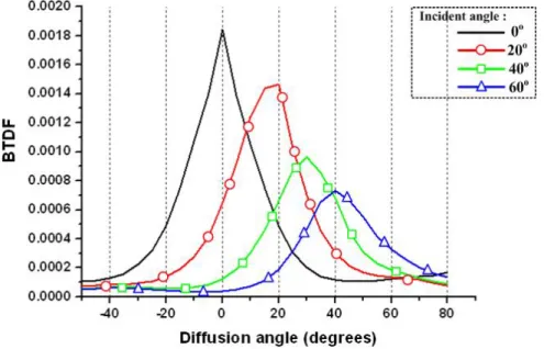
(23) 2.4 Bidirectional Reflection and Transmission Distribution Function. Bidirectional Reflection and Transmission Distribution Function (BRDF and BTDF), which are representations for light distribution, describe how much light is reflected and transmitted when light makes contact with a certain material. As shown in Fig. 12, BRDF taken for example is a function of light incoming direction and outgoing direction of viewer relative to a local orientation at the light interaction point. BRDF is defined as follows:. BRDF =. Aspot L0 P0 P0 R 2 = = , Ei A cos θ A Pi Pi A cos θ spot R2. (10). where L0 is the radiance and Ei is the irradiance of the spot area. Pi is the source power and P0 is the detected power. Simply speaking, BRDF and BTDF are the distributions in the hemi-spherical space when light is incident on the material with several different incident angles. Fig. 13 indicates BTDF of conventional diffuser passed through by the propagating light with incident angle of 0°, 20°, 40° and 60°. In general, BRDF and BTDF are adopted to describe the scattering phenomenon. BRDF and BTDF are assumed to be position-invariant, which means that whatever positions the propagating light is incident on, BTDFs are the same.. 12.
(24) Fig. 12 The definition of BRDF. Fig. 13 BTDF of conventional diffuser. 13.
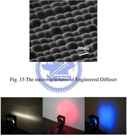
(25) Chapter 3 Beam Shaping Diffuser 3.1 Beam shaping Film with Lens Array. Beam shaping means that the propagating light is redistributed to form a specified shape in the spatial domain, such as the rectangular, circular and square shapes of light distributions. Beam shaping film, which is a transmissive component, designed for some special illumination purposes enable the efficient use of light by controlling light propagation and directing it to form a specified shape in the designated regions of space, as shown in Fig. 14.. Fig. 14 Beam shaping film which controls light propagation and directing it to form a specified shape. Engineered DiffuserTM developed by RPC Photonics is a typical example to shape the spatial distribution [6, 7]. Engineered Diffuser is based on the refractive micro-structures, as shown in Fig. 15. The micro-lens elements are arranged with. 14.
(26) 100% fill factor. Unlike conventional random diffusers such as bead-coating and micro-structure embossing diffusers, Engineered Diffuser can diffuse the propagating light into any specified shape in the far-field. Fig. 16 shows the beam shaping patterns controlled by Engineered DiffusersTM with different micro-structures. In this chapter, we adopt the characteristics of beam shaping film with lens array resulting in the square beam shaping patterns to apply to the scanning backlight module.. Fig. 15 The micro-structures of Engineered Diffuser. Fig. 16 Examples of LED light control with Engineered Diffusers. 15.
(27) 3.2 Scanning Backlight Module. Owing to the limitation of response time of liquid crystal, the motion blur is an issue in LCD. When watching the moving object, we can see the residue image behind the object like a tail, as shown in Fig. 17. In order to reduce the phenomenon, a method that a black frame is inserted between two frames can be chosen. Inserting black frame, however, sacrifices a mount of brightness as a result the contrast decreases. Furthermore, the scanning backlight is adopted to solve this problem [8]. As shown in Fig. 18, the backlight contains several rectangular light guides, which illuminate from top to under of the panel sequentially depending on the signal scanning way of the panel. In the ideal situation, each light guide performs high uniformity and efficiency and dose not influence each other. Fig. 19 shows the wedge type tandem light guides for large size panel [9]. Base on the technique of the scanning BLM, the researches, field sequential color LCD and high-dynamic-range (HDR) display, further develop to promote the image quality [10~12].. Fig. 17 Motion blur of a car moving. 16.
(28) Fig. 18 The scanning way of the divided light guides. Fig. 19 The divided wedge light guide designed for large size panel. We proposed a film, beam shaping diffuser, whose structure is spherical micro-lens array, to produce the square beam shaping pattern applied to the division areas in the scanning BLM. Fig. 20 illustrates the direct type scanning BLM in the ideal situation, in which the collimated light source illuminates and then the propagating light passes through the beam shaping diffuser to result in the division areas. This direct type BLM only composed of beam shaping diffuser and LED light source reduces some traditional devices such as light guide, BEFs and diffusers. It is expected that the system we proposed can have the uniformity approaching 90% and the tolerance of incident divergent light source.. 17.
(29) Fig. 20 Direct type scanning backlight module with beam shaping diffuser. 3.3 Simulations. 3.3.1 One-sided Lens Array The shape of the beam shaping pattern primarily depends on the shape of the micro-structures on the film. In Fig. 21, the beam shaping patterns in the far field of the different beam shaping diffusers which the collimated light passes through were demonstrated. The relief structures of the periodic micro-lens array are arranged on the film surfaces, on which each lens surface is spherical and the lenses have different shapes. Fig. 21 shows the examples of (a) square, (b) triangular and (c) hexagonal lens shapes. According to these patterns in the far field, which are the same as those of the lens structures, we know the fact that the shape of the beam shaping pattern is resulted from the shape of each element. The structures of beam shaping diffuser we adopted are the square lens array. The far-field diffraction pattern was simulated by a square lens array subject to different sags.. 18.
(30) Fig. 21 The periodic lens array which are (a) square, (b) triangular and (c) hexagonal result in the beam shaping patterns (d), (e) and (f), respectively.. In the following simulations, we chose the spherical lens sculptured into a square shape [Fig. 22(b)] while the square periodic lens is arranged as Fig. 21(a). The pitch p is fixed at 100um. The light source emits collimated light with circular shape with diameter of 0.5mm. Fig. 23 shows the patterns of beam shaping diffusers with different sags, which are observed on the plane located at one focal distance (f) and 100f. The patterns of the sags of 10um and 20um are square at 100f because the shape of the lens is square. However, the distortion of the square patterns is observed obviously while the sag is 30 and 40um. The reason is that spherical aberration occurs.. Fig. 22(a) The spherical surface lens (b) The lens sculptured into square shape 19.
(31) Fig. 23 The bean shaping patterns of the lens array diffusers with different sags observed on the plane located at focal distance of f and 100f. Fig. 24 Spherical aberration. Spherical aberration can be defined as the variation of focus. Fig. 24 is a somewhat exaggerated sketch of a simple lens forming an image of an object at a great distance away. The rays close to the optical axis come to the focus point which is very near the paraxial focus position. As the ray height at the lens increases, the position of the ray intersection with the optical axis moves farther and farther from the paraxial focus. Therefore, the larger the lens is, the more incident light deviates. As a result, the beam shaping patterns are not square and have distortion on the edge of the square shape. Additionally, the patterns at the focal point also explain spherical 20.
(32) aberration. The more obviously spherical aberration is shown, the larger light spot is. Furthermore, we observe the uniformity and the profiles of the beam shaping patterns as the increase of the numbers of lens, as shown in Fig. 25. The sag of each lens is fixed at 10um, and the pitch is 100um. The light source emits collimated light, and the observed plane is located at 100f. As the numbers of lens increase, the higher uniformity can be obtained, and the hot spot in the center of the beam shaping pattern is more indistinct.. Fig. 25 The uniformities and the profiles of the beam shaping patterns of the diffusers with different numbers of lens. 3.3.2 Both-sided Lens Array Beam shaping diffuser with both-sided lens array shown as Fig. 26(b) is able to increase the tolerance of the imperfect collimated light which is assumed to emit with a divergent angle. The beam shaping diffusers with one-sided lens array mentioned above have low tolerance of the imperfect collimated light, and the beam shaping 21.
(33) pattern is never formed as square shape, as shown in Fig. 27. In order to determine a square shape, square shape ratio is defined as blow:. square shape ratio =. AP , AS. (11). where AP is the area of the beam shaping pattern, in which the boundary is the full width at half maximum (FWHM). And AS is the area of the perfect square shape. Both of the length, lP and lS , must be equal.. Fig. 26(a) One-sided lens array (b) both-sided lens array. Fig. 27 Imperfect beam shaping pattern 22.
(34) The beam shaping patterns in Fig. 28 indicate the comparison between the perfect and imperfect collimated light passing through the one-sided square lens array film. The diameter of the light source is 2mm. The distance between the beam shaping diffuser and the light source is 0mm. The lens size is 100um, and the sag is 20um. The observed plane is located at 100f. In Fig. 28(c), the pattern with square shape ratio of 79% obviously is not controlled by the beam shaping diffuser. Therefore, the one-sided lens array film has low tolerance with incident divergent angle.. Fig. 28 The patterns resulting from the perfect and imperfect collimated light which passes through the one-sided square lens array film. In order to solve this problem, we proposed a method referring to the configuration in projector [13]. The flat plane on the opposite of the film is replaced with lens array in this case. Such two-sided lens array film is able to improve the drawback of low tolerance of one-sided film. The lenses on the two opposite lens array must coincide, and the distance between them is the focal length, f = 355um. Fig. 29 illustrates the lens array pair is able to redirect the incident light with an inclined 23.
(35) angle 10° shown as the red rays. The deviating light can be redirect to the area in which the perfect collimated light (white rays) produces the beam shaping pattern. The beam shaping patterns in Fig. 30 indicate the comparison between the perfect and imperfect collimated light passing through the two-sided square lens array film. The difference of the square shape ratios is small than 1%. Consequently, the beam shaping diffuser arranged by two-sided lens array has better tolerance with incidence subject to one-sided lens array.. Fig. 29 The opposite lens correcting the red light with an inclined angle. Fig. 30 The patterns resulting from the perfect and imperfect collimated light which passes through the one-sided square lens array film 24.
(36) 3.3.3 Applying to the Backlight Module Both-sided beam shaping diffuser is able to be adopted for the divided areas in the scanning BLM. The material of the film is PMMA, and the substrate thickness is 125um. We designed that the lens pitch is 100um and the sag is 24um. Then, two films are put together as a result the thickness of the film is the focal length of 250um, as shown in Fig. 31. The tolerance of light divergent angle of the diffuser we designed can be approaching 15°. Fig. 32 illustrates the direct type BLM within both-sided beam shaping diffuser. The distance between the detector and the both-sided micro-lens array diffuser is 120f, which is 30 mm. The light source close to the film illuminates imperfect collimated light with divergent angle 15° and the beam size is 10mm. One light source whose beam size is 10mm can produce a square beam shaping pattern whose length is 24mm. when combining 9 light sources, the length of the pattern is 54mm, as shown in Fig. 32(b), and we can get the uniformity achieved to 86%.. Fig. 31 Two one-sided lens array films put together. 25.
(37) Fig. 32(a) The profile of the direct type BLM (b) the beam shaping pattern (c) 9 LED light sources. 26.
(38) Chapter 4 High Gain Diffuser Film 4.1 Light Diffusion and Collection. Optical films are usually employed to promote light uniformity and collimation in the conventional backlight module (BLM). As shown in Fig. 33(a), after emitting from the light guide, light propagates through diffuser and is scattered into all directions of the hemi spherical space. Then the scattered light is redirected by two orthogonally arranged brightness enhancement films (BEFs) and collected to the normal direction. In order to reduce the production cost of the BLM, many novel devices were developed to reduce the usage of optical films or combine their functions [14~16]. In this chapter, a novel optical layout, high gain diffuser film with surface relief of lens array, performing dual functions of light collection and diffusion was proposed to combine BEFs and diffusers, as shown in Fig. 33(b).. Fig. 33(a) The conventional backlight module (b) lens array film replacing BEFs and diffuser in the BLM 27.
(39) 4.2 Film Structures. On the lens array film, the lens surfaces can be divided into five types, oblate ellipsoid, sphere, ellipsoid, paraboloid and hyperboloid, respectively. Any form of the aspheric or spherical surface can be described by aspheric equation, which is expressed as blow:. z ( x, y ) =. ( x 2 + y 2 )2 r 1 + 1 − (1 + c )(. ,. (12). x +y 2 ) r 2. 2. where c is the conic constant and r is the vertex radius of curvature. The surface type depends on the conic constants, as shown in the Table 2 and Fig. 34.. Table 2 Conic constants and surface types. c (conic constant). Surface type. (a). c>0. Oblate ellipsoid. (b). c=0. Sphere. (c). -1 < c < 0. Ellipsoid. (d). c = -1. Paraboloid. (e). c < -1. Hyperboloid. 28.
(40) Fig. 34 Surface types depending on conic constants in Table 1. Fig. 35 exhibits the hyperboloidal, paraboloidal and spherical surfaces, in which the length l is fixed and the vertex radius of curvature r decreases, where aspect ratio (AR) is defined as below:. h AR = . l. (13). Fig. 35 indicates that AR increases as r decreases. The prismatic structure of BEF can be regarded as a hyperboloidal surface shown as Fig. 35(a)(iii), where c = -2 and r is infinitesimal. In the other words, the feature shape is the asymptotes with slope angle of 45°. Therefore, the maximum AR of the hyperboloidal surface with c = -2 is 0.5. In Fig. 35(c), the spherical surface with c of 0 also has the maximum AR of 0.5, which is a hemi-spherical surface (r = l/2). However, the paraboloidal surface does not have the limit of AR because of its parallel asymptotes.. 29.
(41) Fig. 35 Examples of spherical and aspheric surfaces as r decreases. The lens shown as Fig. 36(a) is an aspheric lens model, where l is the length on the x-y plane and h is the height along the z axis. Aspect ratio (AR) was defined as the ratio of h to l. The lens surface is sculptured into a square shape to make 100% fill-factor on the substrate, as shown in Fig. 36(b), where p is the pitch of the square 30.
(42) lens. Fig. 37(a) is the schematic illustration of a lens array film periodically arranged with square shape. In order to reduce Moiré effect caused by the interference between its periodic structures and TFT array, the lens pitches are randomized as a result the lenses are not square as the periodic arranged one, as shown in Fig. 37(b).. Fig. 36(a) An aspheric surface lens (b) an aspheric surface lens sculptured into square shape. Fig. 37(a) The lens array film arranged by periodic square lens array (b) the lens array film subject to random lens pitches. 31.
(43) 4.3 Simulations. 4.3.1 Periodic Arrangement The optical function of a periodically-arranged lens array is primarily provided for light collection. The increase of the on-axis intensity along the normal direction is able to explain the light-collecting ability of a film. In general, BEF containing prismatic features is regarded as the best light-collecting component which enhances on-axis intensity achieved to 152%. And conventional diffuser not only scatters light into all directions but also offers about 123% on-axis intensity enhancement, as shown in Fig. 4. To compare the functions of the lens array film with BEF and diffuser, a backlight was modeled by the optical software, in which the light guide plate was assumed to emit light with Lambertian distribution. In the following angular intensity distribution figures, the x-axis is the viewing angle and the y-axis is the relative radiant intensity. The dotted line represents the Lambertian distribution light extracting from the light guide plate, in which the maximum intensity is normalized to be 1. In the following simulations, the lenses were classified by conic constants, and the parameter is aspect ratio (AR). A hyperboloidal lens model whose profiles shown as Fig. 38(a) is formed when conic constant c = -2, in which p = 100um and l = 100 2 um. Furthermore, the maximum AR is 0.5. Fig. 38(b) indicates the simulation results of hyperboloidal lens array films (HLAF) with c = -2. The “square symbol” represented by HLAF with AR of 0.5 has the highest relative intensity of 1.41 at viewing angle 0°. As the decrease of AR, the radiant intensity is lower.. 32.
(44) Fig. 38(a) The profiles of hyperboloidal surfaces (b) The angular intensity distributions of HLAF with different ARs. Fig. 39(a) The profiles of paraboloidal surfaces (b) The angular intensity distributions of PLAF with different ARs 33.
(45) A paraboloidal surface is formed when c = -1. Fig. 39(b) indicates the simulated performance of angular intensity distribution of paraboloidal lens array films (PLAF) with AR of 0.4, 0.6 and 0.8, whose profiles are shown in Fig. 39(a). The paraboloidal surface does not have the maximum value of AR. As the AR increases to exceed 0.6, the on-axis intensity does not increase. The “square symbol” represented by PLAF with AR of 0.6 has the highest relative intensity of 1.55 at viewing angle 0°. A spherical surface is formed when c = 0, whose profiles are shown in Fig. 40(a). The maximum value of AR is 0.5. Fig. 40(b) indicates the simulated performance of angular intensity distribution of spherical lens array films (SLAF). The “square symbol” represented by SLAF with AR of 0.5 has the highest relative intensity of 1.22 at viewing angle 0°. As the decrease of AR, the radiant intensity is lower.. Fig. 40(a) The profiles of spherical surfaces (b) The angular intensity distributions of SLAF with different ARs. 34.
(46) Fig. 41 The enhancements in the range of conic constants of -2.5~0.5 and the corresponding ARs. The conic constants of the examples mentioned above are -2, -1 and 0. Then, we will show the simulation results in the range of -2.5~0.5. In Fig. 41, the y-axis is the maximum enhancement of on-axis intensity and the corresponding AR. The x-axis is the conic constants. When conic constants are in the range of -1.4~-0.6 within AR of 0.5~0.7, these lens array films perform the high enhancement of about 1.55. Moreover, the paraboloidal surface located in the range is the applicable lens structure for light collection. Consequently, paraboloidal lens array film with periodic arrangement, which has better on-axis enhancement than conventional diffuser and single sheet of BEF, as shown in Fig. 42, is able to be regarded as a light-collecting component.. 35.
(47) Fig. 42 The angular intensity distributions of PLAF compared with conventional diffuser and BEF. 4.3.2 Random Arrangement Moiré effect in the conventional BLM is due to the interaction of the periodic structures of BEFs and the LCD pixels. In order to reduce Moiré effect, randomization of micro-features can alleviate such undesired characteristics [4]. Therefore, PLAF with periodic lens array is reformed as the random arrangement of the lens pitches. PLAF subject to random lens pitches was proposed as the high gain diffuser which diffuses and collimates light simultaneously. Considering the fabrication of PLAF, the vertex radius of curvature was fixed at 20um. According to the equation (1) and (2), the pitch of PLAF with AR of 0.6 is 68um. The smallest pitch of fabrication is 5um. The randomizing pitches are in the range of 5~68um within uniform distribution. Fig. 11 indicates light-collecting effects among conventional diffuser and PLAFs by the angular intensity distribution. Randomly-arranged PLAF perform 13.5% on-axis intensity decrease compared with 36.
(48) periodically-arranged PLAF but 9% increase compared with conventional diffuser. The random arrangement sacrifices the decrease of on-axis enhancement for the reduction of Moiré effect. Furthermore, the random range was not optimized.. Fig. 43 The angular intensity distributions of PLAFs and conventional diffuser. The diffusing ability can be explained by full width at half maximum (FWHM) of light diffusion in bidirectional transmittance distribution function (BTDF). Fig. 44 shows the BTDF of conventional bead-coating diffuser and PLAF subject to random lens pitches. At incident angle 0° shown by the “black solid lines”, FWHM of diffuser is 24° and randomly-arranged PLAF is 36°. In accordance with the comparison, the random arrangement has better diffusing ability than conventional diffuser. Additionally, BTDF explains the light-collecting ability. To take the “triangular symbol” of incident angle 60° for example, the output peak is located at 40° in BTDF of conventional diffuser. It means that the diffuser causes 20-degrees shift for 60-degrees incident light. However, randomly-arranged PLAF has 29° deviation. 37.
(49) Consequently, PLAF subject to random lens pitches possesses both of the light-collecting and diffusing abilities.. Fig. 44(a) BTDF of conventional diffuser and (b) randomly-arranged PLAF. 38.
(50) Transmittance is defined as the ratio of the energy passing through the film to the total energy of the light source. In the simulation model, a plane light source was assumed to emit light with Lambertian distribution, and no reflector is below it. Table 3 shows transmittance of PLAF and BEF. The transmittance of periodic PLAF is similar to single sheet of BEF.. Table 3 Transmittance of BEF and PLAF. Transmittance (%). Single sheet of BEF. Two sheets of BEFs. Periodic PLAF. Random PLAF. 52. 28. 51. 61. 39.
(51) Chapter 5 Conclusion Diffusing film is defined while the propagating light redistributes. A film is regarded as a diffusing film whatever functions it possesses when light passes through, such as light collection, diffusion or beam shaping. In general, the micro-structures of diffusing film control the propagating direction of light for specified distribution. In this study, two optical functions of the films with surface relief of lens array were proposed and applied to backlight module (BLM). Beam shaping diffuser with Both-sided lens array was adopted for the divided areas in the scanning BLM. We designed that the lens pitch is 100um and the sag is 24um. The thickness of the film is the focal length of 250um. The tolerance of divergent angle of the incident light is able to be approaching 15°. We got the uniformity achieved to 86%. The novel optical film, PLAF, was introduced to perform dual functions of diffusion and light collection. PLAF with periodic paraboloidal lens array enhances on-axis intensity achieved to 155% along the normal direction. On the other hand, PLAF subject to random lens pitches performs 134% on-axis intensity and 50% FWHM increase compared with conventional diffuser in BTDF. Therefore, randomly-arranged PLAF can be regarded as the high gain diffuser which is substituted for BEFs and diffusers in the BLM. In Appendix, the study “High Gain Diffusing Film with Surface Relief of 2D Paraboloidal Lens Array” was accepted and published in International Display Workshops (IDW) 2007, Sapporo, Japan.. 40.
(52) References [1] Masakazu Uekita, Yutaka Mineo, and Hitoshi Masaki, “A Novel Protective Diffuser for Backlit LCDs,” SID ’00 DIGEST, pp. 1036-1039, 2000. [2] Huang-Chen Guo, Cheng-Lin Yang, Ying Tsung Lu, Pong Lai, Wann-Diing Tyan, and Chang-Sheng Chu, “Novel Diffuser for LCD Backlight Application,” SID ’05 DIGEST, pp. 575-577, 2005. [3] R. C. Allen, L. W. Carlson, A. J. Ouderkirk, F. M. Weber, A. L. Kotz, T. J. Nevitt, C. A. Stover, and B. Majumdar, “Brightness Enhancement Film,” U.S. Patent No. 6111696, 2000. [4] Hwi Kim, Yong Jun Lim, Byungchoon Yang, Kyongsik Choi, and Byoungho Lee, “Geometrical Analysis of Optical Transmission Characteristics of Prism Sheet Layers,” Optical Engineering, Vol. 44(12), 128001, 2005. [5] Eugene G. Olczak, Masako Yamada, Dennis J. Coyle, and Daniel R. Olson, “A Moiré-Free Platform for LCD Backlighting,” SID’06 DIGEST, pp. 1336-1339, 2006. [6] Tasso R. M. Sales, “Structured Microlensarrays for Beam Shaping,” Optical Engineering, Vol. 42(11), pp. 3084-3085, 2003. [7] Tasso R. M. Sales, Stephen Chakmakjian, Donald J. Schertler, and G. Michael Morris, “LED illumination Control and Color Mixing with Engineered Diffusers™,” Proc. of SPIE, Vol. 5530, pp. 133-140, 2004. [8] A. A. S. Sluyterman and E. P. Boonekamp, “Architectural Choices in a Scanning Backlight for Large LCD TVs,” SID’05 DIGEST, pp. 996-999, 2005. [9] Yuan-Jung Yao, Yen-Hsing Lu and Chung-Hao Tien, “Tandem Light-Guide with Prismatic Micro-Bumps Structures for Field-Sequential-Color Backlight Module,” IDMC’07, pp. 409-412, 2007. [10] Kälil Käläntär, Tadashi Kishimoto, Kazuo Sekiya, Tetsuya Miyashita and Tatsuo Uchida, “Spatio-Temporal Scanning Backlight Mode for Field-Sequential-Color Optically Compensated-bend Liquid-Crystal Display,” Journal of the SID 14/2, pp. 151-159, 2006. [11] Ming-Chin Chien, Cho-Chih Chen, Yen-Hsing Lu and Chung-Hao Tien, “Region-Partitioned LED Backlight Design for Field Sequential Color LCD,” SID’07 DIGEST, pp. 441-444, 2007. [12] Yen-Hsing Lu, Yu-Kuo Cheng and Chung-Hao Tien, “A Localized Partition Approach for High-Dynamic-Range Display,” SID’07 DIGEST, pp. 449-452, 2007. [13] Koichi Akiyama, Matsumoto, “Light Device and Projector Equipped with the Same” U.S. Patent No. 7150535, 2006. [14] Liwei Lin, T.K. Shia, and Chun-Jung Chiu, “Fabrication and Characterization of 41.
(53) IC-Processed Brightness Enhancement Films,” IEEE, pp. 1427-1430, 1997. [15] A. Nagasawa, T. Eguchi, Y. Sanai, and K. Fujisawa, “A Novel Backlight System with the Unified Component,” IDW/AD’05, pp. 1285-1288, 2005. [16] Joo-Hyung Lee, Jun-Bo Yoon, Joon-Yong Choi, and Sang-Min Bae, “A Novel LCD Backlight Unit Using a Light-Guide Plate with High Fill-factor Microlens Array and a Conical Microlens Array Sheet,” SID’07 DIGEST, pp. 465-468, 2007.. 42.
(54) High Gain Diffuser Film with Surface Relief of 2D Paraboloidal Lens Array Shun-Ting Hsiao*, Po-Hung Yao** and Chung-Hao Tien* *Department of Photonics & Display Institute, National Chiao Tung University, Taiwan **Department of Photonics & Institute of Electro-Optical Engineering, National Chiao Tung University, Taiwan ABSTRACT A novel micro-structure diffuser film, paraboloidal lens array film (PLAF), was provided for the backlight module of liquid-crystal display (LCD). PLAF, which enables both of light-collecting and diffusing abilities, has the similar functions to BEFs and diffusers. PLAF with periodic paraboloidal lens array enhances on-axis intensity achieved to 155% along the normal direction. In addition, PLAF subject to random lens pitches performs 134% on-axis intensity and 50% full width at half maximum (FWHM) increase compared with conventional diffuser in bidirectional transmittance distribution function (BTDF).. z ( x, y ) =. ( x 2 + y 2 )2 r 1 + 1 − (1 + c)(. ,. (1). x2 + y 2 2 ) r. where c is the conic constant and r is the vertex radius of curvature. We are able to obtain the expression of the paraboloidal surface by setting c = -1. In addition, when c as 0 and -2, the spherical and prismatic surfaces are obtained, respectively, as show in Fig. 2. The vertex radius of curvature of the prismatic surface is infinitesimal.. 1. INTRODUCTION Optical films are usually employed to promote light uniformity and collimation in the backlight module (BLM). As shown in Fig. 1(a), after emitting from the light guide, light propagates through the diffuser film and is scattered into all directions within the hemi-spherical space. Then most scattered luminous is redirected by the light-collecting films toward the normal direction. In the conventional BLM, two orthogonally arranged brightness enhancement films (BEFs) containing prismatic features are treated as the light-collecting films to enhance the on-axis intensity along the normal direction [1, 2]. Besides, bead-coating and micro-structure embossing diffusers are generally applied in the BLM to increase the uniformity [3, 4]. In order to reduce the production cost, lots of studies were aimed to integrate various functions [5~7]. In this study, a novel optical layout, paraboloidal lens array film (PLAF), performing dual functions of diffusion and light collection is proposed to combine and replace BEFs and diffusers in the BLM, as shown in Fig. 1(b).. Fig. 1 Backlight modules of LCD (a) The conventional backlight module includes light guide, diffuser and light-collecting films (BEFs). (b) PLAF replaces the BEFs and diffuser in the BLM.. 2. FILM STRUCTURES A paraboloidal surface is one form of aspheric surfaces, and the mathematical expression of an aspheric surface is expressed as:. 43.
(55) The lens shown as Fig. 3(a) is a paraboloidal lens model, where l is the length on the x-y plane and h is the height along the z axis. Here the aspect ratio (AR) is defined as below:. AR =. h . l. Fig. 4(a) is the schematic model of PLAF arranged with periodic square lens array through the optical software. In order to reduce Moiré effect caused by periodic structures, the lens pitches are randomized as a result the lenses are not square as the periodic arranged one, as shown in Fig. 4(b).. (2). The paraboloidal surface is sculptured into a square shape to make 100% fill-factor on the substrate, as shown in Fig. 3(b), where p is the pitch of the square lens.. 3. SIMULATIONS 3.1 Periodic arrangement The optical function of PLAF with periodic lens array is primarily provided to collimate light. The increase of the on-axis intensity along the normal direction is able to explain the light-collecting ability of a film. In general, BEF containing prismatic features is regarded as the best light-collecting component which enhances on-axis intensity achieved to 152%. And conventional diffuser not only scatters light into all directions but also offers about 110% on-axis intensity enhancement. To compare the functions of PLAF with BEF and diffuser, a backlight was modeled by the optical software, in which the light guide plate was assumed to emit the lambertian distribution. In the following angular intensity distribution figures, the x-axis is the viewing angle and the y-axis is the relative radiant intensity. The dotted line represents the lambertian distribution light extracting from the light guide plate, in which the maximum intensity is normalized to be 1.. Fig. 2 Spherical and aspheric surfaces When conic constant c is 0, the surface is spherical. And when c is set as -1 and -2, the aspheric surfaces are paraboloidal and prismatic, respectively.. Fig. 3 Paraboloidal surfaces (a)The surface of the lens model is paraboloidal, and (b) the lens is sculptured into square shape.. Fig. 5 The angular intensity distributions of PLAFs with different ARs. Comparing PLAFs with AR = 0.4, 0.6 and 0.8, the “square symbol” represented by PLAF with AR of 0.6 has the highest relative on-axis intensity of 1.55.. Fig. 4 Paraboloidal lens array (a) PLAF is arranged with periodic square lens array and (b) subject to random lens pitches.. 44.
(56) Fig. 5 indicates the simulated performance of angular intensity distribution of PLAFs with different ARs. The “square symbol” represented by PLAF with AR of 0.6 has the highest relative intensity of 1.55 at viewing angle 0°. Considering the fabrication of PLAF, the vertex radius of curvature was fixed at 20um. According to the equation (1) and (2), the pitch of PLAF with AR of 0.6 is 68um. Fig. 6 shows the simulated performance of PLAF with AR of 0.6, hemi-spherical lens array film, BEF and conventional diffuser. In the simulations, BEF has grooves with prism angle fixed at 90° and the pitch of the grooves is 50um. The shape of the spherical lens is square like the arrangement of PLAF, and the pitch is 100um. As shown in Fig. 6, PLAF with AR of 0.6 has higher relative intensity of 1.55 than BEF slightly.. On the randomly-arranged film, the vertex radius of curvature was always fixed at 20um. The randomizing pitches are in the range of 5~68um. Fig. 7 indicates light-collecting effects among conventional diffuser and PLAFs by the angular intensity distribution. Randomly-arranged PLAF perform 13.5% on-axis intensity decrease compared with periodically-arranged PLAF but 22% increase compared with conventional diffuser. The diffusing ability can be explained by full width at half maximum (FWHM) of light diffusion in bidirectional transmittance distribution function (BTDF). Fig. 8 shows the BTDF of conventional bead-coating diffuser and PLAF subject to random lens pitches. At incident angle 0° shown by the “black solid lines”, FWHM of diffuser is 24° and randomly-arranged PLAF is 36°. In accordance with the comparison, the random arrangement has better diffusing ability than conventional diffuser. The fabrication is on the progress and the experimental results of PLAF applied to the BLM will be presented in the conference. Additionally, BTDF explains the light-collecting ability. To take the “triangular symbol” of incident angle 60° for example, the top value is located at diffusion angle 40° in BTDF of conventional diffuser. It means that the incident light at 60° shifts for 20° to extract. And randomly-arranged PLAF has 29° deviation. Consequently, PLAF subject to random lens pitches possesses both of the light-collecting and diffusing abilities.. Fig. 6 The angular intensity distributions of the films with different conic constants To compare PLAF with other films, the “square symbol” represented by PLAF, whose c is -1, has higher relative intensity of 1.55 than spherical lens array film, conventional diffuser and one sheet of BEF.. 3.2 Random arrangement Moiré effect in the conventional BLM is due to the interaction of the periodic structures of BEFs and the LCD pixels. In order to reduce Moiré effect, randomization of micro-features can alleviate such undesired characteristics [8]. Therefore, PLAF with periodic lens array is reformed as the random arrangement of the lens pitches. PLAF subject to random lens pitches we proposed is regarded as the high gain diffuser which diffuses and collimates light simultaneously.. Fig. 7 The angular intensity distributions of PLAFs and conventional diffuser Randomly-arranged PLAF perform 13.5% on-axis intensity decrease compared with periodically-arranged PLAF but 22% increase compared with conventional diffuser.. 45.
(57) ACKNOWLEDGEMENT This project was financially and technically supported by Industrial Technology Research Institute (ITRI), Taiwan, R.O.C. REFERENCES [1] R. C. Allen, L. W. Carlson, A. J. Ouderkirk, F. M. Weber, A. L. Kotz, T. J. Nevitt, C. A. Stover, and B. Majumdar, “Brightness Enhancement Film,” U.S. Patent No. 6111696, 2000. [2] Hwi Kim, Yong Jun Lim, Byungchoon Yang, Kyongsik Choi, and Byoungho Lee, “Geometrical Analysis of Optical Transmission Characteristics of Prism Sheet Layers,” Optical Engineering, Vol. 44(12), 128001, 2005. [3] Masakazu Uekita, Yutaka Mineo, and Hitoshi Masaki, “A Novel Protective Diffuser for Backlit LCDs,” SID ’00 DIGEST, pp. 1036-1039, 2000. [4] Huang-Chen Guo, Cheng-Lin Yang, Ying Tsung Lu, Pong Lai, Wann-Diing Tyan, and Chang-Sheng Chu, “Novel Diffuser for LCD Backlight Application,” SID ’05 DIGEST, pp. 575-577, 2005. [5] Liwei Lin, T.K. Shia, and Chun-Jung Chiu, “Fabrication and Characterization of IC-Processed Brightness Enhancement Films,” IEEE, pp. 1427-1430, 1997. [6] A. Nagasawa, T. Eguchi, Y. Sanai, and K. Fujisawa, “A Novel Backlight System with the Unified Component,” IDW/AD ’05, pp. 1285-1288, 2005. [7] Joo-Hyung Lee, Jun-Bo Yoon, Joon-Yong Choi, and Sang-Min Bae, “A Novel LCD Backlight Unit Using a Light-Guide Plate with High Fill-factor Microlens Array and a Conical Microlens Array Sheet,” SID ’07 DIGEST, pp. 465-468, 2007. [8] Eugene G. Olczak, Masako Yamada, Dennis J. Coyle, and Daniel R. Olson, “A Moiré-Free Platform for LCD Backlighting,” SID ’06 DIGEST, pp. 1336-1339, 2006.. Fig. 8 BTDF of conventional diffuser and randomly-arranged PLAF (a) The BTDF of conventional diffuser was measured by the collimated light with incident angle 0°, 20°, 40° and 60°. (b) The BTDF of PLAF subject to random lens pitches was simulated by optical software.. 4. CONCLUSION The novel optical film, PLAF, was introduced to perform dual functions of diffusion and light collection. PLAF with periodic paraboloidal lens array enhances on-axis intensity achieved to 155% along the normal direction. On the other hand, PLAF subject to random lens pitches performs 134% on-axis intensity and 50% FWHM increase compared with conventional diffuser in BTDF. Therefore, randomly-arranged PLAF can be regarded as the high gain diffuser which is substituted for BEFs and diffusers in the BLM.. 46.
(58)
數據

+7

相關文件
float voxelToPos(int p, int axis) const { return bounds pMin[axis]+p*Width[axis];. return
In addition, three seminars were held and in-depth interviews with 20 public-sector organizations and 20 individuals in the target sample population were
However, due to the multi-disciplinary nature of this subject, schools may consider assigning teachers with different expertise to teach this subject at different levels (S4, 5
Work in a collaborative manner with subject teachers to provide learners with additional opportunities to learn and use English in the school. Enhance teachers’ own
¾ A combination of results in five HKDSE subjects of Level 2 in New Senior Secondary (NSS) subjects, "Attained" in Applied Learning (ApL) subjects (subject to a maximum of
1.5 In addition, EMB organised a total of 58 forums and briefings (45 on COS and 13 on special education) to explain the proposals in detail and to collect feedback from
Learning elements of the knowledge contexts at junior secondary level in the TEKLA Curriculum Guide was enriched to give students a broad and balanced. foundation on
The connection between polar and Cartesian coordinates can be seen from Figure 5, in which the pole corresponds to the origin and the polar axis coincides with the positive
