Densification Improvement of Coarse Iron Powder for MIM Application 應用於金屬粉末射出成形之粗鐵粉之緻密化研究 殳國俊 黃坤祥 國立台灣大學材料科學與工程學研究所 NSC-92-2216-E-002-005 摘要 羰基鐵粉由於粉末細小,其平均粒徑約 5µm,燒結時可輕易緻密化,因此金屬粉末射出 成形(MIM)最常以此粉作為基礎粉。可是此細粉價格昂貴,使得 MIM 之應用不易有進一步的 發展。本實驗的主要目的為將粗鐵粉應用在MIM 中並且使其擁有高燒結密度。本實驗利用添 加α相穩定元素的方法,在基礎粉中分別添加 0.7wt%P、2wt%Si、5wt%Mo 和 6wt%W,於 1320
°C
下進行燒結後,量測試片燒結後的密度,並與同樣燒結條件下的羰基鐵粉做比較,目 的在評估添加α相穩定元素的可行性。實驗結果顯示:添加α相穩定元素後,試片密度從 80% 大幅提昇到95%。熱膨脹曲線顯示:添加 0.7% P 後的試片,由於在相變態前 P 已經充分擴散, 使得在燒結過程中試片會一直以α相存在。而 Mo、W 因為熔點高,在低溫下不易擴散,所以 α→γ之相變態現象依然存在,但在高溫時 Mo、W 會繼續擴散到鐵粉中使得組織從γ相轉變為 α相,然後繼續利用 BCC 鐵高的自擴散速率,其最後之燒結密度也會有明顯的改善。Fe-Si 合金由於在 1200℃時會形成液相,此也有助於提高燒結密度。整體看來,添加α相穩定元素 可以使粗鐵粉應用在MIM 製程中,進而降低生產成本,值得做進一步之研究。 關鍵字:金屬射出成形、粗鐵粉、固態燒結、緻密化、α相穩定元素 ABSTRACTCarbonyl iron powders are the most widely used raw powder in fabricating the powder injection molded (PIM) components owing to their high driving forces for sintering. However, the cost of this powder is relatively high. To improve the competitiveness of the PIM process, coarse iron powders, which are much more economical, were mixed with fine carbonyl iron powders in an optimum ratio of 6/4 in this study. This replacement of fine carbonyl iron powders did not change the kneading and molding behaviors significantly. The solvent and thermal debinding rates of the compacts that contain 100% and 40% fine powders also showed little difference. Such debinding results, which are contrary to the general belief, suggest that the particle size is not the critical factor in the debinding of PIM compacts. The debinding rate is more likely controlled by the diffusion of the soluble binder in the solvent (for solvent debinding) and the decomposition rate of the backbone binder (for thermal debinding).
High sintered densities can still be attained in the compact with mixed powders after α phase stabilizers, such as P and Mo, are added. These additives prevent the α-γ phase transformation and the accompanying exaggerated grain growth. When 0.7%P or 0.35%P+2.5%Mo is added into a mixed powder that contains 60% coarse iron powders, high densities more than 96% can be attained after the compact is sintered at 1320°C for 1hr. The hardness, tensile strength, and elongation of the Fe-2.5%Mo-0.35%P were HRB68, 520MPa, and 20%, respectively. The densities, mechanical properties, and comparable processing capability found in this study show that the more economical coarse iron powder can be used in the PIM process.
Keywords: powder injection molding, metal injection molding, coarse powder, densification, pore
1. Introduction
Due to the low solid content in the powder injection molded (PIM) compact, it is usually necessary to use powders with high driving forces for sintering in order to attain high final sintered densities. Carbonyl iron powders are, thus, the most widely used raw material in fabricating ferrous PIM
components, owing to the fine particle size. However, the cost of this powder is relatively high compared to that of coarse powders such as the water atomized or reduced iron powder used widely in pressed-and-sintered parts. Moreover, fine carbonyl iron powders produce small interparticle pores, which may hinder the solvent and thermal debinding and increase the total processing cycle time.1-3) To improve the competitiveness of the PIM process, as
compared to other manufacturing processes, the use of the more economical water atomized coarse iron powder is thus a favored
alternative.4-6) The trade-off, however, is the reduced sinterability due to the smaller surface area of the coarse powders and thus the lower final sintered density.
The first factor that causes the low sintered densities of iron powder compacts, other than the particle size effect, is the
exaggerated grain growth that accompanies the α-γ phase transformation at 912°C7, 8) The
second factor is the low diffusivity of iron when sintered above 912°C in the γ phase.9) To
inhibit exaggerated grain growth, Al, Ti, and SiO2 have been added to carbonyl iron
compacts to retard the grain boundary movement, and effective results have been reported.10-12) Another intuitive approach to alleviate this grain growth problem is to keep the sintering in the α phase and avoid the α-γ phase transformation. This can be achieved by sintering the compact below 912°C 13) or by
adding α phase stabilizers such as Mo, W, Si, and P.4, 5, 14, 15)
Various methods of using α phase stabilizers to improve the densification of mixed coarse and fine iron powder have been reported in the literature.4, 5) However, detailed processing information on the molding,
debinding, sintering, alloy homogenization, and mechanical properties are still limited. Furthermore, the modeling and experimental results focused on the effect of particle size on
debinding are even more limited. The objective of this study is thus to provide a detailed comparative study of the processing and properties of PIM compacts that are made from mixed coarse and fine powders.
2. Experimental Procedure
Two different types of iron powders were used in this study. The fine carbonyl powder had an average particle size of 4.25 µm, while the coarse water atomized powder had one of 45.7 µm. Table 1 shows the characteristics of these two powders. Two α phase stabilizers were evaluated as sintering aids. The Mo was introduced in the elemental powder form. The P was added in the form of Fe3P compound.
The characteristics of these two additives are also given in Table 1. The amount of each additive was calculated based on their binary phase diagrams with iron, so that, when completely homogenized, the compact would be in the α phase from 25°C to the sintering temperature of 1320°C.16) The amounts
selected were 0.7% and 5% for P and Mo, respectively.
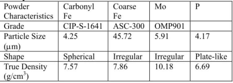
Table 1 The characteristics of the iron powders and α phase stabilizers used in this study.
Powder
Characteristics Carbonyl Fe Coarse Fe Mo P Grade CIP-S-1641 ASC-300 OMP901
Particle Size
(µm) 4.25 45.72 5.91 4.17
Shape Spherical Irregular Irregular Plate-like True Density
(g/cm3) 7.57 7.86 10.18 6.69 To prepare PIM specimens, a
multi-component wax-based binder was mixed with metal powders using a sigma-blade kneader. The amount of the solid powder was 93wt% or 63vol.%. The kneaded feedstock was molded into 2×10×100mm plates. The green strength of the specimens was measured using the four-point bending test. To evaluate the moldability, the length of the spiral flow in the mold was measured by following the ASTM D3123-72 method. Molded specimens were immersed in heptane to remove the soluble binder. The specimens were
subsequently heated at 5°C/min to 650°C and held for 1hr in hydrogen to thermally
distribution in the debound compact was analyzed with a mercury porosimeter. After debinding, specimens were heated at 10°C /min to 1320°C and sintered for 1hr. To monitor the sintering behavior, particularly during the phase transformation, dilatometry experiments were performed on the thermally debound specimens. The sintered density was measured by the Archimedes’ method. Results presented are the average of at least 5
specimens. 3. Results
3.1 Sintering Behavior
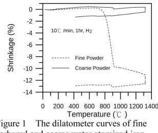
Figure 1 shows the dilatometer curves of the specimens made from 100% fine carbonyl iron powder and 100% coarse atomized powder, respectively. The trends of the curves were similar except that the amount of
shrinkage of the coarse powder was only 1.3 %, much smaller than the 12.9% of the fine iron powder. To increase the sintered density of the coarse iron powder, 0.7% P was added. But, the amount of shrinkage was still less than 9%. Thus, no further attempt was made using 100% coarse powders. Instead, mixed coarse and fine powders were used in the subsequent experiments.
Figure 1 The dilatometer curves of fine carbonyl and coarse water atomized iron powders heated at 10°C/min to 1320°C and then held for 1hr in hydrogen.
Since the packing density and the tap density of the coarse powder can be improved by filling their interstices with fine powders, the optimum ratio between the coarse and fine powder was evaluated. Figure 2 shows that the tap density of the mixed powder increased as the amount of fine powder increased. The
maximum density was attained at 40% fines and is similar to the calculated value of 33.4%.17, 18) This measured ratio of 40% was thus used for the preparation of the PIM specimens.
To examine how the feedstock of the mixed powder performed during PIM processing, its mold flow property was first examined by comparing the flow length in the spiral-flow mold to that of specimens made from 100% fine iron powders. Figure 3 illustrates that the flow lengths were almost the same for the two feedstocks. No
binder-powder separation, nor the rheological problem, which was the concern, was noticed during molding. The other concern was how easily the molded parts might be damaged during handling due to the replacement of the fines by the coarse powders. Table 2 shows that the green strength of the plate specimen made from the mixed powder is lower than that of the specimen made from the 100% fine powders. However, the difference is only 6.1%.
Figure 2 The measured and calculated tap densities of mixed iron powders with different ratios between the coarse and the fine.
Figure 3 The spiral lengths of molded specimens that were prepared from the 100% fine carbonyl powder and the mixed powder.
0 200 400 600 800 1000 1200 1400 Temperature (℃) -14 -12 -10 -8 -6 -4 -2 0 Sh ri n k ag e (% ) Fine Powder Coarse Powder 10℃/min, 1hr, H2 0 20 40 60 80 100
Percentage of Fine Powder (wt%)
3.5 4.0 4.5 5.0 5.5 6.0 Tap Den s ity (g/cm ) 3 measured calculated
Table 2 The bending strengths of the molded compacts that were prepared from fine and mixed iron powders.
Fine Powder Mixed Powder
Green Strength (MPa)* 14.7 13.8 Standard Deviation (MPa) 0.2 0.2 * average of 8 specimens
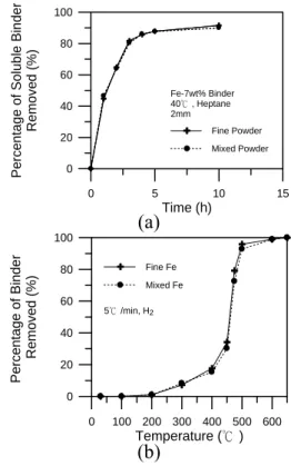
It is generally accepted that the solvent and thermal debinding rates are influenced by the pore size in the compact, which in turn are influenced by the particle size of the raw powder.1, 2, 3) To examine the effect of particle size on the solvent debinding behavior, the weight loss data were recorded after the specimens were immersed in heptane for different time. Figure 4(a) illustrates that the mixed powder had a similar solvent debinding rate as that of the fine powder. The thermal debinding rates of the two powders, as shown in Fig. 4(b), also demonstrate similar behavior. To analyze these results, the pore size
distributions of the debound compacts were measured. Figure 5(a) shows that the mixed powder produced only slightly larger pore size after solvent debinding. But, after thermal debinding, its pore size increased significantly. The pore size distribution also became much wider. The small difference in the average pore size, as shown in Fig. 5(a), suggested that most pores in the solvent debound compact were formed inside the binder due to the extraction of soluble binder components.19) They were not much related to the size of the interstices among iron particles.
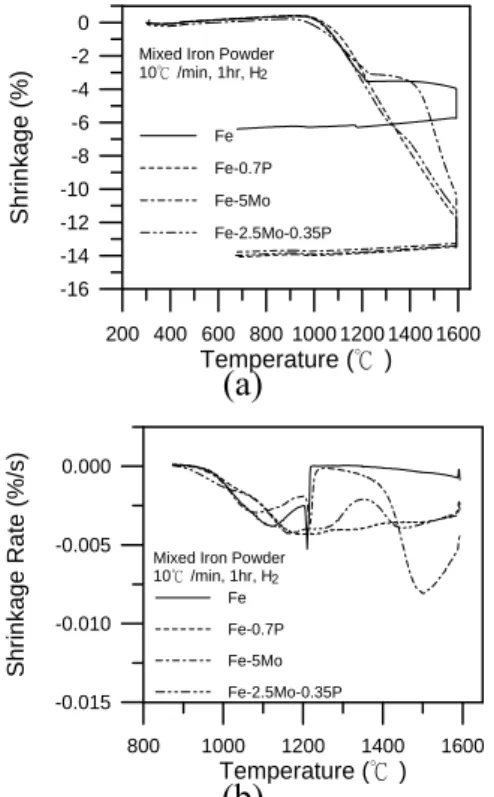
Figure 6 shows that the effect of Mo and P on the sintering behavior of mixed iron powders. With 5mass%Mo addition, the amount of shrinkage improved from 6.5% to 14%, and the sintered density increased from 82.5% to 97.8%. However, the phase
transformation was still noticeable at 912°C, indicating that the homogenization of Mo was incomplete. As expected, the shrinkage rate shown in Fig. 6(b) nearly ceased after the α-γ phase transformation. As the temperature further increased, the shrinkage rate increased again and reached a maximum at 1220°C. This suggested that the remaining Mo in the
compact had been further homogenized at high temperatures and that all the γ phase
(a)
(b)
Figure 4 The weight loss curves of molded specimens that were prepared from the 100% fine powder and the mixed powder during (a) solvent debinding and (b) thermal debinding.
(a)
(b)
Figure 5 The pore size distribution of (a) solvent-debound and (b) thermally debound compacts that were made from the 100% fine powder and the mixed powder.
0 5 10 15 Time (h) 0 20 40 60 80 100 Pe rc e n tage of Solubl e Bi nde r Remov e d ( % ) Fine Powder Mixed Powder Fe-7wt% Binder 40℃, Heptane 2mm 0 100 200 300 400 500 600 Temperature (℃) 0 20 40 60 80 100 Percentage o f Binder Removed (%) Fine Fe Mixed Fe 5℃/min, H2 0.1 1.0 10.0 100.0 Pore Diameter ( m) 0.00 0.01 0.02 0.03 0.04 0.05 C u mulative Volum e (m l/g) µ Fine Fe Mixed Fe S-D 40℃, heptane 0.1 1.0 10.0 100.0 Pore Diameter ( m) 0.00 0.02 0.04 0.06 0.08 Cumulati ve Volume (m l/g) µ T-D, 650℃ 5℃/min, 1hr, H Fine Fe Mixed Fe 2
(a)
(b)
Figure 6 (a) The dilatometer curves and (b) the shrinkage rates of Fe, Fe-5Mo, Fe-0.7P, and Fe-2.5Mo-0.35P specimens made from mixed iron powders.
transformed back to the α phase.
When 0.7%P, in the Fe3P form, was
introduced into the mixed iron powder, no discontinuity at 912°C was noticed. This indicated that the homogenization rate of the P was quite fast even in the compact that
contained coarse powders. The final density was 98.7%, relatively high, because there was no exaggerated grain growth and the whole sintering cycle was carried out in the α phase.
Although P is an effective sintering aid, it impairs the toughness and elongation of the sintered compact when a high amount is used. This drawback, however, can be alleviated by adding Mo, which retards the segregation of P to the grain boundaries.20, 21) Thus, the amount of P was reduced by 50% and 2.5% Mo, half of the quantity needed for Mo to keep iron in the α phase, was added. Figure 6(a) illustrates that the sintering behavior of the
Fe-2.5Mo-0.35P compact was very similar to that of the Fe-0.7P. The shrinkage rate curve in Fig. 6(b) shows that no significant phase transformation was noticed. When the compact was sintered at 1320°C for 1hr, the amount of shrinkage was 14%, and the final sintered density was 96.4%, also similar to those with
0.7%P or 5%Mo additions. 3.2 Mechanical Properties
The final sintered densities and hardnesses of the specimens that are made from mixed iron powders and α phase
stabilizers are summarized in Table 3. Despite the low carbon content of less than 0.03% in all specimens, a minimum hardness of HRB58 was attained. The densities were also greater than 96%. Further tests on Fe-0.35P-2.5Mo showed 520MPa tensile strength and 20% elongation. Since only ferrites are presented in the microstructure, these satisfactory
mechanical properties must be attributed to the high sintered density of 96% and the
solid-solution strengthening effect of the additives.
Table 3 The sintered densities and hardnesses of compacts that contain 60% coarse powder. Composition Sintered Density (%) Hardness (HRB) Fe 82.5 5.9 Fe-5Mo 97.8 58.3 Fe-0.7P 98.7 61.2 Fe-2.5Mo-0.35P 96.4 68.4 4. Discussion
4.1 Effect of Coarse Powder Addition on Debinding
In the case of the solvent debinding, several previous studies have proposed that the debinding rate is mainly controlled by the diffusion rate of the dissolved paraffin wax or other soluble binder components in the solvent and not particularly related to the pore or particle size.22, 23) However, in the case of thermal debinding, it is generally believed that the debinding rate of a PIM compact increases as the particle size increases. Such debinding can be further categorized into two modes. When the pore radius is smaller than the mean free path of the decomposed gas molecules, the flow of the gas is diffusion controlled. When the pore size is much larger than the mean free path of the gas molecules, then the flow of the gas is permeation controlled.1) With the large pore sizes present in the
compacts investigated, with most larger than 1
200 400 600 800 1000 1200 1400 1600 Temperature (℃) -16 -14 -12 -10 -8 -6 -4 -2 0 Shrin k ag e (% ) Fe Fe-0.7P Fe-5Mo Fe-2.5Mo-0.35P Mixed Iron Powder
10℃/min, 1hr, H2 800 1000 1200 1400 1600 Temperature (℃) -0.015 -0.010 -0.005 0.000 Shr in k age Ra te (%/s) Fe Fe-0.7P Fe-5Mo Fe-2.5Mo-0.35P Mixed Iron Powder
10℃/min, 1hr, H2
µm, the permeation mode should be the rate limiting mechanism. Numerous models have been proposed to approximate the debinding time or the permeability under such conditions. The most popular estimation suggests that the permeability is proportional to the particle size squared.24) However, the results in Fig. 4(b) indicate that the thermal debinding rate is not markedly related to the particle size.
These preliminary examinations suggest that the debinding of PIM compacts could be different from what is predicted by fluid flow through porous compacts. Our contradictory result suggests, instead, that debinding is controlled by the decomposition rate of the backbone polymer. Detailed studies with broader ranges of particle size, in both
diffusion and permeation controlled cases, and processing parameters will be necessary to further understand these findings and the interpretation.
4.2 Effect of α Phase Stabilizer on Densification
To fully take advantage of the elimination of the phase transformation of iron, the α phase stabilizers should be dissolved into the iron before the compact reaches912°C. Figure 6 indicates that only P was completely
homogenized, and thus no deflection on the dilatometer curve was noticed at 912°C. This is because P has a high diffusion rate in the iron, as shown in Table 4, and it was added in the form of fine compound Fe3P powders that
contained only 15.6% P. Thus, a greater volume of the additive was dispersed in the matrix, with the diffusion distance being thus decreased. In the case of Mo, it was added in the elemental powder form. Moreover, it has a high density. Thus, less volume of Mo was presented in the iron matrix and slower homogenization rates were expected.
It was also noticed in Fig. 6 that even when Mo was not completely homogenized and could not stop the phase transformation at 912°C, enhanced densification still occurred. This implies that either the exaggerated grain growth was retarded or that the diffusion rate was increased. An experiment was thus performed by heating the Fe-5Mo specimen made from mixed iron powders at 10°C/min to 930°C, immediately cooling it to 912°C, and
then holding it for 57mins. The results, as shown in Fig. 7, illustrates that considerable densification occurred during the isothermal sintering at 912°C. In contrast, the
densification of mixed iron powder stopped during holding. These results suggested that the un-dissolved Mo particles or Mo-rich areas will hinder the exaggerated grain growth of iron at 912°C and cause continued
densification.
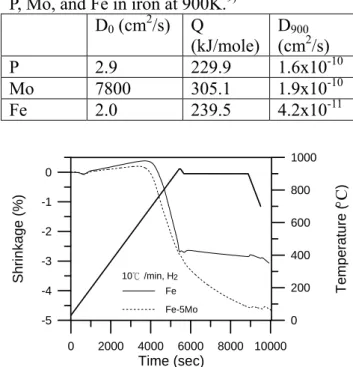
Table 4 The frequency factor (D0), activation
energy (Q), and diffusion coefficients (D900) of
P, Mo, and Fe in iron at 900K.9) D0 (cm2/s) Q
(kJ/mole) D(cm9002/s)
P 2.9 229.9 1.6x10⁻¹⁰
Mo 7800 305.1 1.9x10⁻¹⁰
Fe 2.0 239.5 4.2x10⁻¹¹
Figure 7 The dilatometer curves of Fe and Fe-5Mo specimens made from mixed iron powders when heated to 930°C, cooled immediately to 900°C, and then held for 57mins.
5. Conclusions
An attempt is made in this study to improve the competitiveness of the PIM process by replacing 60% of the fine carbonyl iron powder with the more economical water atomized powder. The kneading and molding behavior of the mixed powder, which has a high packing density, does not show significant differences from those of 100% carbonyl iron powders. The solvent and thermal debinding rates are also similar, contrary to general expectations. This irrelevance of the particle size in debinding suggests that the diffusion of soluble binders
0 2000 4000 6000 8000 10000 Time (sec) -5 -4 -3 -2 -1 0 Sh rin k age (%) 0 200 400 600 800 1000 Tem p e ratu re ( ) Fe Fe-5Mo 10℃/min, H2 °C
and the decomposition rates of the backbone binders are the controlling mechanisms in the solvent and thermal debinding processes, respectively.
To attain high sintered density of the mixed powder, α phase stabilizers, Mo and Fe3P powders, are introduced. The results
show that Fe3P is the most effective additive.
The elimination of the α-γ phase transformation and the accompanying exaggerated grain growth results in the final density of mixed powder compacts being improved from 82.5% to 98.7% for Fe-0.7P and 96.4% for Fe-0.35P-2.5Mo, respectively. The homogenization of the additives is satisfactory, despite of the large iron particles employed. The mechanical properties attained for the Fe-0.35P-2.5Mo are adequate for use as structural parts, as they have 520MPa tensile strength, 68HRB hardness, and 20%
elongation. References
1) R. M. German: Int. J. Powder Metall., 23 (1987) 237-245.
2) S. Krug, J. R. G. Evans and J. H. H. ter Maat: AIChE J., 48 (2002) 1533-1541. 3) R. N. Rickels: Chem. Eng., March (1965)
157-172.
4) G. J. Shu and K. S. Hwang: P/M Sci. Tech. Briefs, 5 (2003) 6-9.
5) L. W. Baum and M. Wright: U. S. Patent 5,993,507 (1999).
6) R. E. Wiech: U. S. Patent 4,602,953 (1986).
7) F. V. Lenel, G. S. Ansell and J. R. Strife: Modern Development in Powder Metall., MPIF, Princeton, NJ, 6 (1974) 275-292. 8) G. Cizeron and P. acombe: C. R. Acad.
Bulg. Sci., 1 (1955) 409-410.
9) Handbook of Chemistry and Physics, CRC Press, 61st ed., (1981) F-65.
10) Y. C. Lu and K. S. Hwang: Metall. Trans. A, 31A (2000) 1645-1652.
11) Y. C. Lu and K. S. Hwang: Powder Metall., 42 (1999) 257-262.
12) Y. C. Lu and K. S. Hwang: Chinese J. Mater. Sci., 31 (1999), 91-99.
13) Y. Kiyota: U. S. Patent 5,006,164 (1991) 14) K. S. Hwang and K. H. Lin: Powder
Metall., 35 (1992) 292-096.
15) P. D. Nurthen, M. C. Wells, P. Woods, D.
Thomson, and T. Abbott: Adv. Powder Metall. Part. Mater., ed. by A. Lawley and A. Swanson, MPIF, Princeton, NJ, 5 (1993) 215-227.
16) T. B. Massalski, J. L. Murray, L. H. Bennett and B. H. Baker: Binary alloy phase diagram, American Society for Metals, Metals Park, Ohio, (1986), 1080, 1090.
17) R. M. German: Acta Mater., 40 (1992) 2085-2089.
18) R. M. German and M. Bulger: Int. J. Powder Metall., 28 (1992)
301-311.
19) K. S. Hwang and Y. M. Hsieh: Metall. Trans. A, 27A (1996)
245-253.
20) C. Lindberg: Adv. Powder Metall. Part. Mater., ed. by J. M. Capus and R. M. German, MPIF, Princeton, NJ, 3 (1992) 99-106.
21) PH. Dumoulin and M. Guttmann: Mater. Sci. Eng., 42 (1980)
249-263.
22) S. T. Lin and R. M. German: Powder Metall. Int., 21 (1989) 19-24
23) I. Nanjo, M. Achikita, and S. Matsuda: Proc. 1993 Powder Metall. World
Congress, ed. by Y. Bando and K. Kosuge,
Part1 (1993) 241-244.
24) R. M. German: Powder Injection Molding, MPIF, Princeton, NJ, 1990, pp. 286-291.
APPENDIX
This appendix was accepted by Metallurgical and materials Transactions.
Solvent Debinding Behavior of PIM Components Prepared from Powders with Different Particle Sizes
K. S. Hwang, G. J. Shu, and H. C. Lee Department of Materials Science and Engineering
National Taiwan University Taipei, 106, Taiwan, R. O. C. ABSTRACT
It is generally accepted that the solvent debinding rate of powder injection molded (PIM) parts can be improved when coarse powder is used due to the larger pore size present in the compact. However, little hard experimental evidence on this has been reported. In this study, the as-received gas atomized stainless steel powder was classified into four different particle sizes. Little difference in the debinding rate was found among these four groups. Similar results were also obtained using classified fine carbonyl iron powder and coarse water atomized iron powders. The diameter of the pore channel that was developed in the compact, while increasing as the particle size increased for both iron and stainless steel powders, did not affect the debinding rate. A comparison between the sizes of the pores and diffusing molecules suggests that the pores are significantly large for the small diffusing molecules. The calculation of the diffusion path or torturosity also indicates that the particle size does not affect the diffusion length and thus not the debinding rate.
INTRODUCTION
Powder injection molding (PIM) is a widely used process in fabricating structural parts with complicated shapes. The general process begins with kneading metal or ceramic powders with multi-component binders. The kneaded feedstock is then molded into shapes and followed by debinding. One of the most widely used debinding processes is to immerse the molded part in a solvent bath to remove the soluble binders first. The solvent-debound parts are then heated to decompose the
remaining binder and subsequently sintered.[1] To understand the solvent rebinding behavior, Hwang et al. examined the
microstructure evolution of PIM compacts and the interaction between the binder components and the solvent during debinding.[2,3] It was shown that pore channels develop and the average pore size increases as the debinding proceeds. These pore channels provide paths for the dissolved solution to diffuse out of the compact. Since the diameters of these pore channels can be affected by the characteristics and the amount of the powder used, it is
possible that the debinding behavior will be influenced by the particle size. White and German showed that the debinding rate decreases when the powder loading increases due to the decreasing pore size between the particles in the compact.[4] Another work by Westcot et al. indicated that coarse stainless steel powders allowed a faster debinding rate than that of using fine iron powders.[5] It was postulated that feedstocks containing smaller powders have more interparticle contacts and smaller pores resulting in lower permeability. A recent study by Shu and Hwang, however, show that the mixed fine and coarse iron powder has a similar solvent debinding rate as did the fine iron powder.[6] But, no detailed experimental data on the characteristics of the pores or particles are given in these studies to explain these debinding results.
Several other studies investigated the debinding rate analytically and proposed that the solvent debinding rate is controlled by the interdiffusion of the solvent and the soluble binder.[7,8,9] Such a debinding behavior can be expressed by the following equation
-Ln(F) = Dp t π2/L2 --- (1)
where F is the fraction of the soluble binder remaining in the part; Dp is the diffusion
coefficient of the soluble binder, most
frequently the paraffin wax, in the solvent; L is the thickness of the part; and t is the debinding time. However, unlike the mechanisms
discussed in previous thermal debinding studies,[10-14] which postulate that the debinding rate of PIM products is influenced by the pore size in the compact, which in turn is influenced by the particle size of the raw powder, particle size is not included in this equation. Moreover, since solvent debinding is diffusion controlled, the diffusion length should be a critical factor. This implies that the tortuosity in the compact is also important. Since there are still unanswered questions and little experimental data have been reported in the literature, the objective of this study was thus to investigate in detail the particle size effect on the solvent debinding behavior of PIM products.
EXPERIMENTAL PROCEDURE
Stainless steel and iron powders are the two most widely used powders in the metal powder injection molding process and were thus selected in this study. In the first phase of the study, the gas atomized 316L stainless steel powder was chosen. Since this 316L powder was spherical, it eliminated the shape factor, which would have added to the complexity of the investigation. The characteristics and the morphology of the powder are shown in Table 1 and Figure 1a, respectively. The as-received powder was classified into four categories with an Alpine Zigzag Classifier (100MZR, Alpine Co., Augsberg, Germany). The classified powders were examined for their particle size distributions using a laser scattering analyzer (LS230, Coulter Co., Hialeah, Florida, USA).
To prepare the feedstock, the classified stainless steel powders were kneaded with 6wt% (35.5 vol%) binder, which consists of 40wt% polypropylene, 55wt% paraffin wax, and 5wt% stearic acid using a high shear rate mixer. The characteristics of these three binder components are given in Table II. Flat
rectangular specimens 10mm wide, 100mm long, and either 2 or 4 mm thick were molded from the feedstock using a 40-ton molding
machine (Arburg 270C, Arburg Gmbh, Lossburg, Germany). The barrel, nozzle, and mold temperatures employed were 155, 155, and 40 , respectively. For evaluation of the ℃ solvent debinding behavior, specimens were coated with epoxy resin on four sides, leaving only the top and bottom surfaces, 10mm by 100 mm, exposed to the ambient. To verify the effectiveness of the coating, the epoxy surface was examined after debinding. No cracks were found. A comparison of the debinding rate between the coated and non-coated specimens showed a difference of about 25% after the specimen was debound for 1 to 5 hours. This is very close to the 22%, which is the difference of the exposed area between the two
specimens. For debinding, the specimens were placed on stainless steel meshes with the side surface (2 or 4mm x 100mm) contacting the mesh. The size of the mesh opening was about 1mm. This allowed the top and bottom
surfaces to have a complete contact with the solvent. After the specimens were immersed in heptane at 50 for varying lengths of time to ℃ extract the soluble paraffin wax and stearic acid, they were removed from the solvent bath and vacuum dried at 25 for 3 hours before ℃ being measured to determine the weight loss. The debinding results presented are the average of four specimens. For evaluation of the pore structure evolutions, the pore sizes in the debound parts were analyzed using a mercury porosimeter (Autopore 9220, Micromeritics, Norcross, Georgia, USA).
In the second phase of the study, the range of the particle size was broadened. The powders selected were carbonyl iron powder, which is finer than the 316L powder, and water atomized iron powder, which is coarser than the 316L powder. The characteristics and the morphology of these two iron powders are shown in Table 1 and Figure 1. In the
preparation of coarse powder specimens, water atomized iron powder with an average particle size of 46.2µm was mixed with 6wt% binder, but without success due to its poor rheological behavior, which caused molding problems. Fine carbonyl iron powders were therefore added. Successful specimens were produced by mixing 40wt% carbonyl iron powder and 60wt% water atomized iron powder and using 7wt%(38.7vol%) binder. To facilitate the
comparison of the results of different iron powders, the amount of the binder used for the 100% fine carbonyl iron powder was also kept at 7wt%. The feedstock preparation, molding, debinding, and pore structure characterization procedures were the same as those for the stainless steel powder.
RESULTS
Powder Classification
In order to obtain sufficient powders for the experiments on each grade of the particle size, particularly the fines, 30 Kg of the as-received stainless steel powder was air classified. The average particle sizes of the four different grades were 6.25, 10.54, 15.53, and 21.12µm, respectively. The particle size distributions of these classified powders and the as-received powder are of the log-normal type, as shown by the straight lines in Figure 2a.
The carbonyl iron powder was also classified into two categories, coarse and fine, with average particle sizes of 2.34 and 6.14µm, respectively. Their particle size distributions are shown in Figure 2b. The classified coarse powder was of the log-normal type, but the fine powder was not and had a wide particle size distribution.
Solvent Debinding of Stainless Steel Powders Figure 3 shows the solvent debinding behavior of the 2mm thick specimens that were made from the as-received and classified stainless steel powders. In general, all the curves, which represent the weight loss of soluble binders, paraffin wax and stearic acid, are similar; only a slight difference was noticed between 2 and 8 ks. To further
understand the solvent debinding behavior, the pore structure evolution in the solvent debound specimen was analyzed. Figure 4 illustrates that the pore size increased as the debinding time increased in the specimen made with the 6.2µm 316L powder. Figure 5 shows similar debinding behavior in the specimen made with the 21.1µm powder. A comparison of Figure 4 and Figure 5 indicates that the fine powder produced a smaller average pore size than did the coarse powder.
Solvent Debinding of Iron Powders
In addition to the stainless steel powder, the weight losses in classified carbonyl iron
powders due to the removal of paraffin wax and stearic acid were also measured, as shown in Figure 6. Similar to the results for the stainless steel powder, the classified fine and coarse iron powders had comparable debinding rates. Another comparison of the debinding rate between the as-received carbonyl iron powder and the mixed powder, which consisted of 60% water atomized coarse powder and 40% fine carbonyl iron powder, was shown in Figure 7. The weight loss curves were also similar. For comparison of the differences in the pore structures, the pore size distributions of these two compacts, which were debound for 6 hours, were measured using a mercury porosimeter. Figure 8 illustrates that the mixed iron powder produced larger pore sizes after solvent debinding. These results of the pore size distributions, as shown in Figures 4, 5, and 8, and weight losses during debinding, as shown in Figures 3, 6, and 7, however, indicate that the particle size, though affecting the pore size, has little effect on the solvent debinding rate. A scanning electron microscope was thus also employed to examine more closely the morphology of the pore channels in the debound specimen. Figure 9 shows the pore structures in the 316L stainless steel, carbonyl iron, and mixed iron powder specimens of which 85% of the soluble binder had been removed. The figure demonstrates that the pore consists typically of small internal pores inside the polypropylene. Thus, the diffusion of soluble binder components, mostly paraffin wax, in the solvent during debinding should be related, if any, to the size of the pores inside the polypropylene.
DISCUSSION
Equation 1 indicates that the debinding time is inversely proportional to the thickness squared, or the diffusion length, to be more exact. This diffusion length can be influenced by the tortuosity, which could be related to the particle size, particle shape, and powder loading.[4] Since the 316L particles used in this study were spherical, the shape factor can be ignored. The effect of powder loading can also be disregarded because it was kept almost the same among the specimens. Therefore, the only remaining factor that can affect the tortuosity is the particle size. A calculation of
the diffusion length in the packing that was made from large and small spherical particles was thus performed. Figure 10 shows the simplified schematics of the 2-dimensional packing of coarse and fine spherical powders. Assuming that the diffusion of the soluble binder, mostly paraffin wax, is zigzagging along the path indicated, the total diffusion length, DL, from the center of the specimen to the surface can be calculated as follows.
DL = 2·n1·π·r1/3 = 2·n2·π·r2/3 --- (2)
where r1 and r2 are the radius of the
coarse and fine particles, respectively, and n1
and n2 are the number of coarse and fine
particles, respectively, as shown in Figure 10. Since 2n1r1 =2n2r2 =L/2, where L is half the
thickness of the specimen, the diffusion lengths obtained from equation 2 for coarse and fine powders are the same and are equal to π·L/6. This indicates that the critical factor that determines the debinding time is the
cross-section thickness. The particle size does not affect the torturosity for spherical powders, and thus not the debinding rate.
However, it was noticed during a
crosscheck of the debinding behavior in Figure 3, of the 6.2µm stainless steel, and in Figure 6, of the 6.1µm carbonyl iron powder that the debinding rate of the stainless steel powder is slightly slower even it has a similar particle size as the iron powder. This is understandable because the solid loading in the 316L
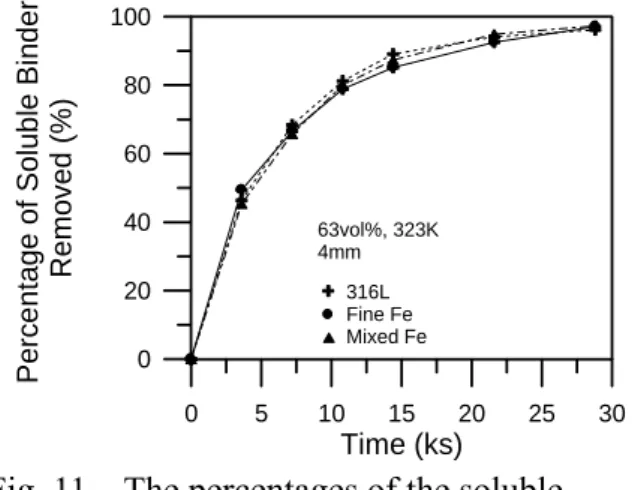
specimen is 64.5vol%, slightly higher than the 61.3vol% of the iron powder. With a higher solid loading, the debinding rate decreases because the total porosity and flux area for the soluble binder component to diffuse through decreases. For an accurate comparison, specimens with the same solid loading of 63vol% were prepared, and the thickness of the specimens was increased to 4mm to further facilitate the comparison. Figure 11 shows that the debinding rates of the as-received 316L, the as-received carbonyl iron powder, and the mixed iron powder are the same. This further confirms that the particle size has little effect on the debinding rate when the solid loading is kept the same.
It was also noticed in Figure 3 that smaller particles result in a faster debinding rate. But, Figure 6 indicates, though less pronounced, an opposite trend. It is possible
that the differences of debinding rates could be caused by the interaction between the powder and the binder during kneading. With different particle sizes and shapes, the homogeneity of the binder matrix in the feedstock and the specimen could vary. This may result in different pore characteristics within the polypropylene during debinding and thus affect the debinding rate. This postulation, however, needs detailed examinations to confirm. Furthermore, the largest ratio of the debinding rate between large and small particles is about 1.15 (15% higher for fine powders) at the debinding time of 3,600 seconds. This is relatively small compared to the large particle size ratio, 21.1µm/6.2µm=3.4. Thus, the difference of 15% was considered as not significant.
Although it is generally accepted that the debinding rate is influenced by the pore size, this study shows that larger pores do not enhance solvent debinding rate. This suggests that the pore size is still relatively large compared to the diffusing molecules even in fine powder specimens. Taking the 6.2µm 316L powder as an example, the average pore size after 10 minute debinding is about 250nm, as shown in Figure 4. This pore size, which was measured when all solvent in the pores was evaporated, was larger than the true size during debinding because the non-soluble backbone polymer swelled in the solvent and clogged the pore. However, the amount of swelling is usually less than 2%. Thus, the polymer swelling should not decrease the pore size significantly. [3, 5,15,16,17] On the other hand, the estimated root-mean-square length of the major soluble binder component, paraffin wax, which is a long hydrocarbon chain with about 25 carbon atoms is about 1.09nm.[18] Since the size of the paraffin wax is much smaller than the pore size, the diffusion rate of the paraffin wax should not be affected
significantly by the powder used in this study. This, however, does not mean that the
extremely fine powders, such as the
sub-micron powder, will also have the same debinding rate as micron-sized powders. This is because the pore size in the sub-micron powder specimens will be close to the size of the diffusing molecules. With the same reason, the debinding rate of a soluble binder, which
has a large molecular weight, may decrease the debinding rate. This means that there may exist a critical polymer size or pore size at which the particle size will have an effect on the debinding rate. But, a separate detailed study that uses much finer particles or larger molecular weight binders will be necessary before a universal conclusion can be drawn.
To further confirm that the pore size is not a critical factor either, the debinding rates of 6.2 and 21.1µm 316L stainless steel
powders were plotted as a function of the pore size of D90. As shown in Figure 12, there is
little correlation between the pore size and the debinding rate. The result supports the
postulation that when the pores are relatively large compared to the size of the soluble binder, the particle or pore size has little influence on the debinding rate.
Regarding the shape effect on the debinding rate, Figure 1 shows that the 316L powder is spherical. The carbonyl iron powder is also spherical, but with more satellites on powder surfaces. The water atomized iron powder is irregular. Despite the differences in morphology among the three powders, Figure 11 shows that the debinding behavior of the 316L, carbonyl iron, and the mixed iron powder, which contains 60% coarse irregular iron powder, are very similar. This suggests that for the three powders used in this study, their powder shapes, which are typical of the powder used in the industry, were not a critical factor in the debinding rate, either. Again, this does not mean that parts using powders with very irregular shapes, such as flaky powders, will also have the same debinding rate as the spherical powder. Detailed studies with a broader range of particle shapes will be necessary to further understand these findings and the interpretation thereof.
CONCLUSIONS
This study compares the solvent debinding rates of PIM compacts prepared from classified small and large spherical powders. The weight losses of the molded stainless steel specimens during solvent debinding show that particle size has little effect, despite the presence of larger pore channels in the coarse powder specimens.
Similar results are also found for classified iron powders. The comparison on the pore size and the size of the paraffin wax suggests that the pores are too large to affect the diffusion of the paraffin wax. The calculation on the
torturosity also suggests that it is not
significantly affected by the particle size when spherical powders are used. The main
parameter that determines the debinding rate is the compact thickness or the length of the diffusion path, which is influenced by the packing density. The results also show that the differences in morphology among the three powders examined are not significant enough to cause noticeable differences in the
debinding rate.
ACKNOWLEDGEMENTS
The authors thank the National Science Council of the Republic of China for their support of this work under Contract No. NSC-92-2216-E-002-005.
REFERENCES
1. R. M. German and A. Bose: Injection Molding of Metals and Ceramics, MPIF, Princeton NJ, 1997.
2. K.S. Hwang and Y.M. Hsieh: Metall. Trans.
A, 1996, vol.27A, pp.245-53.
3. H. K. Lin and K.S. Hwang: Acta Mater., 1998, vol.46, pp.4303-09.
4. G. R. White and R. M. German: Adv.
Powder Metall. Part. Mater., eds. A.
Lawley and A. Swanson, MPIF, Princeton, NJ, 1993, vol. 5, pp. 121-32.
5. E. J. Westcot, C. Binet, and R. M. German:
Powder Metallurgy, 2003, vol. 46, no. 1,
pp. 61-67.
6. G.. J. Shu and K. S. Hwang: Mater. Trans. JIM, submitted and revised.
7. S. T. Lin and R. M. German: Powder
Metall. Int., 1989, vol. 21, pp. 19-24.
8. D-S Tsai and W-W Chen: Ceramic Int., 1995, vol. 21, pp. 257-64.
9. I. Nanjo, M. Achikita, and S. Matsuda:
Proc. 1993 Powder Metall. World
Congress, Y. Bando and K. Kosuge, eds.,
1993, part 1, pp. 241-44.
10. R. M. German: Int. J. Powder Metall., 1987, vol. 23, pp. 237-45.
11. S. Krug, J. R. G. Evans, and J. H. H. ter Maat: AIChE J., 2002, vol. 48, pp.
1533-41.
12. B. A. Meyer and D. W. Smith: Ind. Eng.
Chem. Fund., 1985, vol. 24, pp. 360-68.
13. R. M. German: Powder Injection Molding, MPIF, Princeton, NJ, 1990, pp. 286-91. 14. S. Ergun: Chem. Eng. Prog., 1952, vol. 48,
pp. 89-94.
15. K.S. Hwang, H.K. Lin, and S.C. Lee:
Materials and Manufacturing Processes,
1997, vol.12, no.4, pp.593-608.
16. S.C. Hu and K.S. Hwang: Metallurgical
and Materials Trans. A, 2000, vol.31A,
pp.1473-78.
17. S. T. Lin and R. M. German: Powder
Metall. Int., 1989, vol. 21, pp. 19-24.
18. J. F. Shackelford: Introduction to Materials Science for Engineers, sixth ed., Pearson Prentice Hall, Upper Saddle River, NJ, 2005, pp. 471-75.
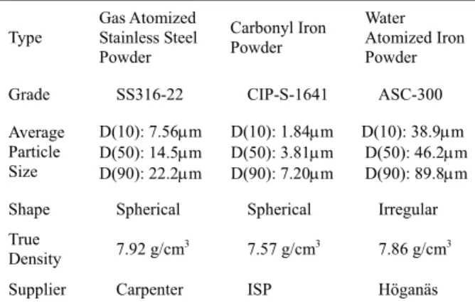
Table I The characteristics of the stainless steel powder and iron powder used in this study.
Type Gas Atomized Stainless Steel Powder Carbonyl Iron Powder Water Atomized Iron Powder
Grade SS316-22 CIP-S-1641 ASC-300
Average Particle Size D(10): 7.56µm D(50): 14.5µm D(90): 22.2µm D(10): 1.84µm D(50): 3.81µm D(90): 7.20µm D(10): 38.9µm D(50): 46.2µm D(90): 89.8µm Shape Spherical Spherical Irregular True
Density 7.92 g/cm3 7.57 g/cm3 7.86 g/cm3
Supplier Carpenter ISP Höganäs
Table II The characteristics of the polypropylene, paraffin wax, and stearic acid.
Binder Supplier Pycnometer density,
g/cm3 Point, ℃ Melting
Polypropylene Taiwan P.P.
Co.
0.903 169 Paraffin Wax Nippon Seiro
Co.
0.912 64 Stearic Acid Nacalai Tesque
Inc.
0.962 56
(a)
(b)
(c)
Fig. 1 The morphology of the as-received (a) gas atomized stainless steel powder, (b)
carbonyl iron powder, and (c) water atomized iron powder.
(a)
(b)
Fig. 2 The particle size distributions of the classified (a) stainless steel powders and (b) carbonyl iron powders.
Fig. 3 The percentage of the soluble binder in the stainless steel specimen that is removed during solvent debinding.
Fig. 4 The pore size change in the specimen that was prepared using the 6.2 µm fine stainless steel powder.
Fig. 5 The pore size change in the specimen that was prepared using the 21.1 µm coarse powder.
Fig. 6 The percentages of the soluble binders in the classified carbonyl iron powder
specimens that are removed during solvent debinding.
Fig. 7 The percentages of the soluble binders in the fine and mixed iron powder specimens that are removed during solvent debinding.
1 10 Particle Size ( m) -2 -1 0 1 2 Standard Deviatio n ( )σ µ
Gas Atomized Stainless Steel 316L As-received D = 14.5 m50 µ Classified D = 21.1 m50 µ D = 15.5 m50 µ D = 10.5 m50 µ D = 6.2 m50 µ 1.00 10.00 Particle Size ( m) -2 -1 0 1 2 S ta nda rd Deviat ion ( )σ
Carbonyl Iron Powder 1641 As-received Classified µ D = 3.8 m50 µ D = 6.1 m50 µ D = 2.3 m50 µ 0 2 4 6 8 10 12 Time (ks) 0 20 40 60 80 100 P e rce n ta ge of So lu bl e B ind er Re mo ved ( % ) 6.2 m 10.5 m 15.5 m 21.1 m As-received µ µ µ µ Solvent Debinding 316L, 323K 0 2 4 6 8 10 12 Time (ks) 0 20 40 60 80 100 P e rce n tage of Solub le Binder Removed (%) 6.1 m As-received 2.3 m µ µ Solvent Debinding Fe, 323K 0 2 4 6 8 10 12 Time (ks) 0 20 40 60 80 100 Perc e n tag e of So lub le B inde r Remo v e d ( % ) Solvent Debinding Fe, 323K Fine Fe Mixed Fe
Fig. 8 The pore size distributions in the fine and mixed iron powder specimens that were debound for 21.6ks.
(a)
(b)
(c)
Fig. 9 The pore structures of the debound specimens that are prepared from (a) as-received 316L powder, (b) as-received carbonyl iron powder, and (c) mixed iron powder.
Fig. 10 The schematics of the diffusion routes of the solution in the fine and coarse powder specimens.
Fig. 11 The percentages of the soluble binders in the stainless steel powder, carbonyl iron powder, and mixed iron powder
specimens that are removed during solvent debinding. 0.1 1.0 10.0 100.0 Pore Diameter ( m) 0.00 0.01 0.02 0.03 0.04 0.05 Cumulati ve Vo lume (m l/ g) µ Fine Fe (D =1.2 m) Mixed Fe (D = 2.4 m) Solvent Debinding 323K 50 50 µ µ 0 5 10 15 20 25 30 Time (ks) 0 20 40 60 80 100 P e rc e n tage of Solub le Bin d er Re moved (%) 63vol%, 323K 4mm 316L Fine Fe Mixed Fe