but propagation to its successors. In order to avoid error-cat-alyzed artifacts from producing visible corruption of affected video frames, the use of error concealment at the video decoder becomes essential. The purpose of this paper proposes an efficient and integrated novel EC method for the latest video compression standard H.264/AVC, using not only spatially and temporally correlated information but also the tandem utilization of two new coding tools: directional spatial prediction for intracoding and variable block size motion compensation of H.264/AVC. Exper-iments performed using the proposed hybridization method of combining the above spatial and temporal estimation elements ful-filled the expectations of control-whole-scheme. The experimental results show that the proposed method offers excellent gains of up to 10.62dB compared to that of the Joint Model (JM) decoder for a wide range of benchmark sequences without any considerable increase in time demand.
Index Terms—Error Concealment, H.264.
I. INTRODUCTION
T
HE JOINT Video Team (JVT), formed by the partnership of the ITU-T Video Coding Experts Group (VCEG) and ISO/IEC Motion Picture Expert Group (MPEG), has developed a new H.264/AVC video compression standard which achieves an improved compression efficiency of up to 50% over a wide range of bit rates and video resolutions when compared to previous standards [1]. H.264/AVC achieves highly efficient video compression by employing several new and powerful coding tools such as various directional spatial prediction for intracoding, adaptive motion compensation with variable block-sizes, multiple reference frames, quarter-sample accu-rate motion compensation, content-adaptive entropy coding, in-the-loop deblocking filtering, and so on [2].The H.264/ AVC directional spatial intraprediction exploits the spatial redundancy in the same frame and supports two intra 4 4 and intra 16 16 luma prediction modes. For the 4 4 luma block, there are eight directional and one DC (Mode 2) prediction modes estimated using the 13 boundary pixels (A to M) from previously coded blocks as indicated in Fig. 1(a). For the 16 16 luma block, there are three directional and one DC
Manuscript received August 31, 2007; revised March 31, 2008. First pub-lished July 27, 2008; last pubpub-lished August 20, 2008 (projected). This research was supported by the National Science Council, Taiwan under Grant NCS 95-2218-E-002-004.
The authors are with the Department of Electrical Engineering, National Taiwan University, Taipei 106, Taiwan.
Color versions of one or more of the figures in this paper are available online at http://ieeexplore.ieee.org.
Digital Object Identifier 10.1109/TBC.2008.2001150
tion modes with some modifications of DC (Mode 2).
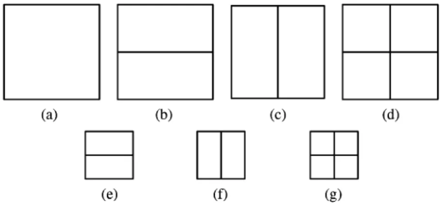
The variable block-size motion compensation using the temporal redundancy between successive frames supports seven inter modes of sizes 16 16, 16 8, 8 16, 8 8, 8 4, 4 8, and 4 4. The partition of each 16 16 macroblock can be left as a whole (16 16), or it can be divided into 16 8, 8 16, or 8 8 block modes. Each 8 8 sub-macroblock can, turn, be left as 8 8, or it can be further subdivided into 8 4, 4 8, or 4 4 sub-block modes, as shown in Fig. 2.
Highly compressed video bitstreams transmitted over error-prone communications networks can suffer from packet era-sures, especially in regard to wireless video transmission which can suffer packet loss more easily due to fluctuating channel conditions. This is especially true in situations such as the mul-ticast and broadcast of information in which the constraints on real time delay and jitter render retransmission a nonviable op-tion [3], [4].The use of error concealment at the video decoder becomes essential in order to recover the impaired video bit-stream, and also to prevent propagation of errors to the suc-ceeding inter-coded frames [3], [5].
Error concealment hides or recovers the errors in a recon-structed video at the decoder site by using temporal or spa-tial correlative information. Spaspa-tial error concealment (SEC) methods are based on spatial information in the recovery of a corrupted Macroblocks (MB), whereas temporal error con-cealment (TEC) methods are concerned with the estimation of missing motion vectors for motion compensated temporal re-placement of the impaired MBs. In this paper, we propose an integrated Hybrid Error Concealment method consisting of both
SEC and TEC techniques. In terms of SEC we propose two
SEC methods; one conceals the variances of the different kinds of damaged MBs targeted at any condition, and the other is speed-up which utilizes a H.264 coding tool, directional spa-tial intra prediction, in order to conceal the entire spectrum of damaged MBs targeted at intra-coded block(s). The proposed TEC techniques consist of a novel and unique mathematical model, the optimum regression plane, developed for the repair of damaged motion vectors, and the creation of a framework to perform the variable block size motion compensation based on predictive motion vectors in Laplacian distribution model space. We demonstrate that our integrated Hybrid Error Con-cealment (S/TEC) technique showed a significant increase of up to 10.62 dB at high packet error rates when compared to that of the Joint Model (JM) decoder, without significant gains in computational complexity.
Fig. 1. (a) Left: Illustration of nine 42 4 luma prediction modes. (b) Right: Illustration of four 16 2 16 luma prediction modes.
Fig. 2. Variable block sizes supported by H.264 for motion compensation. Top: macroblock partitions (162 16); Bottom: submacroblock partitions (8 2 8). (a) T1 (162 16); (b) T2 (16 2 8); (c) T3 (8 2 16); (d) T4 (8 2 8); (e) T5 (8 2 4); (f) T6 (4 2 8); (g) T7 (4 2 4).
The remainder of article is organized as follows. In Section II, a detailed review of relevant features of previous work is dis-cussed. Section III shows our innovative SEC, TEC, S/TEC methods by which to conceal the various sorts of impairment situations. Details of the simulation experiments and the results obtained are discussed in Section IV. Conclusions are drawn in Section V.
II. PREVIOUSWORK
Based on subjective viewpoint, we can divide EC schemes into either two or three categories depending on whether or not a combination method, S/TEC, is recognized as a respec-tive group. This paper exercises the three-group method, and below presents a detailed dissection of each of these important schemes.
A. Spatial Error Concealment
The Spatial Error Concealment (SEC) approach basically ex-ploits the spatial redundancy in a frame to conceal the missing
pixels without reference to other frames. One spatial conceal-ment method referred to in [6] recovers the lost pixels through weighted pixel value averaging, the weights being inversely pro-portional to the distance of source and destination pixels. This technique is usually most applicable in intra mode when re-placement is attempted without relying on additional informa-tion beyond the source-end. The reference software JM decoder implements both spatial and temporal EC for impaired MBs [7]; its SEC methods bear substantial similarity to those mentioned in [6]. Meisinger and Kaup present an approach that is distinct from most general SEC methods in that the estimated missing spatial information is in the frequency domain [8]. The approach of Wang et al. [9], [10] suggests hybrid methods that operate in the frequence domain by minimizing the spatial variation be-tween nearby samples within the damaged blocks and bebe-tween adjacent blocks using the principle of “maximally smooth re-covery” and thus restoring an optimally smooth transition across the block boundary [11]. Park et al. [12] and Hemani et al. [13] also make use of a method similar to Wang’s [9] in which they
logic reasoning [18], projection onto convex sets (POCS) [19], [20], maximum a posteriori (MAP) estimation procedure [21], best neighbor matching (BNM) [22], bilinear interpolation (BI) [6], [7], [23] and directional interpolation (DI) [19], [24]–[30]. Rongfu et al. [31] combine three methods: bilinear interpolation (BI), directional interpolation (DI), and best neighbor matching (BNM).
Agrafiotis et al. [32] provide a novel SEC model that involves the switching of BI and DI interpolation based on the entropy of the edge direction data in the neighborhood of each missing MB. This model employs directional entropy to characterize the features of the different video sequences, and exploits the advan-tages of both BI and DI approaches. The performance quality of concealing visual errors using the two approaches interchange-ably [32] creates a result that is superior to the singular use of BI and DI methods.
B. Temporal Error Concealment
The Temporal Error Concealment (TEC) approach exploits temporal redundancy in a sequence to recover the impaired MBs by utilizing reference frames. The most common mo-tion-compensated temporal prediction concealment approach combines both temporal replacement and motion compensa-tion by exploiting the generally strong correlacompensa-tion between correlative motion vectors in the current decoded frame and the previous one. In the case of a corrupted block exhibiting highly significant details such as a lost MB being unique to the frame, the temporal approach usually performs better than SEC, equaling a more successful restoration with the application of TEC. If the lost MB occurs in inter frame, an initial TEC ap-proach is advisable since related temporal motion information is available. Unfortunately, the motion vector of the damaged MB may also be lost because of the variable length coding employed. A number of varying simple approaches used in the estimation of the missing motion vector follow:
1) Using a zero motion vector involving the corrupted MB which is then replaced with one at the same spatial location within the previous frame.
2) Using the neighboring motion vectors (MVs) of the dam-aged MB.
3) Using the available MV of the spatially corresponding MB in the previous or forward frame [33].
4) Using the median (or average) of the spatially adjacent MVs [34].
5) Using conjunctively any of the set of the above candidate MVs [5], [32], [35]–[38].
developed a block-matching (BM) algorithm [16], called the forward–backward block-matching EC (F-B BM EC) method, to match the upper and/or lower adjacent MBs between current and reference frames in effort to conceal the damaged MBs of an MPEG-2 coded video sequence. In order to find the best match in the reference frame, the use of fast search algorithms is suggested [4], [16], [32], [36]–[38], [49]–[53]. More extensive research includes multiframe TEC approaches being reported in [54] and [55] at the detriment of increased complexity and time demand, as well as the concealment of whole missing frames as reported in [56] and [57].
C. Hybrid Error Concealment
The Hybrid Error Concealment (S/TEC) approach chooses an appropriate EC technique to recover the corrupted MBs, using either SEC or TEC approaches. For Tsekeridou and Pitas’s work involving MPEG-2, the S/TEC method [16] applied a SEC nique to the first Intra-frame of a scene and then a TEC tech-nique to the other frames in which is assumed a continuously high correlation between the frames of the entire sequence. In regard to the research of Wang et al. involving H.26L, the ref-erence JM software decoder applies SEC to intra-coded frames and TEC to inter-coded frames [7]. In analysis of more com-plex methods, one group [58], [59] employs a switching tech-nique based on measures of spatial and temporal activity in order to determine which concealment mode best suits the situ-ation. Another group [30], [60], [61] switches methods based on the intra or inter coding modes of the surrounding MBs of the Inter-frames. Yet another [32] adopts both of them. Of special interest, [62] and [63] combine both SEC and TEC algorithms to take both spatial and temporal correlation into account which are used conjunctively to exploit both the spatial smoothness and high temporal continuity, respectively. Another [64], makes use of a complex decision tree to differentiate the values of many alternate EC methods.
III. PROPOSEDMETHOD A. Spatial Error Concealment
Considerable research has been conducted in the field of EC in the hopes of ascertaining new spatial recovery methods. The first part of this section will focus on the introduction and dis-cussion of SEC methods.
1) Bilinear Interpolation: The BI spatial error concealment
algorithm uses the principle that each corrupted pixel can be replaced by linear interpolation using a weighted average of the nearest pixels existing along the one-pixel-wide boundary of the four adjacent MBs in both horizontal and vertical directions. The weights of the nearest four pixels on the boundary of the
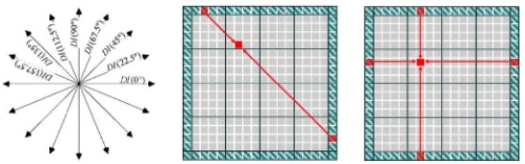
Fig. 3. Left: (a) The eight edge directions; (b) DI along a specific direction. Right: BI along the constant horizontal and vertical directions.
four adjacent MBs are inversely proportional to the distance of source and destination pixels.
The value of the missing pixel p(x,y) of BI is then interpolated by the formula:
(1) where the nearest vertical-horizontal pixels (p1, p2, p3, p4) and the corresponding distances (d1, d2, d3, d4) are shown on the right in Fig. 3.
A sample of BI approaches using spatial redundancy are dis-cussed in [6], [7], [23], and [31].
2) Directional Interpolation: DI consists of two main parts:
edge direction detection and 1-D interpolation. The initial step consists using of the edge direction filter to estimate the direc-tion of each pixel contained within MBs surrounding the lost MB. The most popular direction filter used by researchers is the Sobel Operator [65], but the Prewitt Operator is also frequently employed.
The 3 3 Sobel mask operators are as follows:
(2)
This is equivalent to the horizontal gradient Gx and vertical gradient Gy of pixel p(x,y).
The magnitude and direction of the gradient of pixel p(x,y) is calculated as:
(3) The edge direction is classified into 8 directions from 0 to 157.5 using a step of 22.5, as depicted in Fig. 3(a). The missing pixels are recovered by weighted 1-D interpolation along the strongest direction decided on the edge strength using border pixels of surrounding MBs, shown in Fig. 3(b).
The value of missing pixel p(x,y) of DI is interpolated by formula:
(4) where the decided pixels (p1, p2) and the corresponding dis-tances (d1, d2) are shown on the left in Fig. 3(b).
The related DI methods are reported in [19], [24]–[30].
3) Best Neighborhood Matching: Different from the above
interpolation methods, Wang et al. propose the BNM method which discerns block-wise similarity within the vicinity of the search range of the single frame in effort to recover the entire missing MB.
The detail BNM algorithm [22] can be divided into three steps:
1) Using the N-pixel-wide boundary surrounding the lost MB for use as a search-image.
2) Identifying the best-matched MB in the search vicinity. 3) Replacing the missing MB with the corresponding part of
the best-matched MB isolated in step (2).
Additional research in the area of the BNM algorithm is in [22], [31], and [53].
4) Discussion: So far, this paper has discussed three basic
SEC methods. Now we will summarize and analyze the main facets of and differences between BI, DI and BNM. Human visual perception is highly sensitive to distortion of edges in-cluding impairments on existing edges (blurring) and the cre-ation of false edges (blockiness) [66]. Additionally, according to psychovisual studies, an individual edge does not influence our perception but rather interacts with other neighboring edges to create a composite effect which we are then able to recog-nize [67]. Thus, since edges play such an important role in the human visual system, it is equally important that they are pro-tected from deterioration, and that false edges are safeguarded against.
DI exhibits many advantages in the area of edge protection. It can facilitate the preservation of the existing strong edges, as well as avoiding strong edge blur when the strong edges of the damaged MBs have only single directions, as illustrated in Fig. 4(b). Unfortunately, because DI is interpolated along a single direction it can result in the creation of false edges or the emphasis of relatively weak ones if there is more than one edge in the neighborhood, as illustrated in Fig. 4(d). On the other hand, the use of BI can help avoid the creation of false strong edges, as illustrated in Fig. 4(c). However, BI can blur original strong edges if only one edge exists in the neighborhood, as il-lustrated in Fig. 4(a). The damaged block replaced by interpola-tion will smoothly connect with its adjacent neighborhoods. But in areas of higher complexity, the spatial interpolation methods cannot completely describe missing or damaged blocks because the necessary reference blocks may simply not exist. BNM can recover damaged information in high detail, but may create edge discontinuity. It will also cause higher computation complexity than BI and DI when searching for a match and will thus be less time-efficient.
Proposed normal SEC mode: In recent years research
con-ducted in the area of SEC has been oriented towards a combi-nation method using several SEC techniques whose respective uses are determined according to image content and complexity. The most current findings, as of the publication of this paper,
Fig. 4. The damaged MBs concealed by BI and DI.
Fig. 5. Damaged MB with multiple edge directions.
were conducted by Agrafiotis et al. [32] and discuss a combina-tion method by which the switching of Bilinear (BI) and Direc-tional (DI) Interpolation proved extremely useful in the replace-ment of missing MBs. Although this method is very successful in many situations, there are instances when the image is too complex to be repaired entirely by this technique. This paper will now analyze the situations in which the method of Agrafi-otis et al. [32] is least effective and suggest a novel way in which its problems may be solved. For more complicated situations in which the surrounding MBs exhibit many different directions, vertical-horizontal interpolation (BI) or one directional interpo-lation (DI) are alone not sufficient to recover the real image. For example, Fig. 5 below illustrates a multidirectional nature.
Increasing recovered video quality is essential in the con-sideration of important factors in the above situation. With these issues in mind, we will employ a novel and enhanced DI method in order to accomplish multi-directional interpolation. Initially in normal SEC mode, we make use of the 3 3 Sobel edge direction filter to calculate gradient and magnitude of surrounding pixels which exist in the four-pixel-wide external boundary around the missing MB and thus correspond to one of eight different edge directions, as shown in Fig. 3(a).
Based on the calculated edge strength value, the strong edges are reserved as candidate edges which are then used in the cal-culation of the directional entropy (DE). Entropy describes the
state of disorder in a system [68]; in the attainment of directional distribution, entropy (DE) can be calculated by
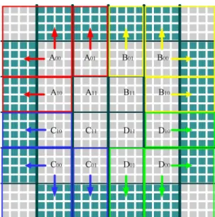
(5) where p(dx) is the directional probability density function asso-ciated with the candidate edge direction data (dx). Large DE in-dicates the existence of no specific edge direction, since edges of different directions interact with each other, whereas small DE indicates the existence of only one dominant edge direction in the area. The surrounding pixels within the four-pixel-wide external boundary are disjoined into 4 4-pixel blocks.
For each 4 4-pixel block a threshold between 0 and 0.85 indicates that the 4 4-pixel block possesses a clear dominant edge and can be marked as a candidate block. The formula for threshold is given by
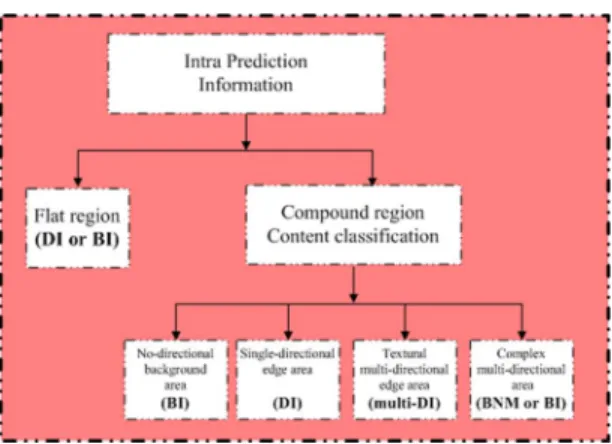
(6) A threshold equal to 1 corresponds to all directions being equally probable. When using the surrounding 4 4-pixel blocks to estimate the missing MB, the deficient content can be classified into one of the following four categories: no-direc-tional background area, single-direcno-direc-tional edge area, textural multi-directional edge area, and complex multi-directional edge area (Fig. 6) four categories as follows:
1) No-directional Background: The 4 4-pixel surrounding blocks completely lack strong edge directions. It allows reasonably good approximation of damaged MBs that exist as the background or panning region of an image. Each pixel of damaged MBs can be replaced by BI.
2) Single-directional Edge Area: Each 4 4-pixel sur-rounding candidate block exhibits the same singular strong edge direction. DI is the most useful method for this scenario, as it is most beneficial in the protection of strong edges and avoidance of the creation of false strong edges, as shown in Fig. 7(a).
3) Textural Multi-directional Edge Area: Each 4 4-pixel surrounding candidate block exhibits more than two strong
Fig. 6. Framework of Normal SEC method.
Fig. 7. (a) Example of DI. (b) Example of Multi-DI.
edge directions. The direction of each missing pixel is ap-proximated by the corresponding directional strong edge within the surrounding candidate blocks.
Three-directional weighted interpolation (multi-DI) of the one-pixel-wide border along the corresponding horizontal, vertical, and one and forty-five degree directions, is the most useful method in the identification of the directions of the missing pixel, and is illustrated in Fig. 7(b). If the missing pixels do not have a corresponding strong edge direction, the lost pixels can be interpolated along the same direction corresponding to that of the nearest missing pixel. The multi-DI approach seems very complex and thus time-consuming, but its time complexity is in fact very similar to single-directional DI.
4) Complex Multi-directional Edge Area: Each 4 4-pixel surrounding candidate block has more than two strong edge directions, with the direction of each missing pixel either corresponding to different strong edge directions within the candidate blocks or maintains a threshold of more than 0.85 for most surrounding blocks. If the damaged MB exhibits complex content, then BNM may be adopted in order to reconstruct the damaged block. The effectiveness of the BNM method in terms of recovery image quality is very useful for complex areas [22], [31], but the time requirement for the computation load is relatively high. Conversely, the BI method for complex areas [32] offers a diminished time constraint, however the quality of the result will usually be lower than that of BNM.
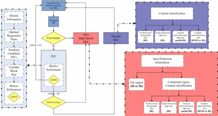
Proposed intra high-speed SEC mode: In terms of time
expenditures, the detection of edge direction of DI, of the switching method of DI and BI [32], and of normal SEC methods, takes 42%–86% of computation on average and is
Fig. 8. Framework of High-Speed SEC method.
obviously the processing bottleneck of these SEC methods. To reduce the complexity of edge direction detection, we shift the emphasis away from the role of damaged content classification to the role of edge direction detection. The initial event of note is that there is a correlation between intra-prediction modes and edge direction. With the exception of DC prediction mode, the coding modes of the eight directional 4 4 prediction modes and the three directional 16 16 prediction modes provide a strong estimation for the edge direction of the real images in H.264/AVC intra coding [69].
The intra prediction modes provide useful clues about edge direction that serve to reduce the initially large number of Sobel edge filter calculations. Then, it can reduce the complexity of the process of edge direction detection by 74%–96% on average. The mode information of intra 16 16 prediction mode tends to be chosen for background or flat regions and intra 4 4 pre-diction mode tends to be used for foreground or highly textured regions [69]. By utilizing the intra prediction mode information of the surrounding area, the initial step of the Intra High-Speed SEC method classifies each damaged MB into two categories: flat region and compound region (Fig. 8)
1) Flat region: For the six neighborhoods of each damaged MB (Top, Top-Right, Left, Right, Bottom, and Bottom-Left), there are at least five adjacent MBs chosen via 16 16 prediction mode. It does not need to use any Sobel filters in the detection of edge direction for the panning region of an image. Each pixel of damaged MBs can be interpolated along a single direction (vertical, horizontal or diagonal) or bidirection (vertical-horizontal) decided by majority de-cision based on the intra 16 16 prediction mode, mode 0 (vertical), mode 1 (horizontal), mode 3 (plane), and mode 2 (DC), of corresponding surrounding MBs.
2) Compound region: For the mixed 16 16 and 4 4 pre-diction modes of surrounding MBs, the four-pixel-wide boundary is disjoined into 4 4-pixel blocks, as shown towards the right in Fig. 9.In order to ascertain the exis-tence of the dominant edge of each 4 4-pixel block and mark it as a candidate, we use the intra mode information and a small amount of the edge direction filter. The order of calculation of the Sobel filter to estimate the direction and magnitude of the inner pixels, p1, p2, p3, and p4, is depicted on the left in Fig. 9. The calculation is stopped if the candidate block is decided upon. For each 4 4-pixel block, edge detection begins at the p1 and p2, at least one
Fig. 9. The order of calculation of Sobel Filter.
of them exhibiting an existing strong edge in the same di-rection as obtained by intra mode prediction and marked as a candidate block. If neither p1 nor p2 exhibit an existing strong edge, then two additional points, p3 and p4, will be calculated. Intra DC prediction mode is regarded directly as no singular prominent edge exists in the 4 4-pixel block without the need of any Sobel filters. The final part is similar to the normal SEC method; both classify the de-ficient content into four categories: no-directional back-ground area using BI method, single-directional edge area using DI method, textural multi-directional edge area using multi-DI method, and complex multi-directional edge area using BMN or BI method.
B. Temporal Error Concealment
In this section, we propose a mathematically optimized TEC approach for H.264/AVC decoders. The statistical analysis of the correlations between the set of motion information and the motion of the missing MB was conducted on an extensive random basis. Using spatial redundancy, the optimum regres-sion plane utilizes the spatial neighborhood MVs of the lost MB in order to estimate the sixteen MVs within each 4 4 block of the damaged MB. One of the spatial and temporal candidate MVs of each 4 4 block in the damaged MB that minimizes the boundary matching error is selected. The most suitable MB partition (including the sizes 16 16, 16 8, 8 16, and 8 8) is decided upon, according to the motion field distributions and correlations between the sixteen MVs of each 4 4 block within the damaged MB. At the end of this process, the winning MVs are subjected to variable block size motion refinement and motion-compensated temporal concealment, resulting in new MVs derived from a motion search carried out in the decoder. Fig. 10 illustrates the primary TEC method flowchart which is utilized in this paper, and which we will discuss in detail.
1) Motion Information: In order to estimate the motion
of the missing MB, there are four categories of crude mo-tion informamo-tion which must be taken into consideramo-tion: zero MV, spatially correlated neighboring MVs, temporally correlated MVs of the same spatial position, and temporally correlated neighboring MVs, as described in [5], [32]–[38]. In H.264/AVC, a 16 16 MB can be divided into 16 16, 16 8, 8 16, 8 8, 8 4, 4 8, and 4 4 block shapes for motion estimation. We first disjoin each block exhibiting different size into the smallest block-size (4 4) and conduct
Fig. 10. Framework of the proposed TEC method.
Fig. 11. The damaged block with neighboring blocks in the current frame (fore-ground) and the collated blocks in the reference frame (back(fore-ground).
experiments with which the motion vectors of the above four categories, as illustrated in Fig. 11, are statistically analyzed in effort to obtain the missing block with wide random selection (25%). We then test the result using eight 100-frame video sequences (“Carphone,” “Container,” “Foreman,” “Grandma,” “Mother and Daughter,” “News,” “Salesman,” “Stefan,” and “Silent”) in 4:2:0 format with QCIF (176 144), the results of which are shown in Table I. In Table I, the first eight rows represent the probabilities (P) where the motion vector of each 4 4 block is the same as its neighbors directly above (Top, Top-Left, Top-Right), adjacent (Left, Right), and below it (Bottom, Bottom-Left, Bottom-Right); P (8-Neighbors) denotes the probability where the motion vector of each 4
TABLE I
MOTIONVECTORCORRELATION OFCORRESPONDINGBLOCKS. P(X) DENOTES THEPROBABILITY
4 block is the same as at least one of its eight surrounding neighboring blocks; P (Zero) denotes the probability where the motion vector of each 4 4 block is zero; P (At least one zero) denotes the probability where the motion vector of each 4 4 block is zero and at least one of its eight surrounding is also zero; the following eight rows denote the probabilities where the motion vector of each 4 4 block is the same as its neigh-bors in the previous frame that are directly above (Collocated Top, Collocated Top-Left, Collocated Top-Right), adjacent (Collocated Left, Collocated Right), and below it (Collocated Bottom, Collocated Bottom-Left, Collocated Bottom-Right); P (Collocated) denotes the probability where the motion vector of each 4 4 block is the same as the one of the same spatial location in the previous frame; P (Collocated 9-Neighbors) denotes the probability where the motion vector of each 4 4 block is the same as at least one of its collocated neighboring blocks in the previous frame.
We can see that the correlation between the spatial MVs (Rows 1–9) is the highest on average while zero MV (Row 10) is lowest on average; when the missing MV is zero, there is a guarantee of, on average, 97-100% that at least one of the surrounding MVs is also zero, indicating that the surrounding MVs are sufficient to represent zero MV. Clearly, the findings indicate that when estimating the missing motion vector, we should take first into consideration the surrounding MVs,
the fact summary table of which (Table I) indicating that the surrounding MVs and collocated MVs have high possibility for candidacy.
2) Optimum Regression Plane: We make use of the
signif-icantly strong correlation between spatial MVs to estimate the missing motion vectors based on the optimum regression (OR) plane. For the approach proposed in H.264/AVC, we have as-sumed that the location of corrupted MBs has been accurately detected, and all the related surrounding MBs are correctly re-ceived and decoded due to the interleaving technique of flexible macroblock ordering (FMO) [70] that is used to avoid succes-sive lost MBs.
In the two-dimensional (2-D) real space current frame with each pixel size equaling one unit, we first set up the coordi-nates of the damaged MB with center at (0, 0), and the cor-responding coordinates of the surrounding 4 4 block cen-ters at the following: Block 1 : , Block 2
: , Block 3 : , Block 4 : , Block 5 : , Block 6 : , Block 7 : , Block 8 : , Block 9 : , Block 10 : , Block 11 : , Block 12 : , Block 13 : , Block 14 : , Block 15 :
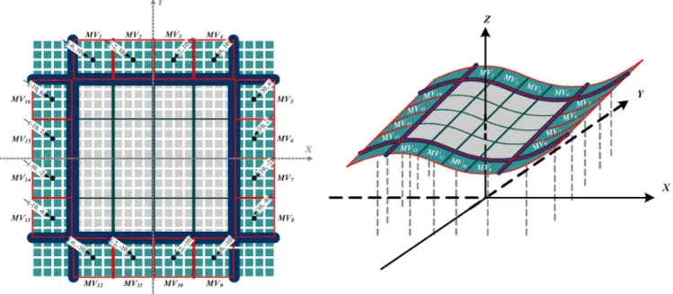
Fig. 12. (a) Left: Coordinates of neighboring 42 4 block centers, (b) Right: The Optimum Regression plane estimated by the surrounding motion vectors.
, Block 16 : ,
re-spectively.
If the interleaving technique or the motion vectors of the nearest surrounding blocks are not available, we can select other motion vectors that are close to the damaged MB to estimate the motion vectors.
An illustration of the coordinates of neighboring 4 4 block centers and their corresponding motion vectors, , ,
, , , , , , , , ,
, , , , , are shown in Fig. 12(a). We have developed the multiple polynomial regression model to reconstruct the corrupted motion vectors based on the corre-sponding positions of the surrounding 4 4 blocks while uti-lizing the highest spatially correlated MVs. While MVs spatially distant from each other still exhibit a small amount of correla-tion, those nearest each other will be favored in this approach as they are most likely to be highly correlative.
The nonlinear multiple polynomial regression model is as fol-lows:
(7) where Z(x, y) is the correlated motion vector; the latter por-tion is the combinapor-tion of the set of unknown coefficients
, that can be calculated by
using the information contained within the surrounding 4 4 blocks; and the error term, , is the representative of the collec-tive unobservable influence of any omitted variable. The value
of the set of coefficients , are
estimated by the minimum of the sum of squares of residuals (method of least squares) as shown in (7). Using least-squares regression to obtain the minimum of , the set of coefficients
, should satisfy the following formula.
(8) In order to give consideration to both the reduction of compu-tation cost and the accurate description of nonlinear movement, we can use the center coordinates and the motion vector value of the corresponding 4 4 block second-order multiple polyno-mial regression (OR) plane for the estimation of missing MVs. For real world image sequencing in H.264/AVC standard, the motion vectors used in interpolation are within a small area, a regression plane not being necessary for more than a third-order multiple polynomial. In contrast, when the movement of sur-rounding blocks is linear, the OR plane will approximate the first-order multiple polynomial regression plane. The OR plane is as follows.
(9) where
The coefficients, , , , , , are calculated by least-squares, using the motion vectors and center coordinates of the corresponding 4 4 blocks.
The estimated motion vectors will then be located on the op-timum regression plane, as illustrated in Fig. 12(b).
The sixteen MVs for each 4 4 block within the damaged MB will be estimated by using the corresponding coordinates of each 4 4 missing block center, and are ( 6, 6), ( 6, 2), ( 2, 6), ( 2, 2), (6, 6), (6, 2), (2, 6), (2, 2), (6, 6), (6, 2), (2, 6), (2, 2), ( 6, 6), ( 6, 2), ( 2, 6), ( 2, 2), as follow.
(10)
3) Realized Candidate MVS: For accurately estimating
the MV from a comparison between the available candidates, we primarily exploit high spatial correlation and the similar Boundary Matching Algorithm (BMA) [32], [46] to evaluate the spatial and temporal candidate MVs of each 4 4 block in the damaged MB; the spatial motion vector is estimated based on the optimum regression plane, whereas the other is the temporally correlated MV of the same spatial position. First, the external 4-pixel-wide boundary of the lost MB is divided into 12 different areas, after which the spatial and temporal MV candidates of the 4 4 block are evaluated in terms of the external boundary matching error (EBME) of the adjacent external boundary pixels of the lost 4 4 block and the same external boundary pixels of the candidate 4 4 block in the previous frame. An illustration of the adjacent external boundary pixels is shown in Fig. 13.
The 4 4 block and its adjacent external boundary pixels are directly above and towards the left, the 4 4 block
Fig. 13. Spatial and temporal MVs of each missing 42 4 blocks are evaluated by comparing the corresponding adjacent external boundary pixels.
and its adjacent external boundary pixels are directly above, the 4 4 block and its adjacent external boundary pixels are directly left, and so on. The estimated MV is that which effec-tively minimizes the adjacent external boundary matching error (AEBME). A formula depicting the minimization of the top-left 4 4 section ( , , and ) is as follows.
The 4 4 block: (11) The 4 4 block: (12) The 4 4 block: (13) where represents the pixels of the current fame, represents the pixels of the reference fame; is the coordinate of the top left pixel of the damaged 4 4 block , is the spatial or temporal MV candidate of block; is the block size within the damaged MB , and is the width of the external boundary , respec-tively. However, the inner corrupted 4 4 blocks ( , , , and ) are all bordered by the outer corrupted blocks and have no adjacent boundary pixels. , for instance, has a limited choice for the adoption of either spatial or temporal MV, which it therefore evaluates by majority decision based on
(14)
If we undertake an analysis of the entire video sequence, the value of each mode could be differentiated, but in order to prohibit two-pass analysis, the probability of all initial modes are equalized. The probability of the maximum likeli-hood of the four partition modes is expressed as
(15) where represents the partition in ; represents the motion vectors of the partition ; represents the hori-zontal character of the motion vector ; represents the vertical character of the motion vector ; represents the number of partitions in the damaged MB
.
The probability of maximum likelihood is evaluated by using the Laplacian-modeled motion field.
(16)
where represents the median of the horizontal character of the motion vector within the partition in ; represents the median of the vertical character of the motion vector within
Fig. 14. Outward spiral scanning path with early stop at point 2.
the partition in ; and are expressed in terms of the absolute difference of the median and , as follows:
(17)
where denotes the number of motion vectors in .We then take the nature log of (16)
(18)
When the different major clusters are too close to separate and classification results in high probability of error in terms of par-titioning, the Bhattacharyya bound is used as the measurement of the separability of two clusters [71], [72].
For Laplacian probability distribution functions, minimum error of a Bayesian classifier for two different clusters is bounded by
(19) Where
(20) We use Bhattacharyya bound , the upper limit of error, and to denote the cluster in the motion field; is the 2-component mean vector and is 2-by-2 covariance matrix, with and as its determinant and inverse, respectively.
In our case, the probabilities of two clusters are initially equal. When between two clusters is large enough , it means the error probability of classification is very small, and then we define two clusters as separable. After the parti-tion mode is decided upon, it can be used to more accurately represent the motion character of the MB. If the damaged MB
Fig. 15. Flowchart for the proposed S/TEC method.
is thought to exhibit low or regular motion (i.e. Container se-quence), the larger block size is more suitable for motion refine-ment; however, if the damaged MB is thought to exhibit higher and irregular motion (i.e. Stefan sequence), smaller block size is more suitable for motion refinement.
5) Motion Refinement: In order to make a refined estimate
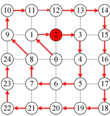
of the replacement MB, we apply motion refinement for each sub-macroblock partition (size of 16 16 or 16 8 or 8 16 or 8 8) of the damaged MB. For each sub-macroblock partition, motion refinement implies that the corresponding mo-tion vector (u, v), the median of the estimated momo-tion vector of the corresponding 4 4 blocks within the sub-macroblock, is used as the starting point for a motion search process to find a more accurate motion vector replacement, for which AEBME (and in this case the external 8-pixel-wide boundary) is em-ployed as the matching measure. To minimize the computational complexity of the motion search process, we propose a novel method: the outward spiral scanning path (Fig. 14), with adap-tive search range and early stop augmenting and improving the search process.
The adaptive search range (ASR) is based on the first adja-cent external boundary matching error at the starting point of the spiral scanning path, along with the motion vector values of all surrounding 4 4 blocks. The ASR for motion search is de-termined by
(21) where
(22)
AEBME(u, v) denotes the first adjacent external boundary matching error at the starting point, (u, v) is the corresponding motion vector for the MB partition, denotes the original residual values of the SADs (sum of absolute difference) in the corresponding surrounding boundary blocks, W is the maximum search size, and are constant factors ( , ), X(MVs) that denotes the x component of the set of mo-tion vectors of corresponding surrounding blocks, and Y(MVs) denotes the y component of the set of the motion vectors of the corresponding surrounding blocks. The early stop of our search process technique is dependent on the proximity of the adjacent external boundary matching error value to the original residual values of the SADs, , in the corresponding boundary blocks. The dynamic threshold is expressed as
(23) where is the total number of pixels in the corresponding boundary blocks, and is the constant factor for each pixel. Occasionally is not available, in which case we need to in-crease in order to calculate the dynamic threshold . If the AEBME of the corresponding surrounding blocks is less or equal than the dynamic threshold , we immediately stop the search for the damaged sub-macroblock. An important point to emphasize is that the use of overlapped block motion com-pensation (OBMC) [32]—the division of the damaged MB into four 8 8 blocks with motion refinement employed for each 8 8 block—results in better video quality when compared to those lacking the use of OBMC, however it causes higher com-putational complexity for a motion search process. Compared with OBMC, the use of VBSMC not only represents the mo-tion characterisic more accurately but also reduces the number of motion search processes from 4 times to 1 4 times for each damaged MB.
Fig. 16. PSNR results at different packet error rates are shown for sequences (a) “Carphone,” (b) “Claire,” (c) “Container,” (d) “Foreman,” (e) “Grandma,” and (f) “Stefan.”
C. Hybrid Error Concealment
The integrated S/TEC classifies the frames of the video se-quence into two categories: the first frame which contains only spatial information, and the succeeding frames which contain both spatial and temporal information. The MBs of the first I-frame are all intra-coded, and in order to recover the impaired MBs we therefore suggest the use of the Intra High-Speed SEC method for utilizing directional spatial intra prediction and spatial redundancy information. With the exception of the first frame, the entire sequence of Intra-frames and Inter-frames exhibiting corrupted blocks can be corrected either by SEC which exploits the spatial redundancy in the same frame, or by TEC which uses the temporal redundancy in video signals. Generally, the success of TEC techniques over those of SEC is attributable to continuous high correlation between the frames of the coded sequence even when there are no available spatial motion vectors in Intra-frames [32]. Although TEC techniques are more effective, these approaches are recognized to fail in the presence of scene changes, very fast or irregular motion, and when objects appear or disappear [32], [73]. In such cases, the SEC algorithm will be adopted to recover damaged MBs. Combining the above discussions, we propose an innovative S/TEC with low complexity, as described in Fig. 15. As errors occur in the initial frame, the missing MBs are recovered using the Intra High-Speed SEC method in order to prevent the propagation of errors to the succeeding inter-coded frames.
After the initial frame, the corrupted MBs are first concealed by the application of specific TEC. If during the motion search process the AEBME of the corresponding surrounding blocks is found to be more than the dynamic threshold , a lack of temporal correlation between current and reference frames can
be assumed, and the proposed hybrid scheme will switch to a SEC method. The dynamic threshold is expressed as
(24) Where is the original residual values of the SADs and is the total number of pixels in the corresponding boundary blocks, and is the constant factor for each pixel. Occasionally is not available, in which case we need to increase in order to calculate the dynamic threshold . For Inter-frames, when the majority of surrounding MBs are coded intra-mode, it is an important indication of the presence of scene changes, the ap-pearance and disapap-pearance of objects, rotation and deformation of objects, and so on. When this occurs, the proposed hybrid scheme will switch to a SEC method. The damaged MB is then concealed by Normal SEC scheme or Intra High-Speed SEC scheme according to the coding mode of the MBs surrounding it; Intra High-Speed SEC is applied when the adjacent MBs are all intra-coded, otherwise the task proceeds by employing Normal SEC.
IV. RESULTS ANDCOMPARISONS
The experimental environment is based around the H.264 reference software of Joint Model (JM) [74] supplied by the JVT [1] committee (Joint Video Team of ISO/IEC MPEG and ITU-T VCEG). The EC algorithms were tested on several standard video sequences in both CIF (352 288) and QCIF (176 144) in order to evaluate the video quality in the experiment. The resolution video sequences were coded at 1 I-frame for every 12 P-frames with a slice size of 536 bytes with random packet lost errors at different specified loss ratios
Fig. 17. PSNR results at different packet error rates are shown for sequences (a) “Container,” (b) “Football,” (c) “Foreman,” (d) “Mobile,” (e) “Stefan,” and (f) “Tempete.”
TABLE II
EXECUTIONTIMESPEED-UP OFSW METHOD
(different rates), which are assumed to be caused by trans-mission errors. Ten different random packet lost errors were used simultaneously at each different specified loss ratio. The average peak signal-to-noise ratio (PSNR) of a video sequence is employed to give a quantitative evaluation of the quality of the reconstructed image.
A. Spatial Error Concealment Results
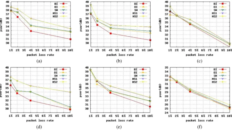
The proposed Normal (SM1) and Intra High-Speed (SM2) SEC methods (Note: we adopt BI method on complex multi-di-rectional edge area by the principle of equity) are compared to the DI SEC method which resembles [24], [30], BI SEC method from [6], [7], and the SEC switching method of DI and BI [32], with each pixel in the damaged MB concealed by linear inter-polation along a one-pixel wide boundary. In order to show the performance of each SEC method, the rates at which random packets are lost, in regard to their effect on intra-frames, are ap-proximately 1%, 2%, 4%, and 10%.
The simulation average PSNR results of different rates of packet erasure are presented only for the specific spatially con-cealed intra-frames. As shown in Fig. 16, our proposed SM1
and SM2 SEC methods result in the best performance in regard to the “Foreman” sequence, one that is significantly better than the BI approach adopted in the JM decoder up to 4.22 dB at the 10% error rate, the DI approach adopted in the JM decoder up to 3.9 dB at the 10% error rate, and the SEC switching method of DI and BI (SW) up to 3.62 dB at the 10% error rate.
Next, we discuss the computational complexity between SM1, SM2, and switching of DI and BI (SW) [32] SEC methods, because the SW [32] SEC methods make an assured calculation of the total amount of Sobel filter for the pixels of each available MB surrounding that which is damaged. Table II shows the speed-up factors of Normal (SM1) and Intra High-Speed (SM2) SEC methods in comparison to the SW [32] SEC method based on the execution time of total SEC processes at the error rate of 1% and 4%.The results show that the SM1 and SM2 SEC methods significantly speed up when compared to the SW [32] SEC method, because the complexity of the process of edge direction detection is reduced.
B. Temporal Error Concealment Results
In the TEC scenario, we assume that packet erasure has not occurred on the initial decoded frame. The performance of the proposed TEC method is compared to the JM method by using several standard video sequences (with the exception of the first frame of each sequence) at the 1%, 5% and 10% erasure rates. Fig. 17 illustrates that the proposed TEC method outperforms the JM method. The “Foreman” video sequence is 3.89 dB, the “Mobile” video sequence is 3.5dB, the “Stefan” video sequence is 2.75 dB, the “Football” video sequence is 2.21 dB, the “Con-tainer” video sequence is 1.94 dB, and the “Tempete” video se-quence is 1.76 dB, with all sese-quences at the 10% erasure rate.
Fig. 18. PSNR results at different packet error rates are shown for sequences (a) “Container,” (b) “Football,” (c) “Foreman,” and (d) “Sefan.”
TABLE III
VBSMC RESULTSCOMPAREDWITHOBMC
In [32], it is proven that motion refinement including the three step search approach and the use of OBMC is a useful step in the TEC method. Now we will compare video quality and computa-tional complexity of the VBSMC with those of the OBMC [32], in effort to discern the more beneficial of the two. In order to compare computational complexity and performance, the pro-posed TEC method featuring the part of VBSMC is substituted with OBMC, and the remainder is fixed in accordance with the total TEC scheme. Table III shows the resulting performance of VBSMC using OBMC as the basis at the 5%, 10%, and 20% erasure rates. The average speed-up of VBSMC was found to be 1.12 times faster than that of OBMC for TEC process time, with VBSMC PSNR improvements of up to 0.09 dB more than OBMC. We also measured the performance of the proposed spiral motion search process with adaptive search range and early stop technique (SMS-ASRES), as well as for comparison to the three step search (TSS) approach [32]. Table IV shows the resulting performance of the proposed SMS-ASRES technique using the TSS process as the basis with the proposed TEC re-mainder fixed at the 5%, 10%, and 20% erasure rates. Our pro-posed SMS-ASRES technique on average achieves a total TEC
TABLE IV
SMS-ASRES RESULTSCOMPAREDWITHTSS
process time of 0.94 that of the TSS process and video quality of up to 0.36 dB better than the TSS process.
Clearly, the results demonstrate that the proposed motion re-finement of the temporal concealment process has a strong pos-itive effect on performance of video quality and computational complexity.
C. Hybrid Error Concealment Results
In the final part of this section, the overall performance of the proposed S/TEC method is compared to the widely-known JM method. Figs. 18 and 19 show the results of the FMO and non-FMO cases at the 1%, 5% 10% and 20% erasure rates. The proposed S/TEC method significantly outperforms the JM method, especially at high (20%) packet error rates. During the concealment of the damaged MB, it is discovered that when the proposed hybrid integrated scheme is employing the SEC method, the technique of choice will usually be intra High-Speed SEC because of the high percentage of intra-coded ad-jacent MBs. The adoption of intra High-Speed SEC is highly beneficial because it requires far less time than Normal SEC. While the total S/TEC computational complexity is higher than
Fig. 19. PSNR results at different packet error rates are shown for sequences (a) “Container,” (b) “Football,” (c) “Foreman,” and (d) “Sefan.”
the JM method by 8%, quality is also higher, showing gains of up to 10.62dB.
V. CONCLUSION
In this work, we propose an efficient and integrated novel spatial and temporal error scheme that offers excellent gains of up to 10.62dB compared to that of the H.264 JM decoder. The following series of EC methods are proposed.
Normal SEC is a novel hybrid method which uses DI, BI, multi-DI, or BMN targeted at any condition. Intra High-speed SEC is a proposed hybrid method which uses DI, BI, multi-DI, or BMN can be invaluable when targeted at intra coded block which utilizes the H.264/AVC coding tool of directional spa-tial domain intra prediction for intra coding in order to reduce the number of calculations needed to ascertain the quantity of direction edge filter, and in so doing reduces enormously the overall computational complexity. The proposed SEC schemes offer significant performance gains in comparison to other state of the art methods. An optimized TEC algorithm with several novel techniques: the spatial damaged motion vectors are es-timated based on the optimum regression plane, suitable MB partition is based on predictive motion vectors of the Laplacian distribution model, a significant speed-up on motion refinement with variable block size motion compensation, and early stop by dynamic threshold. The proposed integrated S/TEC method fulfills the role of control-whole-scheme that utilizes the char-acteristic continuous high correlation between the frames of the video sequences to adopt the TEC method precedence over SEC methods and intellectual switch to a SEC method by the corre-sponding surrounding blocks’ information. However, the inte-grated S/TEC method achieves excellent gains of up to 10.62dB when compared to that of the JM method while showing an as-sociative computation complexity increase of 8% ([32] states a
value of around 15%). It is concluded that our proposed inte-grated S/TEC method is effective and fully utilizes the H.264 video streaming characteristic.
REFERENCES
[1] Joint Video Team (JVT) of ISO/IEC MPEG and ITU-T VCEG, “Draft ITU-T Recommendation and Final Draft International Standard of Joint Video Specification,” 2003, ITU-T Rec. H.264 | ISO/IEC 14496-10 AVC.
[2] T. Wiegand, G. J. Sullivan, G. Bjntegaard, and A. Luthra, “Overview of the H.264/AVC video coding standard,” IEEE Trans. Circuits Syst.
Video Technol., vol. 13, no. 7, pp. 560–576, July 2003.
[3] Y. Wang, S. Wenger, J. Wen, and A. K. Katsaggelos, “Error resilient video coding techniques,” IEEE Signal Processing Magazine, vol. 17, no. 4, pp. 61–82, July 2000.
[4] J. W. Suh and Y. S. Ho, “Error concealment techniques for digital TV,”
IEEE Trans. Broadcasting, vol. 48, no. 4, pp. 299–306, Dec. 2002.
[5] Y. Wang and Q. F. Zhu, “Error control and concealment for video com-munication: a review,” Proc. IEEE, vol. 86, no. 5, pp. 974–997, May 1998.
[6] P. Salama, N. B. Shroff, and E. J. Delp, “Error concealment in encoded video streams,” in Signal Recovery Techniques for Image and Video
Compression and Transmission, A. K. Katsaggelos and N. P.
Galat-sanos, Eds. Norwell, MA: Kluwer, 1998, ch. 7.
[7] Y. K. Wang, M. M Hannuksela, V. Varsa, A. Hourunranta, and M. Gabbouj, “The error concealment feature in the H.26L test model,” in
Proc. Int. Conf. Image Processing (ICIP), Rochester, New York, USA,
Sept. 2002, vol. 2, pp. 729–732.
[8] K. Meisinger and A. Kaup, “Spatial error concealment of corrupted image data using frequency selective extrapolation,” in Proc. Int. Conf.
Acoust., Speech, Signal Process. (ICASSP), 2004, pp. 209–212.
[9] Y. Wang, Q. F. Zhu, and L. Shaw, “Maximally smooth image recovery in transform coding,” IEEE Trans. Commun., vol. 41, pp. 1544–1551, Oct. 1993.
[10] Q. F. Zhu, Y. Wang, and L. Shaw, “Coding and cell loss recovery for DCT-based packet video,” IEEE Trans. Circuits Syst. Video Technol., vol. 3, pp. 248–258, June 1993.
[11] W. Zhu and Y. Wang, “A comparison of smoothness measures for error concealment in transform coding,” in Proc. SPIE Conf. Visual
Com-munication and Image Processing, Taipei, Taiwan, 1995, vol. II, pp.
1205–1214.
[12] J. W. Park, J. W. Kim, and S. U. Lee, “DCT coefficients recovery-based error concealment technique and its application to MPEG-2 Bit stream error,” IEEE Trans. Circuits and Systems for Video Technology, vol. 7, pp. 845–854, Dec. 1997.
block-based image coding techniques—A fuzzy logic approach,” IEEE
Trans. Image Processing, vol. 4, pp. 259–273, Mar. 1995.
[19] H. Sun and W. Kwok, “Concealment of damaged block transform coded images using projection onto convex set,” IEEE Trans. Image
Processing, vol. 4, pp. 470–477, Apr. 1995.
[20] K. Jung, J. Chang, and C. Lee, “Error concealment technique using projection data for block-based image coding,” in Proc. SPIE Conf.
Visual Communication and Image Processing, 1994, vol. 2308, pp.
1466–1476.
[21] I. V. Bajic, “Adaptive MAP error concealment for dispersively packe-tized wavelet-coded images,” IEEE Trans. Image Process, vol. 15, no. 5, pp. 1226–1235, May 2006.
[22] Z. Wang, Y. Yu, and D. Zhang, “Best neighborhood matching: An in-formation loss restoration technique for block-based image coding sys-tems,” IEEE Trans. Image Process., vol. 7, no. 7, pp. 1056–1061, Jul. 1998.
[23] S. Aign and K. Fazel, “Temporal and spatial error concealment tech-niques for hierarchical MPEG-2 video codec,” in Proc. ICC, Jun. 1995, vol. 3, pp. 1778–1783.
[24] J. W. Suh and Y. S. Ho, “Error concealment based on directional in-terpolation,” IEEE Trans. Consumer Electron., vol. 43, pp. 295–302, Aug. 1997.
[25] W. Kwok and H. Sun, “Multi-directional interpolation for spatial error concealment,” IEEE Trans. Consumer Electron., vol. 39, no. 3, pp. 455–460, Aug. 1993.
[26] W. Zeng and B. Liu, “Geometric-structure-based error concealment with novel applications in block-based low-bit-rate coding,” IEEE
Trans. Circuits and Systems for Video Tech, vol. 9, no. 4, pp. 648–665,
1999.
[27] W. Y. Kung, C. S. Kim, and C. Kuo, “A spatial-domain error conceal-ment method with edge recovery and selective directional interpola-tion,” in Proc. of IEEE International Conference on Acoustics, Speech,
and Signal Processing, Apr. 2003, vol. 5, pp. 6–10.
[28] J. Chen, J. Liu, X. Wang, and G. Chen, “Modified edge-oriented spa-tial interpolation for consecutive blocks error concealment,” in Proc. of
IEEE International Conference, Image Processing (ICIP), Sept. 2005,
vol. 3, pp. 11–14.
[29] Y. Zhao, D. Tian, M. M. Hannukasela, and M. Gabbouj, “Spatial error concealment based on directional decision and intra prediction,” in
Proc. ISCAS, 2005, vol. 3, pp. 2899–2902.
[30] Y. Xu and Y. Zhou, “H.264 video communication based refined error concealment schemes,” IEEE Trans. Consum. Electron., vol. 50, no. 4, pp. 1135–1141, Nov. 2004.
[31] Z. Rongfu, Z. Yuanhua, and H. Xiaodong, “Content-adaptive spatial error concealment for video communication,” IEEE Trans. Consum.
Electron., vol. 50, no. 1, pp. 335–341, Jan. 2004.
[32] D. Agrafiotis, D. R. Bull, and C. N. Canagarajah, “Enhanced error con-cealment with mode selection,” IEEE Trans. Circuits Syst. Video
Tech-nology, vol. 16, no. 8, pp. 960–973, Aug. 2006.
[33] Q. Peng, T. Yang, and C. Zhu, “Block-based temporal error conceal-ment for video packet using motion vector extrapolation,” in IEEE 2002
International Conference on Communications, Circuits and Systems and West Sino Expositions, Jun. 29–July 1 2002, vol. 1, pp. 10–14.
[34] P. Haskell and D. Messerschmitt, “Resynchronization of motion com-pensated video affected by ATM cell loss,” in Proc. ICASSP, Mar. 1992, vol. 3, pp. 545–548.
[35] S. Valente, C. Dufour, F. Groliere, and D. Snook, “An efficienct error concealment implementation for MPEG-4 video streams,” IEEE Trans.
Consumer Electronics, vol. 47, no. 3, pp. 568–578, Aug. 2001.
[36] B. Yan and K. W. Ng, “A novel selective motion vector matching al-gorithm for error concealment in MPEG-4 video transmission over error-prone channels,” IEEE Trans. Consumer Electronics, vol. 49, no. 4, pp. 1416–1423, Nov. 2003.
[37] J. Zhang, J. F. Arnold, and M. R. Frater, “A cell-loss concealment technique for MPEG-2 coded video,” IEEE Trans. Circuits Syst. Video
Technol., vol. 10, no. 4, pp. 659–665, Jun. 2000.
media, 2002, vol. 2532, pp. 425–433.
[43] J. Zheng and L.-P. Chau, “Error-concealment algorithm for H.26L using first-order plane estimation,” IEEE Trans. Multimedia, vol. 6, no. 6, pp. 801–805, Dec. 2004.
[44] J. Zheng and L.-P. Chau, “Efficient motion vector recovery algorithm for H.264 based on a polynomial model,” IEEE Trans. Multimedia, vol. 7, no. 3, pp. 507–513, Jun. 2005.
[45] J. Zheng and L. P. Chau, “A motion vector recovery algorithm for dig-ital video using Lagrange interpolation,” IEEE Trans. Broadcast., vol. 49, no. 4, pp. 383–389, Dec. 2003.
[46] W. M. Lam and A. R. Reibman, “Recovery of lost or erroneously received motion vectors,” in Proc. Int. Conf. Acoust., Speech Signal
Process. (ICASSP), 1993, pp. V-417–V-420.
[47] G. Sullivan, T. Wiegand, and K.-P. Lim, “Joint model reference en-coding methods and deen-coding concealment methods,” Doc. JVT-I049, Sep. 2003.
[48] Y. Kuo and S.-C. Tsao, “Error concealment based on overlapping,” in
Proc. SPIE, Jan. 2002, vol. 4671, pp. 146–153.
[49] T. Chen, “Refined boundary matching algorithm for temporal error concealment,” in Proc. Packet Video, 2002, pp. 875–887.
[50] T. I. Wen and H. Chung-Lin, “Hybrid cell loss concealment methods for MPEG-II base packet video,” Signal Processing—Image Commun., vol. 9, no. 2, pp. 99–124, Jan. 1997.
[51] C. T. Hsu, M. J. Chen, W.-W. Liao, and S.-Y. Lo, “High-performance spatial and temporal error-concealment algorithms for block-based video coding techniques,” ETRI J., vol. 27, no. 1, pp. 53–63, 2005. [52] M. C. Hong, H. Scwab, L. Kondi, and A. K. Katsaggelos, “Error
concealment algorithms for compressed video,” Signal Process, Image
Commun., vol. 14, pp. 473–492, 1999.
[53] L. W. Kang and J. J. Leou, “A hybrid error concealment scheme for MPEG-2 video transmission based on best neighborhood matching algorithm,” J. Vis. Commun. Image Represent., vol. 16, no. 3, pp. 288–310, Jun. 2005.
[54] Y. C. Lee, Y. Altunbasak, and R. Mersereau, “Multiframe error con-cealment for MPEG-coded video delivery over error-prone networks,”
IEEE Trans. Image Process., vol. 11, no. 11, pp. 1314–1331, Nov.
2002.
[55] Y. O. Park, C.-S. Kim, and S.-U. Lee, “Multi-hypothesis error conceal-ment algorithm for H.26L video,” in Proc. Int. Conf. Image Processing
(ICIP), 2003, pp. 465–468.
[56] S. Belfiore, M. Grangetto, E. Magli, and G. Olmo, “Concealment of whole-frame losses for wireless low bit-rate video based on multiframe optical flow estimation,” IEEE Trans. Multimedia, vol. 7, no. 2, pp. 316–329, Apr. 2005.
[57] P. Baccichet, D. Bagni, A. Chimienti, L. Pezzoni, and F. Rovati, “Frame concealment for H.264/AVC decoders,” IEEE Trans.
Con-sumer Electronics, vol. 51, no. 1, pp. 227–233, Feb. 2005.
[58] G. S. Yu, M. M.-K. Liu, and M. W. Marcellin, “POCS-based error concealment for packet video using multiframe overlap information,”
IEEE Trans. Circuits Syst. Video Technol., vol. 8, pp. 422–434, Aug.
1998.
[59] W. J. Chu and J.-J. Leou, “Detection and concealment of transmission errors in H.261 images,” IEEE Trans. Circuits Syst. Video Technol., vol. 8, pp. 74–84, Feb. 1998.
[60] L. Su, Y. Zhang, W. Gao, Q. Huang, and Y. Lu, “Improved error con-cealment algorithms based on H.264/AVC non-normative decoder,” in
Proc. Int. Conf. Multimedia Expo (ICME), 2004, pp. 1671–1674.
[61] M. H. Jo and W.-J. Song, “Error concealment for mpeg-2 video de-coders with enhanced coding mode estimation,” IEEE Trans. Consum.
Electron., vol. 46, no. 4, pp. 962–969, Apr. 2000.
[62] L. Tang, “Combined and iterative form of spatial and temporal error concealment for video signals,” IEEE Trans. Broadcast., vol. 52, no. 3, Sept. 2006.
[63] S. C. Huang, S. C. Cheng, and S. W. Chou, “Efficient adaptive error concealment technique for video decoding system,” IEEE Trans.
[64] S. Cen and P. C. Cosman, “Decision trees for error concealment in video decoding,” IEEE Trans. Multimedia, vol. 5, no. 1, pp. 1–7, Mar. 2003.
[65] E. R. Davies, Machine Vision. San Diego: Academic Press Inc., 1990. [66] E. Ong, W. Lin, Z. Lu, S. Yao, and M. Etoh, “Visual distortion as-sessment with emphasis on spatially transitional regions,” IEEE Trans.
Circuits Syst. Video Technol., vol. 14, no. 4, pp. 559–566, Apr. 2004.
[67] X. Ran and N. Farvardin, “A perceptually motivated three component image model—Part I: description of the model,” IEEE Trans. Image
Process., vol. 4, pp. 401–415, Apr. 1995.
[68] C. E. Shannon, “A mathematical theory of communication,” Bell Sys.
Tech. J., vol. 27, pp. 379–423, 1948, and 623-656.
[69] Y. W. Huang, B.-Y. Hsieh, T.-C. Chen, and L.-G. Chen, “Analysis, fast algorithm, and VLSI architecture design for H.264/AVC intra frame coder,” IEEE Trans. Circuits Syst. Video Technol., vol. 15, pp. 378–401, Mar. 2005.
[70] S. Wenger, “H.264/AVC over IP,” IEEE Trans. Circuit Syst. Video
Technol., vol. 13, no. 7, pp. 645–656, Jul. 2003.
[71] T. Y. Kuo and C. H. Chan, “Fast variable block size motion estima-tion for H.264 using likelihood and correlaestima-tion of moestima-tion field,” IEEE
Trans. Circuits Syst. Video Technology, vol. 16, no. 10, pp. 1185–1195,
Oct. 2006.
[72] O. D. Richard, E. H. Peter, and G. K. David, Pattern Classification. New York: Wiley-Interscience, 2000, pp. 46–48.
[73] L. Atzori, F. G. B. De Natale, and C. Perra, “A spatio-temporal conceal-ment technique using boundary matching algorithm and mesh-based warping (BMA-MBW),” IEEE Trans. Multimedia, vol. 3, no. 3, pp. 326–338, Sep. 2001.
[74] H.264/AVC Reference Software JM [Online]. Available: http://bs. hhi.de/~suehring/tml/
Shih-Chia Huang received a master’s degree in
computer science from National Chiao Tung Uni-versity, Taiwan, R.O.C. in 2005. He is currently working toward a doctoral degree in the Electrical Engineering Department, National Taiwan Univer-sity, Taiwan, R.O.C. His research interests include image and video coding, video transmission, error resilience and concealment techniques, digital signal processing, Java processor design, and embedded software and hardware co-design.
Sy-Yen Kuo ((S’85-M’88-SM’98-F’01) is a Chair
Professor and Dean of the College of Electrical and Computer Engineering, National Taiwan University of Science and Technology, Taipei, Taiwan. He is also a Distinguished Professor at the Department of Electrical Engineering, National Taiwan University where he is currently taking a leave of absence and was the Chairman at the same department from 2001 to 2004. He received the BS (1979) in Electrical Engineering from National Taiwan University, the MS (1982) in Electrical & Computer Engineering from the University of California at Santa Barbara, and the PhD (1987) in Computer Science from the University of Illinois at Urbana-Champaign. He spent his sabbatical years as a Visiting Professor at the Computer Science and Engineering Department, the Chinese University of Hong Kong from 2004-2005 and as a visiting researcher at AT&T Labs-Research, New Jersey from 1999 to 2000, respectively. He was the Chairman of the Department of Computer Science and Information Engineering, National Dong Hwa University, Taiwan from 1995 to 1998, a faculty member in the Department of Electrical and Computer Engineering at the University of Arizona from 1988 to 1991, and an engineer at Fairchild Semiconductor and Silvar-Lisco, both in California, from 1982 to 1984. In 1989, he also worked as a summer faculty fellow at Jet Propulsion Laboratory of California Institute of Technology. His current research interests include dependable systems and networks, software reliability engineering, mobile computing, and reliable sensor networks.
Professor Kuo is an IEEE Fellow. He has published more than 270 papers in journals and conferences, and also holds several patents. He received the dis-tinguished research award between 1997 and 2005 consecutively from the Na-tional Science Council in Taiwan and is now a Research Fellow there. He was also a recipient of the Best Paper Award in the 1996 International Symposium on Software Reliability Engineering, the Best Paper Award in the simulation and test category at the 1986 IEEE/ACM Design Automation Conference(DAC), the National Science Foundation’s Research Initiation Award in 1989, and the IEEE/ACM Design Automation Scholarship in 1990 and 1991.