2629 IEEE TRANSACTIONS ON MAGNETICS, VOL. 32, NO. 4, JULY 1996
The Construction of
a %Pole Prototype for SRRC
U-10 Undulator
C.H. Chang, L.H. Chang, H.H. Chen, T.C. Fan, C.S. Hwang*, D.N. Guo, J.Y. Hsu, F.Y. Lin, T.F. Lin, Ch. Wang, S.T. Yeh Synchrotron Radiation Research Center, Hsinchu, Taiwan
*
also Department of Electrophysics, National Chiao Tung University, Hsinchu, Taiwan G. J. HwangDepartment of Power Mechanical Engineering, National Tsing Hua University, Hsinchq Taiwan P.K. Tseng
Department of Physics, National Taiwan University, Taipei, Taiwan Abstract--A %pole undulator prototype with a magnetic
period length of 10 cm was designed and constructed to
examine the mechanical and magnetic field performance. The hybrid permanent magnet structure was optimized by using 2D
"PANDIRA" and 3D "TOSCA" magnetostatic codes. A half period magnet model was also fabricated to verify the magnetic field strength on-axis and the transverse field roll-off within
0.1 % in the good field region of k 10 mm at a minimum gap of 22 mm. The end pole configurations, as equipped with either two tunable permanent magnetic rotators or steering coil correctors were designed for minimizing the deviation of the magnetic field strength integrals. The magnet structures were mounted on a 2 meter long C-frame support structure in which the gap could be moved in parallel and phase motion. The field characteristics and measurement results between the adjustable gap undulator (AGU) and the hybrid adjustable phase undulator (MU) were also presented.
I. INTRODUCTION
A third generation 1.3 GeV storage ring has been operated in Taiwan Synchrotron Radiation Research Center (SRRC) since April 1994. The storage ring has four 6 m long straight sections for installing various insertion devices. The U10 undulator is the second insertion device to be constructed and installed in the ring. The U10 undulator was designed to produce the first harmonic spectra photon source in the 5 to 100 eV energy spectrum. The high
brightness photon source is estimated to achieve higher than 10l6 photons/sec nun2 200 mA 0.1 % BW with nominal emittance and forty periods.
The undulator generally relies on a change of gap between the upper and lower magnet arrays to adjust the field strength.
An alternative method is an adjustable phase undulator ( M u )
to slide a half-period length magnet array with respect to the other array along the electron beam direction at constant gap. The APU offers a relatively simple mechanical apparatus to precisely control the linear motion in a short range [I]. To our knowledge, the hybrid magnet structure
M U
has not yet been carried out on storage rings. Therefore, in this study, ashort hybrid magnetic structure prototype is constructed to examine the field performance of the adjustable gap
undulator (AGU) and the adjustable phase undulator (APU). Table 1 lists the main parameters of the U10 undulator.
TABLE 1
THE MAIN PARAMETERS OF U10 UNDULATOR
Period length
Overall length Minimum gap
FiEective peak field (a22 "gap) Peak field uniformity ( A B B ) m Transverse rolloff in +- lcm HorizontzVvertical integrated dipole field Integrated quadnrpole Pole width Pole height Pole thickness 10 cm 1 4 m 2.2 cm > 0.945 T 5 0.5 % 5 0.1 % - S 1 Gm 5 50 G 8.4 Cm 6.2 Cm 1.6 m
Number of blocks per bar-period 6
Fig, 1 Half Period Pole Assembly
11. MAGNET DESIGN \ 62 I Block Keeper 0018-9464/96$05.00 B 1996 IEEE
2630
A . Period Magnetic Structure Design
A period length of 10 cm with a peak field of 0.945 T was selected for optimizing the first harmonics energy spectrum and photon brightness at 22 mm gap. A Halbach hybrid magnet structure was used for achieving a high field requirement at a given small gap to period ratios (2.2/10) and was less sensitive to the dipole field strength error. Because the volumes of pole and magnet determine the field performance and the cost, the peak field in the midplane was optimized at a gap of 22 mm. Following the analysis of Halbach theory, several configurations associated with the ratio of pole thickness to period length, the height of permanent magnet and overhang and the third harmonic content were studied by using 2D magnetostatic code PANDIRA [2]. Optimization of the geometrical parameters
was determined and is shown in Figure 1 to achieve the maximum field on axis and lower third harmonics. Moreover, a 1 mm chamfering of pole tip was chosen to avoid saturation. Next, a 3 mm recess between the pole and magnet
was selected to fine tune the deviation of peak field by iron
shims and to avoid the demagnetizing field in the lower edge of the magnet. The 2 D simulation estimated a peak field 10 % higher than the field requirement to compensate the 3D effect. Transverse widths of the pole and permanent magnet were determined to satis@ the roll-off within 0.1 % on transverse field uniformity. The field distributions with the pole width and magnet overhangs were confirmed by using 3D magnetostatic code TOSCA and given the roll off within 0.1 % at 8.0 mm at 22 mm gap. Next, the magnetic structure design and field performance were verified by constructing a full-size pole assembly with the magnetic mirror plates. Figure 2 compare the measured and calculated normalized profiles of a transverse field roll-off.
I E 0.9
3
0.8 I U 8 0.7 0.6 - 0 G & (1.3E
a
0.2 0.43
0 3 0. I 0 -la, -50 0 50 Trsnsvcnc Coordinate (mm)- measured data
.
3D TOSCA ulculntcdFig. 2 Normalized profile between measured and calculated field strengths m transverseposition at 22 mm gap
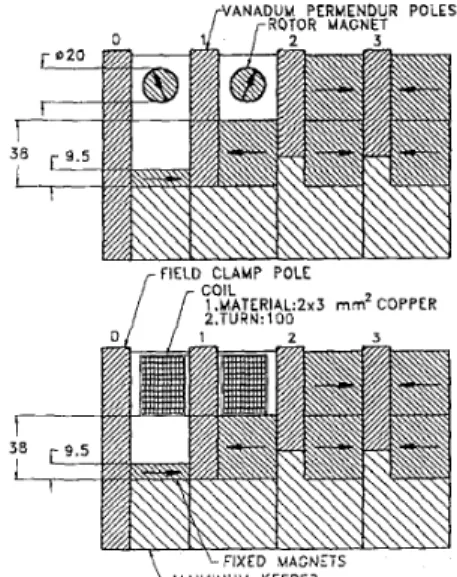
B. End Pole Magnetic Design
In order to compensate for the first integrals of a vertical field, the end pole configuration was designed to nunimize the deviation of the first dipole magnetic field integral at all operating gaps. Two different schemes of end pole were studied and are shown in Figure 3. A passive scheme is
composed of two sets of fixed permanent magnets and two
tunable permanent magnetic rotors. Another scheme incorporates two steering coils instead of the tunable permanent magnetic rotors. The maximum deviation of the first field integrals depends on the size of fixed magnets. The variation of dipole steering around 1 G-m is designed to be gap independent of optimized heights of fixed magnets. The fixed magnets are determined as a 1/2 height magnet and a 1/8 height magnet, respectively. A 20 mm diameter tunable rotor with 2 O adjustment steps is designed to fine tune the
integrated dipole field. The capability of rotor steering is around 10,000 G-cm at all operating gaps. Because of the three dimensional end field effect and the random field errors, the integrated dipole field simulations and the actual device differ slightly in the gap dependency. The end pole assemblies in the prototype are designed here as a removable part for relatively easy disassembly to adjust the size of the fixed magnets and rotors. The end return flux yokes are connected to minimize the fringe field effect on both of the field clamps. A situation is considered in which compensation of the first integrated field can not be satisfied by one rotor set for all operating gaps. Therefore, the tunable rotor is replaced by the steering coils to avoid a more complicated rotor driving mechanism. The steering coils can be tuned to correct the vertical integrated fields as a function of gap. The steering coils are wound with a 2x3 mm copper conductor. A current density of 3 Nmm2 is limited for an air cooled coil. A cumulative total of 200 turns of coils is connected in series.
P N A D U M r R O T O R PERMENDUR MAGNET POLES
/fIE; CLAMP POLE COIL
1 .MATERIAL:ZxS mmz COPPER 2.TURN: 100
\ - A L U M I N U M KEEPE?
263 I
111. MAGNET CONSTRUCTION
A half period magnetic assembly consists of a vanadium permendure pole and six NdFeB permanent magnet blocks surrounded by an aluminum keeper, as shown in Figure 1. 150 NdFeB permanent magnet blocks were purchased from Taiwan High-End Metal Corporation. A magnet block (3.8 x 3.8 x 3.4 cm3) has an average magnetization of 1.22 T and intrinsic coercive force of 1200 W m . The variation of M z
from block to block af€ects the variation in the magnetic field from pole to pole. The second s i f l c a n t characteristic of block is the disorientation of magnetic moments (Mx and My), thereby causing vertical or horizontal field errors in the midplane of gap. The dipole moment variation and orientations error were limited on an order of 1 % and 2 O
.
A fully automated Helmholtz coil measurement system was designed here and used to measure the three components of the magnetic moment, M i , Mx and My, respectively. A reference block was measured to verlfy a long term system repeatability within an error of 0.04 %. The block magnet properties depend on the average direction of the net moment and uniformity. The measured data of blocks were used in a sorting algorithm. The principal sorting criteria was designed according to the sum of the square of M x and My and the
alloy A6061 plate. The structure must be sufficiently rigid to maintain a gap variation at a maximum magnetic force of 10,000 kgw. Moreover,
a
stress analysis of the support structure is performed by using a computer code"ANSYS"
to investigate the structure deformation. These results indicate that maximum deformation in the vertical position is 1.7microns.
The drive train system provides the gap adjustment mechanism to separate the magnetic structure from gap 2.2 to 23 cm. The drive system includes four independent drive train groups in a standard structure. Each drive train group is composed of a brushless servo motor, gear reducer, torque limiter and worm gear screw jack. The position accuracy is determined by four optical linear encoders mounted on both ends of a strong back beam. A gap reproducibility of 7
microns without the magnetic force was verified by using the laser interferometer in the test run.
The phase motion design incorporates two slide rails under a base plate that are capable of longitudinally sliding along a half-period length on the lower backing beam. The motion mechanism is designed to maintain tolerances under the maximum magnetic force at 25 mm phase position. Also, a linear encoder with a resolution of 1 micron is mounted on a backing beam to measure the phase position.
smallest -values of (Mx2+Myz)~ these values were- arranged close to the beam position [3]. The standard deviation of average of M z values reduce from 1.44 % to 0.16 % after the magnet sorting results. Moreover, the square magnet blocks can be rotated in x and y directions; otherwise, it's position is rearranged in the same group to cancel out the disorientation and eliminate the integrated multipole terms.
The random field error A B B is specified to be less than 0.5 %, depending on such factors as the mechanical tolerances of the pole and magnet placement and pole shape. The permanent magnet blocks were carefully positioned relative to the pole face, then bonded into these assemblies to produce a basic half-period magnet assembly, The bonding fixture
was
used to safety clamp the magnet block and glue them together with pole and keeper assembly. The pole height and magnet keeper were measured and matched for averaging the mechanical errors. Each of the pole assemblies was accurately pinned by two dowel pins on the base plates to ensure the periodicity. Finally, flatness of all poles on each base plate was measured and shimmed so that tolerancerequirements were met within twenty microns. Fig 4. T h e 2 meter lung support slrudure ofUl0 imdulator.
v.
MAGNETIC MEASUREMENTSIV. SUP~ORT STRUCTURE AND
D
m
S Y ~ MThe support structure consists
of
WO C-frame The magnetic field quality is determined by the storage ring requirements and the acceptable spectral performance. A5 meter long measurement bench has been set up for measuring the insertion device [4]. The "on the fly" Hall- probe field measurement technique is used by moving a probe along the beam direction on the bench. The Hall probe data are taken twelve times and an average field strength is given. structures and two strong backing beams. Figure 4 exhibits a
2 m long standard support structure. A C-shape structure is designed to allow for easy installation ofthe vacuum chamber and for easy magnetic measurements. The support structure offers the framework to hold the magnetic structure and drive system. The support structure is made of an aluminum
2632
The vertical (By) and longitudinal (Bz) field components are measured by using a Group3 Hall probe. The Hall-probe is precisely rotated 90 O around the x axis to measure the
longitudinal field Bz. Since both fields are simultaneously present in the plane, the tilt angle between the Hall plate and the magnetic midplane must be carefully aligned and adjusted for minimizing the planar Hall effect. Furthermore, the standard deviation of field integral measurement was verified be less than 30 G-cm.
o o o o o with trim m a g n e t I without lrlm m a g n e t - e -m f 5 0 0 - S U - 5 300- G
-
::
100-; -
U -100- 2 -Transverse Position x (mm)Fig 5. First field integrals versus the tratlsverse positicn x at 22 mm gap
After the field measurement and analysis, a quadrupole field integral errors occurred over a transverse range of 35
mm at a 22 mm gap as shown in Figure 5. The field errors are caused from the orientation errors and M z variations of permanent magnet blocks. The longitudinal magnetic field integral errors are corrected by mounting a small trim magnet block (18x18~8 "3) on the end pole so as to compensate the integrated field errors. Those results indicated that the field integrals in transverse position are improved and satisfy the requirement of multipole components in a good field region. The variations of first field integral on axis were measured within F 300 G-cm from 22 mm to 80 mm gap. The first magnetkfield integral on axis is shown in Figure 7 as a function of magnet gap.
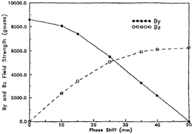
The phase motion is varied from zero to half period length at 28 mm gap. The on-axis vertical (By) and longitudinal (Bz) fields are almost in the phase, regardless of the phase shift between the hybrid magnet structure arrays. Fig. 6 shows both vertical and longitudinal fields with a phase shift from 0 to 50 mm at 28 mm gap. Additionally, the variations of first vertical Geld integrals on axis are measured by phase motion from 0 to 40 mm at 28 mm gap. Figure 7
compares the first field integrals on axis for the AGU and
APU as a function of vertical field strength on axis.
VI. CONCLUING REMARKS
The APU provides a relatively simple mechanical apparatus. In this study, the hybrid APU is tested, with these results demonstrating that the on-axis vertical and longtudinal
fields are in phase. The first vertical field integrals on axis without the end field compensation are measured, revealing an insignificant difference between the AGU and APU. The transverse multipole integrals are corrected by using the small trim magnets on the end pole. In the near future, we expect the 9 pole prototype undulator to be installed in the ring to examine the performance of the hybrid adjustable phase undulator. 1 ww.0 I . , , , , 10 20 30 40 Pham Shllf (mm) 0.0 I
Fig 6 Vertical and lcngitudinal field profiles are measured by phase shift from
Oto50mm at2Xmmgap
-0.8 4 . 0 4 . 4 -0.2 O b
-7.00
-1.0
Centml Pole Vedlcal fleld Strength By (Tsda)
Fig. 7 Field integrals on axis as a fundion of vertical field between AGU and A€U
REFERENCES
[ 1 ] R. Carr, "Adjustable phase unddator", Synzlch. Rad News 5 (4) 1992
[21 L H Chane Ch. Wmg, C.H. Chang, P.K. Tsen& "On Optimization of
Periodic Magnetic Strudure for Undulator UlOISRRC", Proce&&s ofthe
9th Conference on Mapetkm & Magnetic Tedmologies, ~452~457,1994.
Taiwan.
[3] D. Humphries, E. Hoya, B. Kincaid, S. Marks, R. Srhluta "Mapet Sorting Algorithm for Insertion Devices for the Advanced Light Source"
Proceedings of the 13th Intematicnal CcaCaence on Magnet Ttdmology, Victoria, Canada, 1993.
[4] STI Optrmics, Inc. "Magnetic Measurement Report for SRRCl.8 T Wiggler Mapet", Dec, 1994