1456 OPTICS LETTERS / Vol. 19, No. 18 / September 15, 1994
Dual-wavelength actively mode-locked laser-diode
array with an external grating-loaded cavity
Chi-Luen Wang and Ci-Ling Pan
Institute of Electro-Optical Engineering, National Chiao Tung University, Hsinch, Taiwan 300 Received May 10, 1994
We report the generation of dual-wavelength picosecond pulses by use of a commercial laser-diode array. The laser cavity incorporated a folded dispersive delay line with a V-shaped double-stripe mirror. The spectral
separation of the laser output at the two wavelengths can be tuned from 2 to 11 nm. The actively mode-locked
pulse widths at the two wavelengths were both 29 ps. Cross-correlation and power-spectrum measurements indicated that the two-color pulses were synchronized with an absolute timing jitter of less than 1 ps (instru-ment limited).
Recently we reported a novel cw two-color semi-conductor laser system that used a commercial laser-diode array in an external grazing-incidence grating-loaded cavity.' The key element of the laser was a V-shaped double slit located at the end mirror. This configuration permitted convenient tuning of the lasing wavelength and the spectral separation of the two wavelengths by movement of the V-shaped double slit horizontally or vertically with respect to the optical axis. It was also demonstrated that the two laser modes utilized different gain regions of the diode array. As a result, the dual-wavelength output could be stably maintained. Synchronized two-color pulses from a single mode-locked laser were also desirable for applications such as two-wavelength pump-probe experiments and difference-frequency generation. Several groups reported femtosecond two-wavelength generation from the cavity of a sin-gle Ti:sapphire laser system.2-5 In this Letter we report, for what we believe is the first time, syn-chronous dual-wavelength picosecond pulse genera-tion from an actively mode-locked laser-diode array by use of the cw dual-wavelength cavity configu-ration described previously.' A V-shaped double-stripe mirror was used instead of the slit-and-mirror combination used in our previous design. Further-more, this configuration permits intracavity pulse compensation, as is described below.
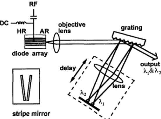
Figure 1 shows the laser configuration. A gain-guided 10-stripe phase-locked laser array (Spectra
Diode Laboratories SDL-2419C, A = 0.8 /um) was
used as the gain medium. It has a high-reflectivity coating (reflectivity R > 95%) on the rear facet and an antireflection coating of =0.1% reflectivity on the front facet. Light emitted by the diode array was collimated and incident at the grazing angle upon a grating (1800 lines/mm). The first-order diffracted light was then focused by a lens (f = 150 mm) on a V-shaped double-stripe end mirror. The zeroth-order diffraction from the grating, which was 790 with respect to the normal of the grating, was the output of the laser. The two-wavelength output (Al and A2) was coaxial, and the wavelength separation
was determined by the V-shaped double-stripe end mirror. The grating-lens-stripe-mirror combination was just a folded dispersive delay line or a grating-pair compressor with an internal telescope. We var-ied the dispersion of the external cavity by adjusting the distance between the lens and the grating while keeping constant the distance (150 mm) between the lens and the stripe mirror. Thus optimization of the separation of the lens-mirror combination and the grating resulted in compensation of linear chirp in the cavity.6 The threshold bias current of the laser was 240 mA.
The inset of Figure 1 is a schematic of the V-shaped double-stripe end mirror. The V-V-shaped double-striped end mirror was used to select simul-taneously the two output wavelengths. The length of each stripe was 15 mm. The angle between the two stripes was - 150. The width of each stripe
was 0.167 mm, corresponding to an equivalent spec-tral filter with a bandwidth of 0.27 nm, which is just smaller than the mode spacing of the diode chip. We could tune the spectral separation of the two output wavelengths from 2 to 11 nm by vertically translat-ing the double-stripe end mirror with respect to the optical axis. The corresponding spacing of the two stripe mirrors was 1.2-6.6 mm. The reported
maxi-RF
1
DC objective grating diode array'I
stripe mirror /Fig. 1. Laser configuration: HR, high reflection; AR, antireflection. The inset shows a schematic of the V-shaped double-stripe mirror.
September 15, 1994 / Vol. 19, No. 18 / OPTICS LETTERS 1457
It is a sinusoidal function with a period of 0.072 mm. This corresponds to half a period of a synthetic wave-length, A = A1A2/IA, - A21, at a spectral separation
of 4.44 nm. That is, these are interference fringes that are due to the two-color pulses.
1.0
wavelength (nm)
Fig. 2. Spectrum of the two-wavelength laser output for a spectral separation of 4.44 nm
mum spectral separation can be increased somewhat by the injection of a higher dc bias current or the use of a laser-diode structure with an intrinsically higher
bandwidth. The laser was actively mode locked by
simultaneous injection of a rf sinusoidal modulation
signal as high as 1 W at a frequency of 313 MHz
and a dc bias current of 180 mA through a bias tee. A monochromator and a noncollinear autocorrelator
were used to measure the output spectrum and pulse width. The zeroth-order reflections from the grat-ing-of light at the two wavelengths retroreflected from the end mirror-were angularly separated and served as a useful auxiliary output for monitoring the two resonant wavelengths and the timing jit-ter of each wavelength separately. We used both the time-domain cross-correlation and the frequency-domain technique7'8 for timing jitter measurements. For the latter technique a high-speed photodetector (Antel ps-s2) and a rf spectrum analyzer (HP 8568B,
with a resolution bandwidth of 10 Hz) were used to
measure the single-sideband phase noise level rela-tive to the carrier per 1-Hz bandwidth.
Figure 2 shows the two-color output spectrum at 804.20 and 799.76 nm. The average output power
of each wavelength was 4 mW. The side-mode sup-pression ratio was found to be better than 20 dB for
each wavelength. The full width at half-maximum of the output spectrum at each wavelength was
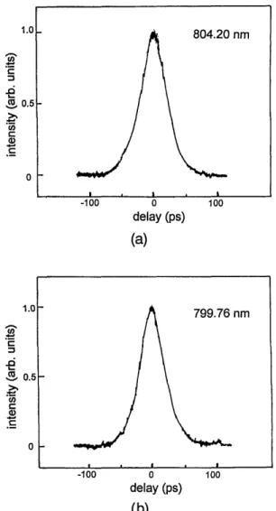
- 0.13 nm. The autocorrelation traces of the pulses
of each wavelength are shown in Fig. 3. We recorded these by blocking one of the stripe mirrors. It was found that the correlation traces could be fitted best by a sech2 function. The shortest deconvoluted pulse width was 29 ps for each wavelength at the optimized compression condition, which corresponded to an in-tracavity dispersion of -0.017 ps/nm.9
Figure 4 shows an autocorrelation trace of the dual-wavelength output with both stripe mirrors
un-blocked. This curve corresponds to a double cross
correlation since the two-color pulses were simulta-neously sent into each arm of the correlator. The deconvoluted pulse width was also 29 ps, the same
as that for each wavelength. The measurement
ac-curacy of our autocorrelator was better than a few femtoseconds. These results indicate that the jitter between the two pulses of each wavelength was of
the order of or less than 1 ps. The inset of Fig. 4
shows the magnified view at the peak of the double cross-correlation trace as a function of delay distance.
. 0) a co a) C2 II) 0.5 0 804.20 nm I \ l L -100 0 100 delay (ps)
(a)
1.01-. Cot ._ 0) Is C: 0.5H 0 -100 0 delay (ps) (b) Fig. 3. Autocorrelation traces of two-color laser at wavelengths of 799.76 nm. 1.0 CO ax .d ._5the output of the (a) 804.2 and (b)
0.5
F-0
-100 0
delay (ps)
Fig. 4. Double cross-correlation trace of the synchro-nized two-color pulses. The inset show the magnified view at the peak of the double cross-correlation trace. 0 ~-2 .j! -20 c ._ C -40 799.76 nm 100 -0.2 0 0.2 delay (mm) 100
1458 OPTICS LETTERS / Vol. 19, No. 18 / September 15, 1994 0 -20 -40 -60 -80 - wavelength = 799.76 nm| -- -wavelength = 804.2 nm
10o 10 lo, 10o
offset frequency (Hz)
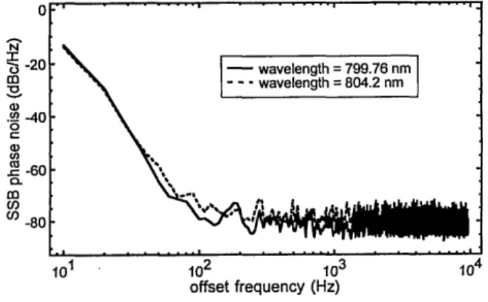
Fig. 5. Single-sideband (SSB) phase noise two-color laser output at 799.76 and 804.2 nm.
of the
Figure 5 shows the single-sideband phase noise at the fourth harmonic (4 x 313 MHz) of the two-color output at 804.2 and 799.76 nm. By use of standard frequency-domain techniques7,8 the abso-lute rms timing jitters of the two-color outputs at
804.2 and 799.76 nm were calculated from Fig. 5 to be 870 and 550 fs (100 Hz to 10 kHz), respectively.
In comparison, the absolute timing jitter of an ac-tively mode-locked single-stripe laser diode in an ex-ternal cavity was 240 fs.5
In conclusion, we have demonstrated a new con-figuration for an actively mode-locked laser-diode array capable of generating tunable synchronized dual-wavelength picosecond pulses. The key ele-ment is an intracavity folded dispersive delay line with a V-shaped double-stripe mirror. The shortest
pulse width of each wavelength was 29 ps after opti-mization of the intracavity dispersion. The spectral separation between the two wavelengths could be conveniently tuned from 2 to 11 nm by translation of the V-shaped mirror vertically. Interference fringes observed in the trace of the double cross correla-tion of the collinear dual-wavelength output have been identified.
C.-L. Wang acknowledges the assistance of Jia-Min Shieh and Gong-Ru Lin. This study was partially
supported by the National Science Council of the
Re-public of China under grant NSC83-0618-E009-007.
References
1. C.-L. Wang and C.-L. Pan, Appl. Phys. Lett. 64, 3089 (1994).
2. M. R. X. de Barros and P. C. Becker, Opt. Lett. 18,631 (1993).
3. D. R. Dykaar and S. B. Darack, Opt. Lett. 18, 634 (1993).
4. J. M. Evans, D. E. Spence, D. Burns, and W. Sibbett, Opt. Lett. 18, 1074 (1993).
5. Z. Zhang and T. Yagi, Opt. Lett. 18,2126 (1993). 6. C.-L. Wang and C.-L. Pan, "Tunable picosecond pulse
generation from an actively mode-locked laser diode array with intracavity chirp compensation," submitted to Opt. Lett.
7. D. J. Derickson, A. Mar, and J. E. Bowers, Electron. Lett. 26, 2026 (1990).
8. D. J. Derickson, P. A. Morton, J. E. Bowers, and R. L. Thornton, Appl. Phys. Lett. 59, 3372 (1991).
9. 0. E. Martinez, IEEE J. Quantum Electron. QE-23, 59 (1987). ,uZ N C) m -Dn .n 0 U, Ca 0. 0) 0)