The influence of surface ruptures on building damage in the 1999
Chi-Chi earthquake: a case study in Fengyuan City
J.J. Dong
a,*, C.D. Wang
b, C.T. Lee
a, J.J. Liao
c, Y.W. Pan
c aInstitute of Applied Geology, National Central University, No. 300, Jungda Road, Jungli City, Taoyuan 320, Taiwan, ROC b
Department of Civil Engineering, Nanya Institute of Technology, Jungli, Taiwan, ROC c
Department of Civil Engineering and Hazard Mitigation Research Center, National Chiao-Tung University, Hsinchu, Taiwan, ROC
Abstract
In addition to the main surface rupture along the Chelungpu fault associated with the 1999 Chi-Chi, Taiwan earthquake, numerous secondary or branch ruptures on hangingwall were also observed. These secondary surface ruptures are parallel or sub-parallel to the main rupture within a distance of a few meters to 1 – 2 km. The rupture length of these secondary ruptures varies from a few tens of meters up to 5 km. The surface deformation resulted in serious damages of buildings. The present work studied the features of surface deformation on the hangingwall around the Chung-Cheng Park, Fengyuan, Taichung. Three distinct surface ruptures, minor ruptures and tension cracks were observed in this area. The observed distribution and types of building damage on the hangingwall are demonstrated. Due to the difference in geological condition and complex pattern of surface deformation, the resulted building damages on the hangingwall vary.
A series of site investigation including field survey, drilling, seismic prospecting, P – S logging tests and laboratory tests were carried out in the interested area. A geological structure model was proposed on the basis of the results of site investigation. Numerical simulation was carried out to model the surface deformation as well as subsurface potential damage zone of an active fault. It reasonably explains the observed pattern of surface deformation and indicates that the surface deformation zone during a catastrophic earthquake is predictable.
D 2003 Elsevier Science B.V. All rights reserved. Keywords: Hangingwall; Building damage; Chi-Chi earthquake
1. Introduction
The 1999 Chi-Chi earthquake (Mw7.6) resulted in
more than 2000 casualties and numerous damages in various structures and buildings. Among many dam-ages of buildings, lots of them are due to the
in-fluence of surface ruptures associated with the catastrophic earthquake. The surface ruptures include main surface rupture, as well as secondary or branch ruptures which were observed on the hangingwall, within a few meters to 1 – 2 km, and parallel or sub-parallel to the main rupture. The rupture length of these secondary ruptures varies from a few tens of meters up to 5 km. Bonilla (1970) found that dis-placement on secondary fractures could be as much as 20% that on the main fault even if they are 12 km away. Hence, the potential for the displacement of 0013-7952/$ - see front matterD 2003 Elsevier Science B.V. All rights reserved.
doi:10.1016/S0013-7952(03)00131-5
* Corresponding author. Tel.: 4224114; fax: +886-3-4263127.
E-mail address: [email protected] (J.J. Dong).
www.elsevier.com/locate/enggeo Engineering Geology 71 (2003) 157 – 179
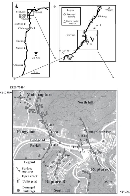
Fig. 1. The surface ruptures (uplift is illustrated as U560, in cm) and distribution of damaged buildings in Chi-Chi earthquake (redrawn from NCREE, 2000).
J.J. Dong et al. / Engineering Geology 71 (2003) 157–179 158
secondary fractures on inactive faults, bedding planes or existing fractures should not be ignored (Bray et al., 1994a).
The deformation features are complex on the hang-ingwall of the Chelungpu fault. Lee et al. (2000)
categorized the deformation styles on the hangingwall as nine different classes according to the surface fault-ing, warpfault-ing, tiltfault-ing, bending and backthrusting near the Chelungpu fault. The surface deformations resulted in serious building damages, especially on the build-ings adjacent to the surface ruptures on the hanging-wall. Avoidance of fault-rupture hazards should account for the pattern of surface deformation(Kelson et al., 2001).
The present work studies the relation between surface deformation on the hangingwall and distribu-tion of damaged buildings. Cases near the area of the Chung-Cheng Park, Fengyuan, Taichung, were inves-tigated. The band-width of surface deformation on the hangingwall was about 300 m. Typical pattern of surface deformation containing thrusting with back-thrust development was observed (Lee et al., 2000; Kelson et al., 2001). A series of site investigation including seismic prospecting, borehole exploration, P – S logging tests and laboratory tests were carried out. A geological structure model has been proposed according to the site investigation. The induced defor-mation pattern on the hangingwall in the Chi-Chi earthquake is simulated then compared with the meas-ured data.
So far, approaches by physical, analytical and numerical models have been attempted to study the
problems of fault propagation (e.g., Scott and Schoustra, 1974; Sherard et al., 1974; Seed, 1979; Roth et al., 1981; Billings, 1985; Cole and Lade, 1984; Lade et al., 1984; Bray et al., 1994a,b; Vallejo
and Shettima, 1996; Nino et al., 1998). Numerical
simulation, such as using FEM, seems promising for studying the complex mechanical behaviors of thrust faults (Nino et al., 1998). Solving large strain geo-dynamical problems has been attempted based on viscous-plastic, elasto-plastic, rheology models under quasi-static conditions. Faults are identified as regions in which concentrated and localized large strains had occurred. This work uses a commercial finite difference code FLAC to model the surface deformation on the hangingwall induced by fault movements through rock. The numerical simulation can reasonably explain the observed pattern of sur-face deformation.
2. General features of surface ruptures and distribution of damaged buildings near the Chung-Cheng Park
The Chi-Chi earthquake is resulted from the slip of the Chelungpu fault which is a thrust fault. The total length of the surface rupture associated with the Chi-Chi earthquake is about 96 km. As shown in Fig. 1, the rupture surface extends from Chushan to gyuan along a nearly N – S trend. Starting at Fen-gyuan, the subsequent rupture surface, named Shihkang – Shangchi segment (SSS), rotates
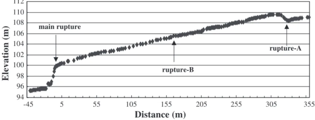
clock-Fig. 2. The measured profile of surface deformation along the valley near the Chung-Cheng Park after Chi-Chi earthquake (redrawn fromLee et al., 2000).
wise almost 90j into E – W trend. The length of the SSS is about 15 km. Pop-up structure bounded by thrust and backthrust are characterizing the SSS. The complex patterns of surface rupture and related mech-anisms of this fault zone were discussed thoroughly byLee et al. (2002). Relatively, the patterns and the mechanisms of surface rupture from Chushan to Fengyuan have been well understood.
The Chung-Cheng Park is located in the east Fengyuan (a town located in the north Taichung).
The studied area is between N24.2513j, E120.7426j and N24.2599j, E120.7349j. Some interesting phe-nomena of surface deformation were observed on the hangingwall of the Chelungpu fault near the Chung-Cheng Park. The main rupture in this area appears to be a thrust with a slight left-lateral component. The vertical uplift of the main rupture is 4 – 5 m. The averaged vertical uplift is only about 2 – 3 m in the southern segment of the Chelungpu fault. En echelon distributed open cracks and distinct secondary rup-Fig. 3. Main fault near Park No. 1 Bridge. At ruptures along foot of the hill and appears to be a thrust with a slight left-lateral component. The vertical uplift is 4 – 5 m and the apparent horizontal separation is 7 m.
Fig. 4. The wavy road surface due to hangingwall deformation near the Chung-Cheng Park. J.J. Dong et al. / Engineering Geology 71 (2003) 157–179
Fig. 5. Rupture-A in the Chung-Cheng Park. The left side of this photo faces west. The vertical uplift is 0.9 m.
Fig. 6. Rupture-B near the Chung-Cheng park. Rupture-B lies between the main rupture and rupture-A. The vertical uplift of the surface rupture is 0.1 – 0.2 m. The east side of the surface rupture is higher than the west side.
tures are commonly presented on the hangingwall. The vertical uplift of the most important secondary rupture is about 0.9 – 1.8 m, close toBonilla’s (1970)
observation. The width of influenced band including the main and secondary surface ruptures is about 300 m.
Fig. 1 shows the topography and surface ruptures
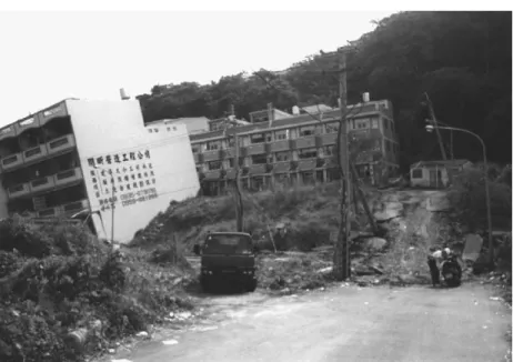
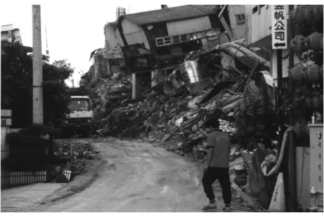
near the Chung-Cheng Park area. It is located at the center of the studied area, and on the north hill of a valley. A village stands on the south hill of the valley. Three surface ruptures are noticeable in Fig. 1, they are (1) main rupture (main fault) and (2) Fig. 7. Buildings damaged by the main rupture near the Chung-Cheng Park (1).
Fig. 8. The buildings damaged by the main rupture near the Chung-Cheng Park (2). The main rupture extends along foot of the hill. J.J. Dong et al. / Engineering Geology 71 (2003) 157–179
secondary ruptures (rupture-A and rupture-B). Minor surface ruptures and open cracks are also observed. The measured profile after the Chi-Chi earthquake along the valley is shown inFig. 2 (Lee et al., 2000).
Lee et al. (2000) interpreted the deformation pattern
as thrusting with backthrust development. The meas-ured uplifts of main and secondary ruptures by Lee
et al. (2000) are marked in Fig. 1. The
charac-teristics of these surface ruptures are discussed as follows.
Fig. 9. Buildings damaged by the main rupture near the Chung-Cheng Park (3).
Fig. 10. Buildings damaged by the main rupture near the Chung-Cheng Park (4).
2.1. Main surface rupture
The strike of the main surface rupture is N – S in the south of the studied area (Fig. 1). It turns to N45jE near the Chung-Cheng Park and turns again to N30jW abruptly to the north of the Park No.1 Bridge, making a ‘‘V’’ shaped pattern which convex to the east(Fig. 1). The surface rupture is along foot of the hill in the west of the studied area. Near Park No.1 Bridge, the vertical uplift is about 4 – 5 m, and the apparent horizontal separation is 7 m (Fig. 3). About 400 m away from the north end of Park No.1 Bridge, the strike of the surface rupture turns again
into N30j – 45jE and extended 3 km further to Shihkang.
2.2. Secondary surface rupture
Secondary surface ruptures and cracks occurred in the studied area locate well on the hangingwall of the main fault. Besides those secondary fracture and cracks, ground surface is also deformed. The asphaltic road surface on the hangingwall near the Chung-Cheng Park shows wavy appearance (Fig. 4). Two distinct secondary ruptures are discussed subsequently.
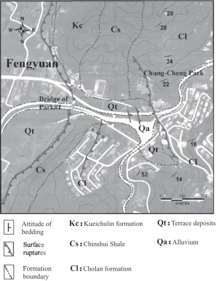
Fig. 11. Geological map in the vicinity of the Chung-Cheng Park. J.J. Dong et al. / Engineering Geology 71 (2003) 157–179 164
2.2.1. Rupture-A
Rupture-A is the most important secondary surface rupture near the Chung-Cheng Park. It is on the east of the main rupture. The distance between the surface rupture of rupture-A and the main rupture is about 300 m. The length of this surface rupture is about 350 m. The strike of this surface rupture is N10jW. The vertical uplift of the surface rupture is 0.9 – 1.8 m. The east side of the surface rupture is lower than the west side(Fig. 5).
2.2.2. Rupture-B
Rupture-B lies between the main rupture and rupture-A. The distance between the rupture-B and the main rupture is about 100 m. The length of this surface rupture is about 250 m. The strike of this surface rupture is N12jE. The vertical uplift of the
surface rupture is 0.1 – 0.2 m. Contrast to the rupture-A, the east side of the surface rupture is higher than the west side(Fig. 6).
2.3. Distribution of damaged buildings near the Chung-Cheng Park
Numerous buildings are damaged in the Chi-Chi earthquake (NCREE, 2000). Fig. 1shows the distri-bution of the damaged buildings near the Chung-Cheng Park. Figs. 7 – 10 illustrate several examples of seriously damaged buildings along the main rup-ture. Most of the damaged buildings distributed along the main surface rupture as well as the secondary ruptures. Damaged buildings on the hangingwall were also notable. These phenomena will be further dis-cussed based on the results of subsurface
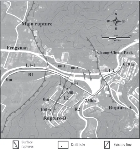
investiga-Fig. 12. Location of seismic prospecting lines and drill boreholes.
Fig. 13. Results of seismic prospecting in the valley. The lower graph shows the results of seismic refraction R1 (670 m); the upper graph shows the results of seismic reflection L1-1 (243 m) and L1-2 (138 m). The fracture zones around main rupture and rupture-A can be clearly identified.
J.J. Dong et al. / Engineering Geology 71 (2003) 157–179 166
tions and the deformation pattern on the hangingwall induced by the Chi-Chi earthquake near the site.
3. Subsurface investigations near the Chung-Cheng Park
3.1. Geological conditions
Most part of the Chelungpu fault slips along the base of Pliocene Chinshui Shale and thrusted over Holocene alluvium. However, the fault breaks into the upper-Miocene to lower-Pliocene Kueichulin formation in the northern segment near the study area. Fig. 11 shows the geological map in the vicinity of the Chung-Cheng Park. The Chinshui Shale is composed of 150 – 200 m of shale or mudstone. It is conformably overlain by the Plio-cene Cholan Formation and underlain by the Kuei-chulin formation. The Chinshui Shale appears on the hangingwall in the southern hill of Park No.1 Bridge. The Kueichulin formation, overlain by Chinshui Shale and Cholan formation, outcrop in the northern hill. The strike of bedding plane lies within N10j – 80jE and the dip is within 18j – 52j to southeast near the concerned area.
3.2. Seismic prospecting
Seismic refraction and seismic reflection methods were carried out to investigate the fracture zone due to
fault movement. The seismic prospecting uses a 24-channel McSeis170 f system (OYO company) and McSeis-111 geophones (with natural frequency 28 Hz and sensitivity 0.285 V/kine).
Two areas, as shown in Fig. 12, one in the valley (R1, L1-1, L1-2) and the other in the village up in the southern hill (R2, L2), were investigated. Fig. 13
shows the results of seismic prospecting in the valley. In this figure, the lower graph is the results of seismic refraction along R1 (670 m) and the upper one is the results of seismic reflection along L1-1 (243 m) and L1-2 (138 m). Fig. 14 shows the results of seismic refraction along R-2 (230 m) in the southern hill.Fig. 15 shows the results of seismic reflection along L-2 (102 m).
Three faults are identified from the results of seismic reflection (Figs. 13 and 15). The fracture zones around the main rupture and rupture-A under the ground surface can be clearly identified inFig. 13
(fracture zone around the main fault on the left side; fracture zone around rupture-A on the right side). There are more than one strong reflection can be observed in Fig. 13 around both fracture zones. It indicates that fracture zones are formed rather than a single slip surface. Fracture zone around rupture-B across the uphill village is also noticeable inFig. 15. As a minor surface rupture, the fracture zone around rupture-B is not as obvious as the fracture zones around the main rupture and rupture-A.
According to the results of seismic refraction(Fig. 13), the depth of the alluvium is about 5 – 20 m in the
Fig. 14. Results of seismic refraction R-2 (230 m long) in the south hill. The band of low velocity indicates the fracture zone around rupture-B across the village.
valley. The primary wave velocity Vp ranges from
0.29 to 1.09 km/s. The zones of P-wave low veloc-ities, indicating a fracture zone or weak rock, are also shown in Figs. 13 and 14. Two distinct areas are
identified: (1) the primary wave velocity of a fracture zone, disturbed zone or weak rock, ranges from 1.58 to 2.1 km/s; and (2) the primary wave velocity of a relative competent rock ranges form 2.25 to 2.54 km/
Fig. 16. Zones of P-wave low velocities near surface ruptures.
Fig. 15. Results of seismic reflection L-2 (102 m) in the south hill. The black line marks the fracture zone around rupture-B across the village. J.J. Dong et al. / Engineering Geology 71 (2003) 157–179
s. There are two distinct areas bisected inFig. 16. The zones of P-wave low velocities are around the surface rupture. The widths of the zones of P-wave low velocities are nearly 90 – 100 m around the main rupture and rupture-A. The width of the zone of P-wave low velocities in the hangingwall is about 70 m. It appears that the fracture zone is wider in the
hangingwall than in the footwall. The width of the zone of P-wave low velocities is relatively narrow around rupture-B, only about 10 – 15 m.
3.3. Core drilling, P – S logging and laboratory tests Three boreholes, each 20 m deep, were conducted on the village on southern uphill as shown inFig. 12. The thickness of residual soil is about 0.2 – 1.2 m. The underlying rock mass is composed of sandstone and siltstone/sandstone. The averaged RQD for core of BH-1, BH-2 and BH-3 are 90%, 85% and 60%, respectively. The unconfined compression strength qu for intact rock is in the range of 2.0 – 18.3 MPa.
The averaged unit weight of rock samples is 25 kN/ m3.Table 1 lists the engineering properties for cored samples from three boreholes.
Suspension P – S logging tests were conducted in boreholes for obtaining the profile of body-wave and shear-wave velocities, denoted as Vp and Vs, for the
rock mass underlying the case site. The test made Table 1
The engineering properties for cored samples from three boreholes Rock type Averaged
RQD(%) qu(MPa) Density (kN/m3) BH-1 Siltstone/ sandstone 90 2.0 (18 ma) 2.44 (18 ma) BH-2 Siltstone/ 85 4.8 (9 ma) 2.46 (9 ma) sandstone (0 – 10 m) 18.3 (11 ma) 2.54 (11 ma) Sandstone 14.4 (12 ma) (10 – 20 m) 17.8 (17 ma) 2.53 (17 ma) BH-3 Sandstone 60 9.2 (13 ma) 2.51 (13 ma) 12.8 (14 ma) a
Core depth measured from the ground surface.
Fig. 17. Primary-wave and shear-wave velocity distributions in BH-2 from P – S logging test.
use of the OYO suspension P – S logging instru-ments. The averaged Vp for 1, 2 and
BH-3, respectively, are 1.55, 2.52 and 1.59 km/s. The
averaged Vsobtained from P – S logging test in BH-2
is 1.24 km/s. Fig. 17 presents the measured body-wave and shear-body-wave velocity in BH-2. However, Fig. 18. A – A cross-section and proposed two-dimensional geological model.
Fig. 19. The strong-motion records (E – W component) at TCU052. Large velocity pulses can be observed. J.J. Dong et al. / Engineering Geology 71 (2003) 157–179
the averaged Vs measured in BH-1 and BH-3,
respectively, are only 0.41 and 0.33 km/s. According toFig. 16, BH-1 and BH-3 were drilled in the zones of P-wave low velocities. The Vp obtained from the
P – S logging tests are very close to the Vpobtained
from the seismic refraction prospecting. The compar-ison indicates that the rock mass adjacent to BH-1 and BH-3 are likely fractured or disturbed. It may also indicate the rock mass is relatively competent around BH-2.
Fig. 20. Building in the center of the photo was tilted by uplifting of the hangingwall, but the structure remained intact.
Fig. 21. Building on the hangingwall is damaged while the one on footwall remains intact.
A two-dimensional geological model is proposed on the basis of the results of site investigations and the observed deformation pattern. Fig. 18 presents the cross-section of A – A which clearly identify the
rup-ture-A as a backthrust of the main fault. The rock mass adjacent to the main fault in the hangingwall was heavily stressed which very likely resulted in the secondary surface ruptures and cracks. Among several Fig. 22. Distribution of damaged buildings in the Chi-Chi earthquake near the Chung-Cheng Park (redrawn fromNCREE, 2000).
Fig. 23. Buildings in the uphill of village where rupture-B passed through were severely damaged. J.J. Dong et al. / Engineering Geology 71 (2003) 157–179
minor surface ruptures, the rupture-B is the most important one. A relative competent rock mass exists between rupture-A and rupture-B.
4. The geometry of ruptures and induced building damages near the Chung-Cheng Park
Near the faulting area, the buildings are seriously damaged. The near-fault effect, including static ‘‘fling step,’’ and dynamic ‘‘directivity pulse’’, of strong ground motion and surface deformation may play the major role. Besides, it is observed that more buildings are damaged on the hangingwall compared with the buildings on the footwall. The phenomena can be attributed to the hangingwall effect of strong ground motion (Abrahamson and Somerville, 1996; Allen et al., 1998)and/or the complex surface defor-mation pattern on the hangingwall(Lee et al., 2000). Consequently, building damages could be induced by strong ground motion or surface deformation during an earthquake. It is indeed very difficult to separate the effects of strong ground motion and surface ruptures on building damages. The characteristics of the near-fault ground motions and hangingwall effects and the surface-rupture related building damage are discussed in the following context.
4.1. Hangingwall effects and near-fault effects of strong ground motion
Numerous records of strong ground motion in the Chi-Chi earthquake are available. The nearest strong-motion stations to the case area (as shown inFig. 1) are TCU101, TCU102 (in Fengyuan) on the footwall and TCU068, TCU052 (in Shihkang and Taichung, respectively) on the hangingwall. The distances between the studied area and stations TCU068 and TCU052 are about 4 – 5 km. Four stations are very close to the main fault. The horizontal components of PGA in TCU101 and TCU102, respectively, on the footwall are 0.26g and 0.30g. The horizontal components of PGA in TCU068 and TCU052, respectively, on the hangingwall are 0.51g and 0.45g. A phenomenon of higher peak accelerations on the hangingwall than on the footwall is observed. This hangingwall effect of strong ground motion generally exists near the studied area. Miyakoshi
and Hayashi (2000) investigated the damage rate
around the strong-motion stations. The PGA was double on the hangingwall (TCU068, 052) compar-ing to the PGA on the footwall (TCU101, 102); however, the damage rate was below 5% adjacent to the four stations in the studied area(Midorikawa and Fujimoto, 2000).
Large velocity pulses, which may cause from the directivity and fling effects, were recorded at the stations TCU052 (Fig. 19)during the Chi-Chi earth-quake.Somerville (2000)found the directivity effects were minor at stations TCU052 and TCU068 compar-ing to the static ground displacement and plastic
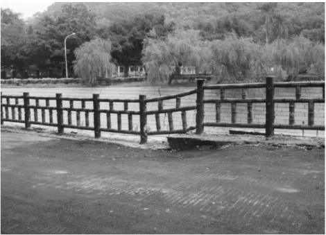
Fig. 24. Roadway and barricade are broken due to rupture-B. A building on the uphill is tilted due to ground deformation. J.J. Dong et al. / Engineering Geology 71 (2003) 157–179 173
deformation of the hangingwall. The period of the rupture directivity pulse increases with the earthquake magnitude. The period of the directivity pulse recorded at Tsaotun during the Chi-Chi earthquake is about 4 s. Since all the buildings near the case area are under five stories, the rupture directivity effects should not dominate the building damages. The period of fling is longer than the directivity. It is not yet known which types of structures are more sensitive to fling. Nevertheless, it appears that the long period
fling pulse should not dominate the damage of a common five-storied building.
4.2. Surface ruptures and induced building damages As shown in Fig. 1, most of the damaged build-ings in the studied area distribute along the main surface rupture as well as the secondary surface ruptures on the hangingwall. The main surface rup-ture damages most of its adjacent buildings near the Chung-Cheng Park. The main rupture, with a 4 – 5 m uplift on the hangingwall, damage nearby buildings. A building astride the main-rupture is seriously titled as shown in Fig. 20. Nevertheless, the structure remains intact. Fig. 21 shows that the building on the hangingwall is damaged while the one on foot-wall remains intact. The influence of ground defor-mation on structure’s survivability is obvious. The effect of surface deformation on hangingwall near Table 2
Material parameters used in numerical model
Material type Shear
modulus (GPa) Poisson’s ratio Relative competent rock mass 3.67 0.33 Fractured or disturbed zone 0.35 0.46
Fig. 25. Interface elements in the model. J.J. Dong et al. / Engineering Geology 71 (2003) 157–179 174
the Chung-Cheng Park to building damage is further explored.
Fig. 22 shows the buildings on hangingwall near
the Chung-Cheng Park are damaged to various extents. Five buildings in the valley distributed to the east of rupture-A are lightly to moderately damaged as shown in Fig. 22 (the vertical uplift is about 0.9 – 1.8 m). Buildings in the uphill of village astride of rupture-B (the vertical uplift is about 10 cm) are also severely damaged as shown in Fig. 22. In this region, 11 buildings are damaged to various extents. Among them, two of them are seriously tilted. Between rupture-A and rupture-B, there are also 11 damaged buildings. Five of them are titled or severely damaged. There are a few minor secondary surface ruptures to the north of these buildings. The effect of surface deformation on hangingwall appears evident on the buildings’ damage. FromFig. 22, the following phenomena are noted.
4.2.1. Most damaged buildings distribute in zones of P-wave low velocities
Comparing Figs. 1, 16 and 22, it is found that many damaged building in the studied area are located in zones of P-wave low velocities. On hangingwall of a thrust fault, it is always with potential that certain displacement of a secondary fracture may take place in a relatively weak zone. Hence, the zones of P-wave low velocities near the thrust and backthrust may be considered as a good reference to regulation development adjacent to an active fault.
The region between rupture-A and rupture-B is not considered as a zone of P-wave low velocity; also, the observed surface ruptures in this region are insignificant. Rock mass in this region should not be very fractured. However, there are 11 damaged buildings in the region. Thus, the observed distribu-tion of damaged buildings on the hangingwall is not solely arisen from the presence of fracture zone alone.
4.2.2. Some buildings are damaged by minor surface rupture
The rupture-B is a minor surface rupture (the vertical uplift is only about 10 cm) comparing to the main rupture and rupture-A. Yet, some buildings are damaged seriously. The photograph shown inFig. 23
illustrates structure damages caused by surface rupture of rupture-B. The roadway and barricade are also broken due to the rupture (Fig. 24).
Comparing to the large uplifts observed along the main rupture, the differential deformation is small near rupture-B. The residual soil on uphill of village is very thin (0.2 – 1.2 m). It is suspected that the abrupt differential deformation due to the direct thrust from the underlying rock mass explains the damage of buildings astride rupture-B. The 11 dam-aged buildings between rupture-A and rupture-B are located to the south of two minor surface ruptures. Surface rupture is a possible factor for the building damages.
Fig. 26. Logics of numerical simulation.
4.2.3. Effect of foundation type on a building’s survivability
The differential settlement of single footings resulted in shear crack and damaged the structure seriously as shown in Fig. 23. The building in Fig. 23would have survived if a mat foundation had been used. Structures of many buildings astride the main rupture (which raised 4 – 5 m) remain intact (but tilted)
(Fig. 20). The survivability of a building during
earthquake surface rupturing depends on its founda-tion type.
4.2.4. Surface deformation without rupture can also damage a building
A five-storied building up the hill shown in Fig. 24 is tilted due to ground deformation and without surface rupture. The structure is still in function but the maximum rotation is about 1/50. The maximum rotation is toward east, consistent with the
kine-matics of wedge motion according to the geological model.
5. Numerical simulation
The forgoing context demonstrates that the geo-logical condition and surface deformation pattern, especially the surface ruptures, are crucial to evaluate the building damages. An attempt was made to simulate the surface deformation with specified prop-erties in the proposed geological model. Instead of evaluating rupture mechanism, the purpose of the simulation is to demonstrate the possibility of cor-rectly predicting surface deformation based on the results of detailed site investigation. This work made use of a commercial finite difference code FLAC to model the surface deformation induced by fault move-ments through rock. FLAC has been widely used in
Fig. 27. The simulated displacement field. J.J. Dong et al. / Engineering Geology 71 (2003) 157–179 176
geo-mechanics. Its element library provides interface element capable of modelling the planes on which sliding or separation may occur. The effect of over-lying soil is ignored. The simulated results will be compared with the recorded deformation data.
Chang (2000)made use of FLAC to simulate the
active structure of the Chelungpu fault by interface elements. He conducted a series of parametric study on various parameters’ effects on slip displacement.
Chou and Ke (2001) also performed a sensitivity
analysis on the rupturing behaviour of an overlying soil layer due to fault movement using FLAC. In their study, the surface displacement due to fault movement of underlying normal and reverse faults of various dip angles was evaluated. However, the existence of accompanied branch faults was not taken into account in numerical simulation.
Numerical simulation by FLAC was carried out to simulate the surface deformation along with fault
movements. The overall mesh dimension is 600 m wide and 250 m deep. The mesh contains two types of elastic materials: relative competent rock mass and fractured/disturbed zone; they were divided accord-ing to the cross-section shown in Fig. 18. Table 2
lists the input shear moduli and Poisson’s ratios in the model, they were calculated from the averaged Vp and Vs obtained from P – S logging tests. The
shear modulus of the relative competent rock mass, obtained from the average wave-velocities of BH-2, is 3.67 GPa. The shear modulus of the fractured or disturbed zone, obtained from the average wave-velocities of BH-1 and BH-3, is 0.35 GPa. The Poisson’s ratios for the relative competent rock mass and for the fractured or disturbed zone, respectively, are 0.33 and 0.46. In the model, the bottom boun-dary was fixed in the vertical direction; the vertical boundaries were fixed in both directions. The inter-face set in the model as depicted in Fig. 25
repre-Fig. 28. The contours of the calculated principal stress ratio (r1/r3).
sents the Chinshui Shale. When the interface is declared glued, no slip or opening is allowed, only elastic displacement can occur. Fig. 26 presents the logic of the numerical simulation. Boundary displace-ment rate of 3 cm/year was applied to the vertical boundary to model the plate motion; the displacement rate was chosen to represent the approximate relative horizontal motion along the whole length of the Longitudinal Valley Fault (LVF), which is generally regarded as the suture zone of the Taiwan collision
(Yu et al., 1997).
Fig. 27 presents the displacement for the results
of the numerical simulation. The maximum displace-ment occurred in the vicinity of surface rupture of the main fault in the hangingwall; the maximum displacement is about 5 m. The displacement grad-ually decreases to 0.7 m near the location of the backthrust (rupture-A). The trend of calculated defor-mation pattern is in accordance with the recorded apparent displacement on the ruptures.Fig. 28shows the contour of the principal stress ratio (r1/r3). Two
main bands of stress concentration are notable inFig. 28. Some thin tensile zones are also observed. Heavy stress concentration usually results in rock fracture; hence, the bands of stress concentration may imply the locations of fractures and faults. As a matter of fact, the bands of stress concentration from the simulation appear consistent with the fractured zones observed from seismic tests. It seems that the pre-sented numerical is possible for modeling the poten-tial zones of active faults and its induced surface deformation as long as the input parameters are correctly estimated. Nevertheless, a correct geolog-ical model is essential for accurately evaluating the surface deformation. Hence, thorough subsurface investigation is a prerequisite for this goal.
6. Summary and conclusions
A case study of the relation between surface deformation on hangingwall and distribution of dam-aged buildings in the Chi-Chi earthquake has been carried out. The surface deformation on hangingwall resulted in the damages of buildings near the main rupture as well as the minor surface ruptures. It appeared that the effect of surface deformation on building damage played a major role since the
hang-ingwall effect of strong ground motion and near-field effect on building damage were not obvious. It is hence concluded that the geological condition and surface-deformation pattern, especially the surface ruptures, are crucial to evaluate the building damages on hangingwall. Nevertheless, foundation type also made a large difference in the building’s survivability subjected to surface rupture and deformation during a catastrophic earthquake.
A two-dimensional geological model is proposed according to the results of site investigations and the observed deformation pattern. An attempt was made to simulate the surface deformation with specified properties according to the proposed geological model. The numerical simulation reasonably explains the observed pattern of surface deformation. The simulated results also show the possibility for the evaluation of the subsurface potential damage zone of an active fault. It demonstrates the possibility of predicting surface deformation based on the results of detailed site investigation. From the presented inves-tigation, it appears that the zones of P-wave low velocities may serve as an indication of a potentially damage-prone zone in a future earthquake event. Thus, the region of P-wave low velocities near the thrust and backthrust may be considered as a reference to regu-lation development adjacent to an active fault. References
Abrahamson, N.A., Somerville, P.G., 1996. Effects of the hanging wall and footwall on ground motions recorded during the North-ridge earthquake. Bulletin of Seismological Society of America 86, 593 – 599.
Allen, C.R., Brune, J.N., Cluff, L.S., Barrows Jr., A.G., 1998. Evi-dence for unusually strong near-field ground motion on the hangingwall of the San Fernando fault during the 1971 earth-quake. Seismological Research Letters 69 (6), 524 – 531. Billings, H.J., 1985. Hydraulic fill dams made earthquake resistant.
Civ. Eng. Am. Soc. Civ. Eng., New York, June, 55 – 59. Bonilla, M.G., 1970. Surface faulting and related effects. In:
Wei-gel, R.L. (Ed.), Earthquake Engineering. Prentice-Hall, Engle-wood Cliffs, NJ, pp. 47 – 74.
Bray, J.D., Seed, R.B., Cluff, L.S., Seed, H.B., 1994a. Earthquake fault rupture propagations through soil. Journal of Geotechnical Engineering 120, 543 – 561.
Bray, J.D., Seed, R.B., Seed, H.B., 1994b. Analysis of earthquake fault rupture propagation through cohesive soil. Journal of Geo-technical Engineering 120, 562 – 580.
Chang, J.Y., 2000. Numerical Modeling of Active Structures of the Chelungpu Fault. Thesis, presented to National Central Univer-J.J. Dong et al. / Engineering Geology 71 (2003) 157–179
sity, at Taiwan, Republic of China, in partial fulfillment of the requirements for the degree of Master.
Chou, H., Ke, T.C., 2001. Rupturing of an overlying soil layer due to fault movement using FLAC. Proceedings of 9th Conference on Current Researches in Geotechnical Engineering, Shihman Reservoir, Tai-Yuan, Taiwan, Republic of China, A081. Cole, D.A., Lade, P.V., 1984. Influence zones in alluvium over dip –
slip faults. Journal of Geotechnical Engineering 110, 599 – 615. Kelson, K.I., Kang, K.H., Page, W.D., Lee, C.T., Cluff, L.S., 2001. Representative styles of deformation along the Chelungpu fault from the 1999 Chi-Chi (Taiwan) earthquake: geomorphic char-acteristic and responses of man-made structures. Bulletin of the Seismological of America 91 (5), 930 – 952.
Lade, P.V., Cole, D.A., Cummings, D., 1984. Multiple failure sur-faces over dipslip faults. Journal of Geotechnical Engineering 110, 616 – 627.
Lee, C.T., Kelson, K.I., Kang, K.H., 2000. Hangingwall deforma-tion and its effect to buildings and structures as learned from the chelungpu faulting in the 1999 Chi-Chi, Taiwan earthquake. International Workshop on Annual Commemoration of Chi-Chi Earthquake, vol. I. National Center for Research on Earth-quake Engineering, Taipei, pp. 93 – 104.
Lee, J.C., Chu, H.T., Angelier, J., Chan, Y.C., Hu, J.C., Lu, C.Y., Rau, R.J., 2002. Geometry and structure of northern surface ruptures of the 1999 Mw = 7.6 Chi-Chi Taiwan earthquake: in-fluence from inherited fold belt structures. Journal of Structural Geology 24, 173 – 192.
Midorikawa, S., Fujimoto, K., 2000. Microtremor measurement at CWB strong-motion stations in the central part of Taiwan. In-ternational Workshop on Annual Commemoration of Chi-Chi Earthquake, vol. I. National Center for Research on Earthquake Engineering, Taipei, pp. 188 – 197.
NCREE, 2000. 921 Chi-Chi earthquake database analysis and man-agement system (in Chinese), National Center for Research on Earthquake Engineering, Taiwan. http://gisdb.ncree.gov.tw/ ncree/doc/.
Miyakoshi, J., Hayashi, Y., 2000. Correlation of building damage with indices of seismic ground motion intensity during the 1999 Chi-Chi, Taiwan earthquake. International Workshop on Annual Commemoration of Chi-Chi Earthquake, vol. II. National Center for Research on Earthquake Engineering, Taipei, pp. 337 – 348. Nino, F., Philip, H., Chery, J., 1998. The role of bed-parallel slip in the formation of blind thrust faults. Journal of Structural Geology 20 (5), 503 – 516.
Roth, W.H., Scott, R.F., Austin, I., 1981. Centrifuge modeling of fault propagation through alluvial soils. Geophysical Research Letters 8 (6), 561 – 564.
Scott, R.F., Schoustra, J.J., 1974. Nuclear power plant siting on deep alluvium. Journal of Geotechnical Engineering Divsion, ASCE 100 (4), 449 – 459.
Seed, H.B., 1979. Considerations in earthquake resistance design of earth and rock fill dams. Geotechnique 29 (3), 215 – 263. Sherard, J.L., Cluff, L.S., Allen, C.R., 1974. Potential active faults
in dam foundations. Geotechnique 24 (3), 367 – 428.
Somerville, P.G., 2000. Magnitude scaling of near fault ground motions. International Workshop on Annual Commemoration of Chi-Chi Earthquake, vol. I. National Center for Research on Earthquake Engineering, Taipei, pp. 59 – 70.
Vallejo, L.E., Shettima, M., 1996. Fault movement and its impact on ground deformations and engineering structures. Engineering Geology 43, 119 – 133.
Yu, S.B., Chen, H.Y., Kuo, L.C., 1997. Velocity field of GPS station in the Taiwan area. Tectonophysics 274, 41 – 59.