E L S E V I E R Surface and Coatings Tectmology 92 (i997) 197-205
,,gllRlllgE
COATINGS
HglI#OLO !
Ion nitriding of TiNi shape memory alloys I. Nitriding parameters
and microstructure characterization
S . K . W u *, C . L . C h u , H . C . L i n 1Institute of Materials Science and Engineering, National Taiwan University, Taipei 106, Taiwan Received 2 January 1997; accepted 10 March 1997
Abstract
TisoNiso and TisoNi40Culo shape memory alioys were ion nitrided to modify the surface conditions. The phases and microstructures of the nitrided surface were studied by XRD, EPMA and SEM. Experimental results indicate that the nitrided compound layer of equiatomic TiNi alloy consists of TiN and Ti2Ni phases, and that of TisoNi40Culo alloy consists of TiN, Ti2N and Ti40(Ni,Cu)60 phases. The surface hardness and the compound layer thickness increase with increasing nitriding temperature and time. These nitrided compound layers are found to exhibit a slight depression on the alloys' martensitic transformation temperatures and their shape recovery ability. A mechanism to explain the formation of the ion-nitrided layer in equiatomic TiNi alloy is also proposed in this study. © 1997 Elsevier Science S.A.
Keywords: Shape memory aIIoys; Ion nitriding; TiNi alloys
1. Introduction
TiNi alloys are known as the most important shape memory alloys (SMAs) because they exhibit thermoelas- tic martensitic transformation, and because of their many applications based on the shape memory effect (SME) [1] and pseudoelasticity (PE) [2,3]. This comes from the fact that TiNi alloys have superior properties in ductility, biocompatibility and recoverable strain. Recently, TiNi alloys have been observed to exhibit an excellent wear resistance [4=6], which is an important property in some biomedical applications, such as medi- cal guide-wires, artificial bone joints, etc. In fact, the B2 phase (austenite parent phase) of TiNi alloys can really exhibit an excellent wear resistance due to their rapid work hardening and pseudoelastic properties [7]. However, the wear resistance of B19' martensite phase of TiNi alloys is still too weak and needs to be improved for some applications. It is well known that nitriding techniques are commonly used to improve the fatigue and wear resistance of metals and alloys [8]. In particu- lar, ion nitriding has a number of advantages over conventional gas nitriding, including faster growth rates * Corresponding author.
1Present address: Department of MateriaIs Science, Feng Chia University, Taichung 400, Taiwan.
0257-8972/97/$i7.00 © 1997 Elsevier Science S.A. All fights reserved. PHSO257-8972(97)OOlOO.X
of nitrided layers, easier control over the crystal structure of nitrided layers, and fewer environmental problems [9]. Several investigations on ion nitriding have been performed for titanium and titanium alloys [10-22], but so far there have been few investigations on TiNi alloys. Only the effects of N + implantation [23] and arc ion plating [24] on TiNi alloys have been reported. In the present study, the ion nitriding of TiNi alloys is investi- gated. The nitriding parameters and the characteristics of the nitrided layers are discussed as the first part of this paper. The corrosion properties and the primary wear characteristics of the nitrided layers are discussed as the second part of this paper.
2. Experimental procedures
A conventional tungsten arc melting technique was employed to prepare the TisoNiso and TisoNi40Culo (in at.%) alloys. Titanium (purity 99.7%), nickel (purity 99.9%) and copper (purity 99.9%), totalling 200 g, were melted and remelted at least six times in an argon atmosphere. Pure titanium buttons were also melted and used as getters. The mass loss during melting was negligible. The as-melted buttons were homogenized at 1050 °C in a 7 x 10 .6 torr vacuum furnace for 3 days and then hot-rolled at 850 °C to a plate of 1 mm
198 S.K Wu et al. / Surface and Coatings Technology 92 (1997) 197-205 thickness. Specimens with dimensions of 10 x 20 x 1 mm
were then cut from the plate using a low speed diamond saw. A hole, 2.5 mm in diameter, was drilled in each specimen by electrical discharge machining. This hole was used to hang the specimen during the ion hi,riding. The specimen surface was then polished with 1000 grit emery paper. Before ion nitriding, all specimens were cleaned ultrasonically in acetone to remove surface grease.
Ion nitriding was carried out in a N D K furnace model JIN-6SS-C-SV. The specimen's support and holder were made of titanium to reduce contamination of the speci- men surface during the sputtering process. After nitrid- ing, the specimens were cooled in vacuum. In order to investigate the relationship between treatment parame- ters and surface properties, four treatment parameters were considered: nitriding temperature; nitriding time; working pressure; and nitrogen-to-hydrogen ratio ([N2]/[H2] ratio). The standard L9 orthogonal arrays [25] of these four parameters used in this study are listed in Table 1.
The microstructures of nitrided layers were studied by X-ray diffraction (XRD) and scanning electron microscopy (SEM). X R D tests were carried out on a Philips PWl710 X R D using Cu k= radiation. The power was 4 0 k V x 3 0 m A and the 20 scanning rate was 3 ° min -1. The surface morphologies and cross-section of ion-nitrided samples were observed by a Philips 515 SEM with E D X facility. The chemical composition of surface layers was analyzed using a JEOL JXA-8600SX electron probe microanalyzer (EPMA) with a probe size 1 gm. The surface hardness was tested with a microvick- ers tester with a load of 25 g for 15 s. For each specimen, at least five different locations were tested. The DSC measurement was conducted to measure the martensitic transformation temperatures by using a DuPont 2000 thermal analyzer equipped with a quantitative scanning system 910 DSC cell and a cooling accessory L N C A II. Measurements were carried out at a controlled cooling/ heating rate of 10 ° C m i n -1. Heats of transformation (AH) were automatically calculated from the areas under Table 1
Nitriding parameters employed in the standard L9 orthogonai arrays Experimental N i t r i d i n g N i t r i d i n g Working [Nd/ no. of L9 temperature time pressure [Hz]
(°C) (h) (torr) ratio 1 700 2 6 10 2 700 4 8 4 3 700 I2 10 i 4 800 2 8 1 5 800 4 10 10 6 800 12 6 4 7 900 2 10 4 8 900 4 6 1 9 900 12 8 lO
DSC peaks by means of an equipment software package. The shape memory effect (SME) was examined by a bending test [26]. The surface bending strain, q , was 8% and the shape recovery, RSM~, was measured at various heating temperatures, Tf.
3. Results and discussion
3.1. Microstructures and composition analysis o f ion- nitrided TisoNiso alloy
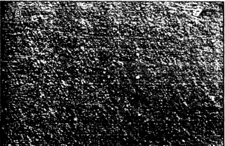
After ion nitriding, Tis0Niso specimens show a homo- geneous surface morphology with a color of golden yellow. The homogeniety and surface roughness are dependent on the nitriding parameters, as shown in Figs. l(a and b). Figs. 2(a-d) shows the X R D patterns of Tis0Niso specimens without and with ion nitriding at 700, 800 and 900 °C for 12 h, respectively. Before ion nitriding, as shown in Fig. 2(a), main B19' martensite and minor B2 parent phase are the major phases in the Tis0Nis0 matrix. However, after nitriding, as shown in Figs. 2 ( b - d ) , TiN and compounds are the main phases in the X R D patterns. The intensities of TiN and Ti2Ni compounds increase with increasing nitriding temper- ature as well as nitriding time. This indicates that the thickness of TiN and Ti2Ni compounds increases with increasing nitriding temperature and nitriding time. Because the hardnesses of TiN and Ti2Ni compounds are much higher than that of TisoNis0 matrix, the surface hardnesses of nitrided Tis0Niso specimens are quite high, as shown in Fig. 3. Meanwhile, the surface hardness, being related to the thickness of TiN and Ti2Ni com- pounds, increases with increasing nitriding temperature and nitriding time. The surface hardness can even reach 1400Hv for the experimental no. 9 specimen of Lg-nitrided Tis0Nis0 specimens.
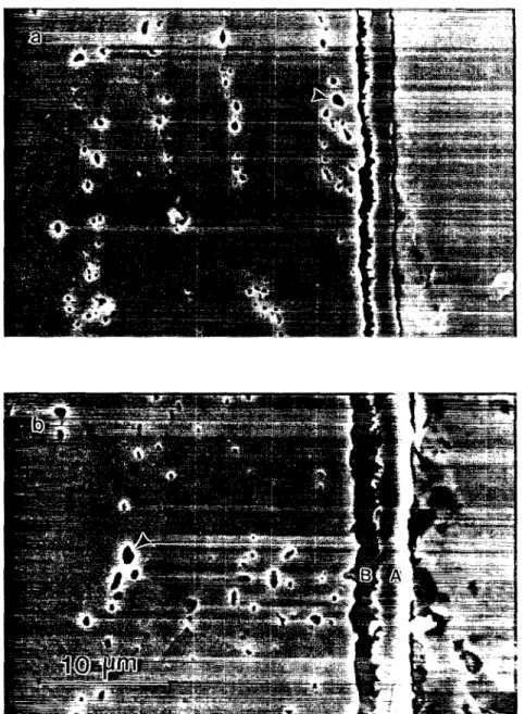
Typical cross-section micrographs of TisoNis0 speci- mens ion nitrided at 900 °C for 4 and 12 11 are shown in Figs. 4(a and b), respectively. On carefully examining Fig. 4, two different layers, an outer layer labeled A and an inner layer labeled B, are formed on the surface of nitrided Tis0Nis0 specimens. In addition, some fine Ti4Ni20 [27,28] particles introduced during the melting process are observed, as indicated by the arrows in the matrix.
These nitrided layers are the compound layers as is often seen in nitrided pure titanium and its alloys [10- 22]. As observed from the X R D patterns in Fig. 2, these nitrided layers should be TiN and Ti2Ni compound layers. The concentration profiles o f Ti, Ni and N in these nitrided layers of Tis0Nis0 specimens were exam- ined by EPMA. In order to obtain a precise composition analysis, the surface of the mounted specimens was carefully polished without any etching. Fig. 5 shows the EPMA line scan of Tis0Nis0 specimen nitrided at
S.K. Wu et aI. / Smface and Coatings Technology 92 (1997) 197-205 199
Fig. 1. Scanning electron rmcrographs of surface morphology of equiatomic TiNi alioy after ion nitriding at 900 °C for (a) 4 h and (b) 12 h.
900 °C x 12 h, 8 tort and [N2]/[H2] = 10. The intensity of the N k~ line increases from the surface to a maximum at the position of the outer compound layer (layer A). It then decreases continuously through the B layer and levels off in the interface of the B layer and TiNi matrix. It is difficult to confirm the existance of nitrogen diffu- sion layer in the substrate from Fig. 5 because of the rare concentration of nitrogen in the TiNi matrix. The intensity of the Ti k~ line also increases from the surface to a maximum at the A layer, and then gradually decreases through the B layer and levels off at the interface of the B layer and the TiNi matrix. The intensity of the Ni k~ line in A layer is rather weak. It continuously increases in the B layer and then levels off at the interface of the B layer and the TiNi matrix. From the results of X R D in Fig. 2 and the variations of Ti, Ni and N concentrations in Fig. 5, we propose
that a TiN compound forms in the A lawyer and a
Ti2Ni compound forms in the B layer. From Fig. 5, one can find that the TizNi layer can solid-solute quite a few nitrogen atoms, but the TiNi layer behaves oppositely.
3.2. Microstructures and composition analysis of ion- nitrided TisoNi4oCulo alloy
The TisoNi4oCulo ternary alloys have also been ion nitrided at the same nitriding process as that for equia- tomic TiNi alloys in order to compare their ion-nitriding behaviors with binary TisoNiso alloys. Figs. 6(a-d) shows the X R D patterns of TisoNi4oCu2o specimens without and with ion nitriding at 700, 800 and 900 °C for 12 h, respectively. Before ion nitriding, as shown in Fig. 6(a), B19+B19' martensite and B2 parent phase are the major phases in the TisoNi4oCulo matrix. This explains the fact that TisoNi40Cu~0 alloys exhibit
200 S.K. Wu er aL / Surface and Coatings Technology 92 (1997) 197-205 ,,--... v 0 3 2; z 4 v z z 2 O t B2 * B1£' 4 0 6 0 8 0 2 THETA (degree) b • T ~ t B2 t Z O 4 0 6 0 8 0 2 THETA
(degree)
!
z zi
0 3 z z o TiN • ThNi t B:I * * ; k J. 2 0 4 0 6 0 2 THETA (degree) o L L I , L ~ , 2 O oTN" t B2 8 0 4 0 6 0 8 0 2 THETA (degree)Fig. 2. XRD patterns of equiatomic TiNi specimens (a) without ion nitriding, and ion nitrided at (b) 700 °, (c) 800 ~C and (d) 900 °C for 12 h.
1500 > -c- v O3 m IO00- E t,,,- I 500. U G + + + t I I I I I I I I I I 0 1 2 3 4 5 6 7 8 9 L 9 [ o n n i t r i d i n g No. Fig. 3. The surface hardness of equiatomic TiNi alloy ion nitrided at various conditions of Table I.
B2~B19~B19' martensitic transformation, and mar- tensitic transformation temperatures of B2~B19 and Bt9~B19' occur at around room temperature [29]. However, after nitriding, as shown in Figs. 6(b-d), the peaks of TiN, TiaNi and Ti4o(Ni,Cu)6o compounds appear in the XRD patterns• Here, the chemical com- position of Ti4o(Ni,Cu)6o compound is quantified by EPMA and is regarded as a new phase. The peak intensities of these compounds increase with increasing nitriding temperature as well as nitriding time. This indicates that the thickness of these compounds increases
with increasing nitriding temperature and nitriding time. This feature can also be observed in Figs. 7 (a and b), which shows the cross-section micrographs of TisoNi4oCulo specimens ion nitrided at 900 °C for 4 and 12 h, respectively. In Fig. 7, three different layers, labeled A, B and C, are formed on the surface of nitrided TisoNi4oCu~o specimens. The concentration profiles of Ti, Ni, Cu and N in these nitrided layers of TisoNi4oCuto specimens have been examined by EPMA, and a typical line scan is shown in Fig. 8. The intensity of the N ks line increases from the surface to a maximum at the A layer, then decreases continuously through the B layer, and levels off at the interface of the B and C layers. The intensity of the Ti ks line also increases from the surface to a maximum at the A layer and then gradually drops through the B layer, reaching a mini- mum at the interface of the B and C layers. The intensity then increases a little and levels off at the interface of the C layer and TisoNi4oCuto matrix. The intensity of the Ni k~ line in the A layer is rather weak. It increases continuously at the interface of the A and B layers, through the B and C layers, and then levels off at the interface of the C layer and the TisoNi4oCulo matrix. The intensity of the Cu k, line in the A and B layers is also rather weak. It increases rapidly to a maximum at the C layer, then decreases continuously and levels off at the interface of the C layer and the TisoNi4oCulo matrix. From the results of XRD in Fig. 6 and the variations of Ti, Ni, Cu and N concentrations in Fig. 8, we propose that TiN, Ti2Ni and Ti40(Ni,Cu)6o com- pounds form in the A, B and C layers, respectively. It should be noted that the Ti2Ni layer can solve more Cu atoms than the TiN layer.
S.~ Wu et al. / Surface and Coatings Technology 92 (1997) 197-205 201
Fig. 4. Scanning electron micrographs of cross-sections of equiatomic TiNi alloy after ion nitriding at 900 °C for (a) 4 h and (b) 12 h.
3.3. Ion-nitriding mechanism in equiatomic T i N i shape m e m o r y alloy
The detailed reaction mechanism in the ion-nitriding process has not been clarified yet; however, two mecha- nisms has been proposed to explain the ion-nitriding process in steels [30,31]. The first mechanism proposes sputtering of Fe atoms, gasous reaction and then deposition on the specimen. The second mechanism proposes a surface reaction and then diffusion of nitro- gen into the specimen. To explain the ion-nitriding reaction in equiatomic TiNi alloy, we propose the four- step mechanism shown in Fig. 9. When the N + ions hit the surface of a workpiece, metal atoms (Ti and Ni) are detached and the workpiece is heated. At the same time, nonmetallic atoms such as carbon and oxygen are also
detached. In this way, the surface is freed from oxides, carbides etc., allowing N ÷ ions to be sputtered onto the clean surface [Fig. 9(I)]. Ti and Ni atoms which are detached from the surface can react with the highly reactive nitrogen atoms, which are sputtered in the plasma region or implanted on the surface of workpiece. Because the chemical affinity of Ti and N is much stronger than that of Ni and N [32], the combination of a N ÷ ion and a Ti atom occurs more easily than that of a N + ion and a Ni atom. This means that the material formed on the workpiece surface is composed of a much greater amount of T i N than NixN, as shown in layer A of Fig. 9 ( I I ) . We believe that the NixN phase was not found in the X R D results of Fig. 2 because the amount of NixN is too small to be detected. As the
202 XK. Wu et al / Surface and Coatings Technology 92 (1997) 197-205
Fig. 5. E P M A line scan profiles o f equiatomic TiNi alloy ion nitrided at 900 °C x 12 h, 8 torr and [N2]/IHz] = 10.
v z z r.q z z o BI9'* B [ 9 B2 20 4 0 6 0 80 2 T H E T A (degree) 2O o T ' u ~ • n e w p h a s e * T i l N i t * i ~ ~ 1 , ~ , , L J . , , ~ t ~ ~,,,,L~, 4 0 6 0 2 THETA (degree) 80 Crl 2: z "--2. 03 Z z o . o 2O • T i N TI, NI • n e w phase t B~ 20 4 0 4 0 6 0 80 2 T H E T A (degree) * T i . h'i I o * n g w phase ~" B2 * • o t 60 gO 2 THETA (degree)
Fig. 6. X R D patterns o f TisoNi4oCulo specimens (a) without ion nitriding, and ion nitrided at (b) 700 °C, (c) 800 °C and (d) 900 °C for 12 h.
Fig. 9(III) diffuse inwards. The Ti atoms can react more easily with N ÷ because the chemical affinity of Ti and N is stronger than that of Ni and N [32]. Thus, there is an outward driving force for Ti atoms which, together with the inward movement of N ÷ ions, forms TiN and thickens layer A. Meanwhile, the outward Ti atoms left behind layer A will react with TiNi to form Ti2Ni compound layer B [Fig. 9(IV)]. When the ion-nitriding temperature increases, the diffusion rates of Ti atoms
and N + ions also increase, and hence the TiN and TizNi layers grow more rapidly and the X R D intensities of these phases become stronger, as shown in Figs. 2 and 4. When the TiN in layer A (Fig. 9) reaches a certain thickness, it can become a barrier [33,34] and subsequently reduce the diffusion of N + ions into the TiaNi compound layer. This feature also reflects the fact that the undetectable nitrogen concentration at the rear part of the B layer and the TiNi matrix.
S.K. IVu et aI. / Surface and Coatings Technology 92 (1997) 197-205 203
Fig. 7. Scanning electron micrographs of cross-sections of TisoNi4oCulo ternary alloys after ion nitriding at 900 °C for (a) 4 h and (b) i2 h.
3.4. Effects of ion nitriding on the transformation temperatures and shape recovery ability o f the equiatomic TiNi alloy
Figs. 10 (a-c) shows the DSC curves of TisoNis0 speci- mens without and with ion nitriding at 800 °C for 4 and 12h, respectively. Fig. 10(a) represents a typical DSC curve of a stress-free TisoNiso alloy in which the exothennic and endothermic peaks are associated with the martensitic transformation of B2+--~B19'. The DSC curves for the ion-nitrided specimens, as shown in Figs. 10(b and c), exhibit similar martensitic trans- formation behaviors. However, the martensitic trans- formation temperatures are depressed to lower ones. qrlais phenomenon may be ascribed to two factors. First,
the constrained stress originating from the ion-nitrided layers will depress the martensitic transformation. Second, the penetration of N atoms or other impurities into the TiNi matrix as the interstitial atoms during the ion-nitriding process also have the possibility to depress the transformation temperatures [35].
Table 2 presents the measured shape recovery, RsME, at heating temperatures of Tf= 100 and 300 °C for the ion-nitrided equiatomic TiNi alloy. From Table 2, the shape recovery is found to be slightly reduced due to the ion nitriding. This result is reasonable because the nitrided compound layers do not exhibit the shape memory effect and their constrained effect on the TiNi matrix will also depress the shape recovery of TiNi matrix.
204 S.Ri Wu et al. / Surface and Coatings Technology 92 (t997) 197-205
Fig. 8. EPMA line scan profiles of TisoNi4oCuio ternary alloy ion nitrided at 900 °C x 12 h, 8 torr and [N2]/[Hz]= 10. N +
N +
N + N +(l)
SPUTTERING &
\
T ] \ . \ NiX NiIMPLANTATION
~
"~,T i ,,,,,~ T i ~,//,,'
TiNi
(II)
TiN FORMATION
TiN TiNi
TiNi
(III) D I F F U S I O N TiN=Z::Z!ZZ:ZZ~
N NN4i TiNi¢i TiNi4i
(IV) REACTION & ~
~
~
T
i
N
GROWTH
7_~.~ N / _ ~ _ _ Z ' ~ 2
Ni
TiNi
TiNi
Fig. 9. Schematic diagram of the ion nitriding mechanism of equia- tomic TiNi alloy.
4. Conclusions
The ion nitriding o f TisoNis0 and TisoNi4oCuto shape memory alloys has been investigated. The results obtained by means of microvickers hardness test, XRD, SEM and E P M A measurements can be summarized as follows:
(1) The ion nitrided equiatomic TiNi alloy consists
17s°c
AH=2aeJ2g
L
AH=24.6 J/g 995°(-:.]
o n /
57.1°c \
/ ' 1
/
21.8"C/
\49.6 C
--
I
~,
/ I.--~ "~ , '"~- -
~ J / g
A H=
2 3 . 5 Jig
'
O- A H =19.4Jtg
1
AH =22"5 J/9
41. *
. °
o
2 ? ) 4 ? )
do
8'o ' 1co
T e m p e r a t u r e (°C)
Fig. 10. The DSC curves of equiatomic TiNi specimens (a) without ion nitriding, and ion nitrided at 800 °C for (b) 4 h and (e) 12 h. of the TiN and Ti2Ni phases in the compound layer. The surface hardness, ascribed to the thickness o f TiN and Ti2Ni compound layer, increases with increasing nitriding temperature and time. For the ion nitrided TisoNi4oCulo ternary alloy, the Ti40(Ni,Cu)60 com-
S.I~ IVu et al. / Surface and Coatings Technology 92 (1997) 197-205 205 Table 2
The measured shape recovery, Rs,uE, at heating temperatures of Tf= 300 °C for the ion-nitrided equiatomic TiNi alloys
Experimental Shape recovery Rs~,,z (%)
no. of L9 Tf= 100 °C Tf> 300 °C None a 100.0 100.1 I 87.9 94.4 2 78.2 85.5 3 75.3 81.5 4 76.6 83.2 5 76.1 81.0 6 74.8 80.5 7 75.8 81.2 8 74.4 79.2 9 73.5 78.6
~Before ion nitriding,
p o u n d , as well as T i N a n d Ti2Ni p h a s e s , a p p e a r in the i o n - n i t r i d e d layers.
( 2 ) T h e i o n - n i t r i d i n g m e c h a n i s m o f e q u i a t o m i c T i N i a l l o y is s u g g e s t e d to i n c l u d e several s i m u l t a n e o u s steps: the s p u t t e r i n g o f t i t a n i u m a n d n i c k e l f r o m the surface, the f o r m a t i o n o f T i N , the diffusion o f N ÷ i o n s i n t o the m a t r i x , the r e a c t i o n o f Ti a n d N ÷ to f o r m T i N , a n d the r e a c t i o n o f T i a n d T i N i to f o r m Ti2Ni.
(3) T h e m a r t e n s i t i c t r a n s f o r m a t i o n t e m p e r a t u r e s a r e d e p r e s s e d slightly d u e to the c o n s t r a i n e d stress o r i g i n a t - ing f r o m the i o n - n i t r i d e d layers. A t the s a m e time, the i o n - n i t r i d e d layers e x h i b i t i n g n o s h a p e m e m o r y effect a n d b e h a v i n g the c o n s t r a i n e d effect o n the s u b s t r a t e will b o t h d e p r e s s slightly the s h a p e r e c o v e r y a b i l i t y o f T i N i alloys.
Acknowledgement
T h e a u t h o r s are p l e a s e d to a c k n o w l e d g e the financial s u p p o r t o f this r e s e a r c h b y the N a t i o n a l Science C o u n c i l ( N S C ) , R e p u b l i c o f C h i n a u n d e r G r a n t N o . N S C 84-2216-E002-027.
References
[1] S. Miyazaki, K. Otsuka, Y. Suzuki, Scripta MetalI. 15 (1981) 287-292.
[2] S. Miyazaki, Y. Ohmi, K. Otsuka, Y. Suzuki, ICOMAT-82, J. Phys. 43 (I982) 255-260.
[3] S. Miyazaki, T. Imai, Y. Igo, K. Otsuka, Metall. Trans. A 17A (1986) 115-I20.
[4] J.L. Jin, H.L. Wang, Acta MetalI. Sinica 24 (1988) A66-69. [5] D.Y. Li, Scripta MetaI1.34 (1996) 195-200.
[6] P. Clayton, Wear 162-164 (1993) 202-210.
[7] H.M. Liao, H.C. Lin, J.L. He, K.C. Chen, K.M. Lin, Proceedings of the International Conference on Displacive Transformations,
1996, in press.
[8] ASM Handbook, vol. 4, 9th ed, American Society for Metals, Metals Park, OH, 1991, p. 387.
[9] W. Kovacs, W. Russell, Proceedings of the ASM International Conference on Ion Nitriding, American Society for Metals, Metals : Park, OH, 1986, p. 9.
[i0] L.H. Chang, L.K. Lee, H.C. Peng, C.Y. Wang, Acta MetalI. Sin. 20 (1984) A221-A228.in Chinese
[ 11] A. Raveh, P.L. Hansen, R. Avni, A. Grill, Surf. Coatings Technol, 38 (1989) 339-351.
[12] E. Metin, O.T. Inal, Metall. Trans. A 20 (I989) 1819-1823. [13] E. Metin, O.T. Inal, Mater. Sci. Engng A145 (1991) 65-77. [i4] E. Metin, Scr. Metall. 26 (1992) 1193-1197.
[15] H.J. Brading, P.H. Morton, T. Bell, L.G. Earwaker, Surf. Engng 8 (1992) 206-212.
[i6] A. Ravech, R. Avni, A. Grill, Thin Solid Films 186 (1990) 241-256.
[17] FIMI Kustas, M.S. Misra, R. Wei, P.J. Wilbur, J.A. Knapp, Surf. Coat. Technol. 51 (1992) 100-105.
[18] P. Scradi, B. Tesi, T. Bacci, C. Gianoglio, Surf. Coatings Technol. 41 (1990) 83-91.
[19] K.T. Rie, T. Lampe, Mater. Sci. Engng 69 (1985) 473-48I. [20] E. Rolinski, Mater. Sci. Engng 100 (i988) 193-199. [21] R. Avni, T. Spalvins, Mater. Sci. Engng 95 (1987) 237-246. [22] C.L. Chu, S.K. Wu, Surf. Coatings Technol. 78 (1996) 211-226. [23] P. Moine, O. Popoola, Scripta Mat. 20 (I986) 305-310. [24] K. Endo, R. Sachdeva, Y. Araki, H. Phno, Proceedings of the
International Conference on Shape Memory and Superelastic Technologies, SMST-94, I994, pp. 233-237.
[25] P.J. Ross, Taguchi Techniques for Quality Engineering, McGraw- Hill, New York, 1988, p. 23.
[26] H.C. Lin, S.K. Wu, Scr. Metall. Mater. 26 (1992) 59-62. [27] P. Duwez, J.L. Taylor, AIME Trans. 188 (i950) 1173.
[28] G.M. Michal, Diffusionless Transformation in TiNi, Ph.D thesis, Stanford University, CA, I979.
[29] Y.C. Lo, S.K. Wu, H.E. Horng, Acta Metall. Mater. 41 (I993) 747-759.
[30] B. Edenhofer, Heat Treat. Metals I (1974) 23-26.
[31] T. Spalvins, Proceedings of the ASM International Conference on Ion Nitriding, American Society for Metals, Metals Park, OH, 1986, p. I.
[32] C.E. Wicks, F.E. Block, Thermodynamic Properties of 65 Ele- ments - Their Oxides, Halides, Carbides, and Nitrides, US Gov- ernment Printing Office, Washington, DC, 1963, pp, 13-124. [33] M. Wittmer, Appl. Phys. Lett. 36 (6) (1980) 456-458. [34] M. Wittmer, Appl. Phys. Lett. 37 (6) (1980) 540-542.
[35] T. Honma, Shape Memory Alloys, Gordon and Breach, Amster- dam, i987, pp. 89-101.

![Fig. 5. E P M A line scan profiles o f equiatomic TiNi alloy ion nitrided at 900 °C x 12 h, 8 torr and [N2]/IHz] = 10](https://thumb-ap.123doks.com/thumbv2/9libinfo/8662691.195149/6.972.263.708.98.443/fig-profiles-equiatomic-tini-alloy-nitrided-torr-ihz.webp)

![Fig. 8. EPMA line scan profiles of TisoNi4oCuio ternary alloy ion nitrided at 900 °C x 12 h, 8 torr and [N2]/[Hz]= 10](https://thumb-ap.123doks.com/thumbv2/9libinfo/8662691.195149/8.972.264.709.97.445/fig-epma-profiles-tisoni-ocuio-ternary-alloy-nitrided.webp)
