Suppression of spatial hole burning in a
solid-state laser with the degenerate resonator
configuration
Po-Tse Tai and Wen-Feng Hsieh
Department of Photonics and Institute of Electro-Optical Engineering National Chiao Tung University 1001 Tahsueh Rd., Hsinchu, Taiwan 3005
[email protected] Hsiao-Hua Wu
Department of physics, Tunghai University 181 Sec. 3 Chung Kang Rd. Taichung 407, Taiwan
Abstract: Under degenerate resonator configuration and tightly focused pump beam in a linear-cavity solid-state laser, the spatial hole-burning effect can be suppressed. This laser can attain very high intensity in the gain medium due to shrinkage of its beam waist to match the pump beam and therefore most of its gain is depleted even by a standing wave. This was demonstrated by a simulation with spatial dependent rate equations and
experiment results of a plano-concave Nd:YVO4 laser. The suppression
effect was observed up to 20 times the pump threshold.
2005 Optical Society of America
OCIS codes: (140.3410) Laser resonators; (140.3580) Lasers, solid-state References and links
1. V. Evtuhov and A. E. Siegman, “A “twisted-mode” technique for obtaining axially uniform energy density in a laser cavity,” Appl. Opt. 4, 142-143 (1965).
2. K. Otsuka and K. Kubodera, “Effects of Auger recombination process on laser dynamics,” IEEE J. Quantum Electron. QE-16, 538-541 (1980).
3. K. Otsuka, P. Mandel and E. A. Viktorov, “Breakup of cw multimode oscillations and low-frequency instability in a microchip solid-state laser by high density pumping,” Phy. Rev. A, 56, 3226-3232 (1997). 4. L. Meilhac, G. Pauliat and G. Roosen, “Determination of the energy diffusion and of the Auger
upconversion constants in a Nd:YVO4 standing-wave laser,” Opt. Commun. 203, 341-347 (2002).
5. C. H. Chen, P. T. Tai, M. D. Wei, and W. F. Hsieh, “Multibeam-waist modes in an end-pumped Nd:YVO4
laser,” J. Opt. Soc. Am. B 20, 1220-1226 (2003).
6. H. H. Wu and W. F. Hsieh, “Observations of multipass transverse modes in an axially pumped solid-state laser with different fractionally degenerate resonator configurations,” J. Opt. Soc. Am. B 18, 7-12 (2001). 7. G. J. Kintz and T. Baer, “single-frequency operation in solid-state laser materials with short absorption
depths,” IEEE J. Quantum Electron. 26, 1457-1459 (1990).
8. Y. F. Chen, C. C. Liao and S. C. Wang, “Determination of the Auger upconversion rate in fiber-coupled diode end-pumped Nd:YAG and Nd:YVO4 crystals,” Appl. Phys. B 70, 487-490 (2000).
9. J. R. O’Connor, “Unusual crystal-field energy levels and efficient laser properties of YVO4:Nd,” Appl.
Phys. Lett. 9, 407-409 (1966).
10. O. Guillot-Noel, V. Mehta, B. Viana, D. Gourier, M. Boukhris, and S. Jandl, “Evidence of ferromagnetically coupled Nd3+ ion pairs in weakly doped Nd:LiYF
4 and Nd:YVO4 crystals as revealed by
high-resolution optical and EPR spectroscopies,” Phys. Rev. B, 61, 15338 (2000).
11. D. K. Sardar and R. M. Yow, “Stark components of 4F3/2, 4I9/2 and 4I11/2 mainfold energy levels and effects of temperature on the laser transition of Nd3+ in YVO4,” Opt. Matter. 14, 5-11 (2000).
12. F. J. Manjon, S. Jandl, G. Riou, B. Ferrand, and K. Syassen, “Effect of pressure on crystal-field transitions of Nd-doped YVO4,” Phys. Rev. B, 69, 165121 (2004).
13. P. T. Tai, C. H. Chen, and W. F. Hsieh, “Direct generation of optical bottle beams from a tightly focused end-pumped solid-state laser,” Opt. Express 12, 5827-5833 (2004),
http://www.opticsexpress.org/abstract.cfm?URI=OPEX-12-24-5827
14. C. H. Chen, P. T. Tai, and W. F. Hsieh, “bottle beam from a bare laser for single-beam trapping,” Appl. Opt. 43, 6001-6006 (2004)
1. Introduction
The single-frequency laser is essential for stable operation of intracavity frequency doubling, precision measurement, high-resolution spectroscopy, and laser trapping or cooling. The most common method of obtaining the single-frequency operation in a homogeneously broadened solid-state laser is to build a traveling wave cavity, usually by means of a ring cavity together with an intracavity optical diode, so as to prevent the spatial hole-burning effect. To acquire single-frequency operation in a linear cavity, other ways are required to diminish the spatial hole-burning effect. For example, a twisted mode technique [1] had been proposed to achieve axially uniform energy density in the laser cavity. In addition, the mechanisms of Auger upconversion and energy diffusion in the laser crystal were also employed to reduce the spatial hole-burning effect [2-4].
Recently, it was shown that a plano-concave cavity with the degenerate resonator configuration could support more or less arbitrary beam distribution. Under tightly focused pump beam, the laser exhibited the shrinkage of beam waist and the lower pump threshold than the neighboring configurations [5, 6]. In this Article, we report a novel way by employing the degenerate resonator configuration to relief the spatial hole-burning effect. Because the laser with a degenerate resonator configuration is capable of self-adjusting the mode distribution to match the small pump beam, very high intensity is able to attain in the gain medium of this laser. Most of the gain, therefore, can be depleted even by a standing wave. The spatial hole-burning effect is then effectively suppressed. This was numerically simulated in terms of a spatial dependent rate equation and experimentally demonstrated by
using a Nd:YVO4 laser. The Nd:YVO4 laser crystal has high absorption coefficient which is a
merit for single-frequency operation in a standing-wave cavity, but the pump power is usually limited to slightly above the threshold [7]. Our method, however, is capable of suppressing the spatial hole-burning effect up to 20 times the pump threshold.
2. Theoretical model and simulation
In order to investigate the spatial hole-burning effect in a plano-concave Nd:YVO4 laser, we
employ a spatial dependent rate equation. By taking into account both the Auger upconversion and energy diffusion effects, the rate equation for the density of population inversion N(z) in an ideal four-level system can be expressed as [2, 4, 8]
( )
( )
( ) ( )
( )
A N( )
z z z N D z N I z I z R z N t s 2 2 2 1 τ τ τ τ − ∂ ∂ + + − = ∂ ∂ , (1)where z is the cavity axis with z = 0 at the flat mirror, R(z) is the pump rate, Is is the saturation
intensity, τ is the spontaneous emission lifetime, D is the diffusion constant, and A is the
Auger upconversion coefficient. Assuming a low roundtrip loss in the plane wave approximation, we can write the intensity I(z) of standing wave as
I
( )
z I 2( )
kz , (2)0sin
4
=
where k is the propagation number and I0 is the average intracavity intensity. Because we do
not consider the radial effect in Eq. (1), the pump rate can be written as
( )
2 z p pP
e
R z
h
w
αν π
α
−=
×
×
, (3)where Pp is the incident pump power, h is the Planck’s constant, ν is the pump frequency, wp
is the pump size, and α is the absorption coefficient at pump wavelength. Under the
steady-state condition, we substituted Eqs. (2) and (3) into (1), and numerically solved the equation by the Newton’s method to obtain the spatial profile of N(z). The Auger upconversion
coefficient A = 3x10-21 m3/s [4, 8], diffusion constant D = 0.7x10⁻¹¹ m2/s [4], absorption
coefficient α = 31.4 cm-1 , and saturation intensity I
s = 1.19x10⁷ J/(m2s) are used in our
simulation.
Usually the laser is expected to operate at the single longitudinal mode when the pump power is just above the threshold. From the Ref. 7, we estimate that the second longitudinal
mode would begin to oscillate at γ = 1.78 where γ is the ratio of pump power to laser threshold,
therefore, we will discuss the numerical results using the pump power around γ = 1.78.
Because the thickness of the laser crystal is less than the Rayleigh parameter of the pump
beam, we assume that the pump size wp is constant throughout the crystal. When a laser
operates in the vicinity of g1g2 = 1/4 with a curve mirror of 8-cm curvature, the radius of the
fundamental transverse mode is about 108µm. It corresponds to Rayleigh parameter of about
34 mm which is much longer than the length of gain medium of 1 mm. In addition, the plane wave assumption is adequate for a beam with or close to Gaussian profile. Note that the laser
beam spot in vicinity of flat mirror (gain medium) is almost equal to the pumping size of wp =
20 µm and similar to Gaussian profile [5] when it is operated with the degenerate resonator
configuration under tightly-focused pumping. The plane wave assumption in Eq. (2) is still
valid even with the high-order Laguerre-Gaussian mode up to LG12,0, whereas, the shrinkage
of beam spot can be observed at the degeneracy with only a superposition of LG00 and the
lowest degenerate mode, e.g., LG3,0 for g1g2=1/4 [13].
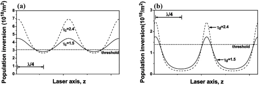
Figure 1(a) is the spatial profile of N(z) for a laser operated at cavity length L = 6.06-cm which is a typical example of population inversion in a standing wave resonator. It only burns a small hole of N(z) at anti-node of standing wave and leaves a lot of gain for the second longitudinal mode. The horizontal dash line in this figure stands for the threshold population inversion which is equal to the pump power of 33 mW, the solid and dash curves respectively
show N(z) for the laser operating at γc = 1.5 and γc = 2.4 where the subscript c denotes the
conventional cavity. To allow the second mode to oscillate (γc > 1.78), the residual population
inversion should higher than that for the laser operating at γc = 1.5 as shown in Fig. 1(a).
0 1 2 3 4 5 6 7 8 λ/4 threshold Laser axis, z P opul ati on i n ver sion (10 18/m 2) γc=1.5 γc=2.4 0 1 2 3 Population inver sion(10 18/m 2) Laser axis, z γd=1.5 γd=2.4 threshold λ/4 0 1 2 3 4 5 6 7 8 λ/4 threshold Laser axis, z P opul ati on i n ver sion (10 18/m 2) γc=1.5 γc=2.4 0 1 2 3 Population inver sion(10 18/m 2) Laser axis, z γd=1.5 γd=2.4 threshold λ/4 (a) (b)
Fig. 1 Numerical spatial distribution of steady-state upper level density to show influence of spatial hole-burning effect. The normalized pumping γ (to the threshold) for both of the conventional laser operated at L=6.06cm (a) and bottle beam laser at g1g2=1/4 (b).
If we operate the laser at the degenerate resonator configuration where g1g2 = 1/4 (L = 6.0
cm), good overlapping between the pumping and the laser beam will result in a lower laser
threshold which equals to 15mW. The beam radius will be about 20 µm which approximates
to the size of pump. The intracavity intensity at the beam waist (z = 0) is about 29 times higher than that of the laser with the conventional cavity (L = 6.06-cm). Because of the very high intracavity intensity, there leaves only a little residual population inversion above the threshold which is located around the node of the standing wave, as shown in Fig. 1(b). The horizontal dash line again stands for the threshold population inversion. In addition, other
longitudinal modes could have significant access to the residual inversion only if they had at
least π/2 phase shift relative to the first mode [7]. Two lasing frequencies, which is in-phase
at beginning, will possess π/2 phase difference after propagating a dephasing length. Usually
the first lasing mode in a homogeneously broadened gain medium is located near the center of gain profile, and the shortest dephasing length is provided by the maximum frequency difference. So we used half of bandwidth to estimate the shortest dephasing length to be
700µm. This implies that the other longitudinal mode needs more than 2.3 times absorption
depth of Nd:YVO4, which is reciprocal of absorption coefficient α, to extract enough residual
gain to oscillate. From Fig. 1(b), we see that the residual population inversion for γd = 1.5,
where the subscript d denotes the degenerate cavity, is too small to allow the oscillation of the
second mode. Nevertheless, for γd = 2.4 or even higher pump power, because higher residual
population inversion occurs at node of the standing wave the second mode still can not obtain the sufficient gain. In addition, it is worth to mention that by neglecting the energy diffusion and Auger upconversion effects, the last two terms of the right-hand side of Eq. (1), we still obtained the similar numerical results of Fig. 1(b). This means that the effects of Auger upconversion and the energy diffusion are negligible and can be ruled out in our case. Therefore, we conclude that the laser with the degenerate resonator configuration is capable of suppressing the spatial hole-burning effect by means of gain saturation through the very high intensity in the gain medium.
3. Experimental setup and results
The experiment is performed in a Nd:YVO4 laser with a plano-concave cavity. The detail
setup is similar to that described in Ref. 5. A 1-mm thick 1% Nd:YVO4 crystal is used as the
gain medium. The crystal facet faced toward the pumping beam has a dichroic coating of high transmission 808 nm pump wavelength as well as high reflection at 1064 nm laser wavelength and is served as the flat mirror. The other facet is antireflection coated at 1064
nm to avoid the effect of intracavity etalons. A curve mirror with radius of curvature Rc = 8
cm and 10% transmission at 1064 nm is employed as the output coupler. It is mounted on a translational stage so that we can adjust the cavity length L and equivalently change the resonator configuration. The pump source is a cw Ti-sapphire laser operated with a nearly
TEM00 mode. We place a lens with different focal lengths in front of the crystal to adjust the
pumping spot size. A photodetector (rise time < 0.3 ns) together with a RF spectrum analyzer (HP8560E, bandwidth 2.9 GHz) was used for measuring the mode beating and the relaxation oscillation. The optical spectrum was measured by using a Fabry-Perot interferometer (FPI, Burleigh) having finesse > 150 corresponding to a spectral resolution of 100 MHz for a 15 GHz free spectral range (FSR). In addition, the pump size determined by the standard
knife-edge method is 20 µm, which is less than one-fifth of the waist radius (108 µm) of the cold
cavity mode. The cavity length corresponding to the degenerate resonator configuration is determined by minimum pump threshold [6]. In this experiment, we operated the laser around the 1/3-degeneracy (L = 6 cm) where corresponds to the longitudinal mode spacing of about 2.4 GHz.
Figure 2 shows a typical single-frequency optical spectrum measured by FPI when the
laser is operated at γ < 1.8 (~ 1.78) in the conventional cavity configuration (L = 6.06 cm).
The second longitudinal mode appears when the γc = 1.8 > 1.78 (threshold is 33 mW). The
experiment observation agrees well with the theoretical estimation according to the Ref. 7.
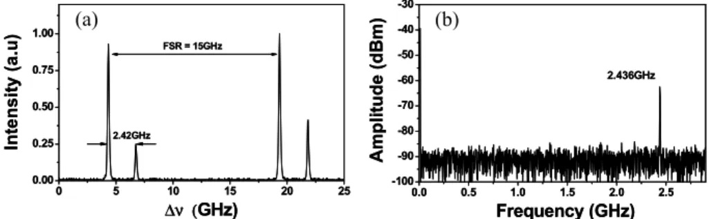
Figure 3 (a) and (b) respectively show the FPI and the RF spectra for γc = 2.7 (pumping power
Pp = 90 mW). We can clearly see the second longitudinal mode and the beating from these
two longitudinal modes. As the pump power increases to over 133 mW (γc = 4), we found that
an extra lasing mode appears at 1.1 GHz away from the main features of the FPI spectrum but no corresponding mode beating can be detected by the RF spectrum analyzer. Therefore, we suspected that the spectral spacing of these two lasing modes is larger than the bandwidth of the RF spectrum analyzer (2.9 GHz). Indeed, when the FPI with larger FSR (150 GHz or even 300 GHz) is used, the measured mode spacing becomes 40 GHz.
0 5 10 15 20 25 0.00 0.25 0.50 0.75 1.00 FSR = 15 GHz ∆ν (GHz) In te n si ty (a .u )
Fig. 2 Single frequency optical spectrum of the Fabry-Perot interferometer with FSR = 15 GHz when the pumping is set below 1.8 times threshold.
0 5 10 15 20 25 0.00 0.25 0.50 0.75 1.00 Int ensit y (a. u) ∆ν (GHz) 2.42GHz FSR = 15GHz 0.0 0.5 1.0 1.5 2.0 2.5 -100 -90 -80 -70 -60 -50 -40 -30 2.436GHz Frequency (GHz) A m pl it ud e ( d B m ) 0 5 10 15 20 25 0.00 0.25 0.50 0.75 1.00 Int ensit y (a. u) ∆ν (GHz) 2.42GHz FSR = 15GHz 0.0 0.5 1.0 1.5 2.0 2.5 -100 -90 -80 -70 -60 -50 -40 -30 2.436GHz Frequency (GHz) A m pl it ud e ( d B m ) (a) (b)
Fig. 3 Typical multiple optical frequency and corresponding RF spectrum for the common laser at L=6.06cm. (a) The Fabry-Perot interferometer shows two longitudinal lasing modes with spacing of about 2.42 GHz and (b) the beat frequency of two longitudinal modes measured by the RF analyzer.
On the other hand, as the cavity is adjusted to the degenerate resonator configuration (L = 6 cm), the single frequency operation is observed, as shown in Fig. 2, for the pump power as
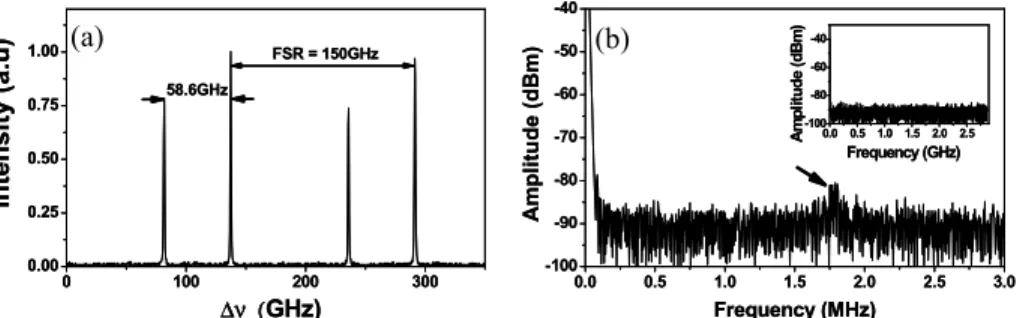
high as 30 mW. By raising the pump power to above 30 mW (γd = 2), we found that the
second mode appear in the FPI spectrum which is located 58.6 GHz away from the first mode rather than ~2.4 GHz. The next nearest neighboring longitudinal mode is not observed even the pumping power increases as high as we can. The FPI and the corresponding RF spectrum
at Pp = 310 mW or γd ~20 are shown in the Fig. 4(a) and (b) respectively. The inset of Fig.
4(b) shows that there is neither longitudinal nor transverse mode beating within the bandwidth of the RF spectrum analyzer, the arrow in this figure shows only one relaxation oscillation peak (2.4 MHz) existing in the RF spectrum. Someone may doubt whether the mode spacing of 58.6 GHz comes from the intracavity etalon effect. However, the etalon mode spacing is
72 GHz in this experiment; and there is an antireflection coating at 1064 nm on the Nd:YVO4
facet to avoid the effect of intracavity etalons.
As the simulated results discussed above, the laser with the degenerate resonator configuration is able to deplete most of the population inversion in a homogeneous broadened gain medium. We therefore expect that the second mode 58.6 GHz away from the first mode may have different origin of emission or arise from different manifold of transition (sub-peak of inhomogeneous gain profile). Similarly, the sub-peak of the gain profile will also result in the occurrence of the second mode in the conventional cavity at higher pump power, which is
40 GHz away from the first mode. In the Nd:YVO4 crystal, the crystal field interaction gives
rise to the Stark splitting at the satellite of 4F
3/2, 4I9/2, and 4I11/2 [9]. Under high-resolution
absorption and luminescence studies, it was found that the satellite energy of 4F
3/2 Æ 4I9/2
transition depended on the Nd3+ concentration [10]. The lasing transition around 1064 nm is
attributed to 4F
3/2 Æ 4I11/2. It contains two closely transitions R1 Æ Y1 and R2 Æ Y2 with
frequency difference of 90 GHz under 2% Nd3+ doping and 21 GHz under 0.56% Nd3+ doping
[11, 12]. The doping concentration used in our experiment is 1%, it is quite reasonable to obtain the frequency difference of ~42 GHz by simple interpolation. The frequency
difference which is estimated by interpolation is in good agreement with our observation in the conventional laser cavity. Note that because the second mode has a frequency more than 40 GHz away from the first mode, it would be easily filtered out, for example, by a grating with 1800 grooves. In principle, it is possible to design a cavity that delivers the same tight
beam size in a fundamental TEM00 mode and achieve the same effect. However, such a cavity
is usually operating close to the edge of stability and needs to accurately adjust the cavity length according to the spot size of the pump beam. Our scheme, in contrast, is operated within the stability region away from the edge of stability. Without knowing the pump beam size in advance, the laser with a degenerate resonator configuration can self-adjust the mode distribution to match the small pump beam and as a result the spatial hole-burning effect is suppressed. 0 100 200 300 0.00 0.25 0.50 0.75 1.00 ∆ν (GHz) 58.6GHz FSR = 150GHz Intensity (a.u) 0.0 0.5 1.0 1.5 2.0 2.5 3.0 -100 -90 -80 -70 -60 -50 -40 0.0 0.5 1.0 1.5 2.0 2.5 -100 -80 -60 -40 A m pl itud e ( dB m ) Frequency (GHz) Ampl it u d e (dBm) Frequency (MHz) 0 100 200 300 0.00 0.25 0.50 0.75 1.00 ∆ν (GHz) 58.6GHz FSR = 150GHz Intensity (a.u) 0.0 0.5 1.0 1.5 2.0 2.5 3.0 -100 -90 -80 -70 -60 -50 -40 0.0 0.5 1.0 1.5 2.0 2.5 -100 -80 -60 -40 A m pl itud e ( dB m ) Frequency (GHz) Ampl it u d e (dBm) Frequency (MHz) (a) (b)
Fig. 4 Multiple optical frequency and corresponding RF spectrum under 310mW pumping at g1g2=1/4.
(a) The FPI spectrum shows mode spacing of about 58.6GHz but without longitudinal beating of 2.42 GHz or transverse mode beating in the RF spectrum in (b). An arrow points out the peak due to relaxation oscillation.
4. Conclusion
We have theoretically shown and experimentally demonstrated that the spatial hole-burning effect can be suppressed by using a plano-concave cavity with degenerate resonator configuration under a tightly focusing pump beam. It not only has the merits of the lowest threshold and stable output but also is independent of the gain medium. The same resonator configuration has been employed to generate the multiple beam waists and the optical bottle beam [13, 14], it has potential applications for trapping atoms in the dark field if the proper gain medium is chosen to generate blue-detuned single frequency laser beam.
Acknowledgments
The research was partially supported by the National Science Council of the Republic of China under grant NSC93-2112-M-009-035 and NSC91-2112-M-029-004. Mr. P. T. Tai gratefully acknowledges the NSC for providing fellowship.