Syh-Shiuh Yeh
Pau-Lo Hsu
Department of Electrical and Control Engineering, National Ctiiao Tung University, Hsinchu, 300 Taiwan [email protected]
Theory and Applications of
tlie Robust Cross-Coupled
Control Design
The cross-coupled control (CCC) has been recognized as an efficient motion controller that reduces contouring errors, but theoretical analysis of it is lacking, and there is no systematic design approach for obtaining a CCC system with guaranteed control perfor-mance. Consequently, the compensators C in CCC are commonly implemented in a PID structure and their contouring accuracy is usually degraded in real applications under different operating conditions. In an attempt to overcome the CCC design limitations described above, this paper introduces a robust CCC design based on a novel formula-tion: the contouring error transfer function (CETFj, leading to an equivalent formulation as in the feedback control design problem. Then, methods in robust control design can be readily employed to achieve robust CCC with specified stability margins and guaranteed contouring performance. Furthermore, the proposed design has been verified as being internally stable. All provided experimental results indicate that the proposed robust CCC design consistently renders satisfactory contouring accuracy under different operating conditions.
I Introduction
In motion control, feedback controllers for multiple-axis sys-tems are usually designed independently such that each axial servomechanism can track input commands accurately to reduce tracking errors. However, such control structures can not further reduce tracking or contouring errors because of inherent servo lag, stick friction, or backlash constraints. Zero phase error tracking control (ZPETC) was proposed by Tomizuka (1987) to reduce effectively tracking errors. To reduce contouring errors, Koren (1980) proposed the cross-coupled controller (CCC) which sub-stantially improves the contouring accuracy of multiple-axis sys-tems by applying position error adjustment to each axis. Moreover, other CCCs of various types have been reported since Koren's original publication to achieve desirable contouring performance. For example, adaptive CCC was proposed by Chuang and Liu (1991, 1992), optimal CCC design method was proposed by Kulkami and Srinivasan (1989, 1990), and fuzzy logic controlled CCC was proposed by Koren and Jee (1995). In general, the structure of CCC includes (1) cross-coupling gains {C^, C,) and (2) a compensator C. Recently, a variable-gain CCC was proposed (Koren and Lo, 1991), in which the gains (C^, C,) are adjusted in real time according to the contour geometry to further improve contouring accuracy.
Variable-gain CCC control systems process different contouring commands as parameter-varying systems. Moreover, motion con-trol systems are usually operated under varied external loading. Therefore, the main objective that enable the compensator C design in a CCC to cope with different operating conditions in practice are
(1) effective reduction of contouring errors under differing contour conditions and loading, and
(2) guaranteeing that the CCC system will be stable under different operating conditions.
To meet these requirements, the compensator C must be de-signed with sufficient stability and guaranteed contouring
per-formance. However, available CCC controllers have not been systematically analyzed yet, and PID-type compensators C that do not guarantee stability and performance are commonly adopted.
This paper presents a robust CCC design method by introducing a novel formulation, the contouring error transfer function (CETF) that describes the dynamic relationship between contouring errors produced by coupled-control systems and those produced by uncoupled-control systems. By this formulation, the CCC design can be simply represented in a feedback control design problem. Thus, robustness theories and analysis of control design can be directly employed in CCC design to achieve desirable stability margins and performance. In this paper, we use the quantitative feedback theory (QFT) design algorithm (Horowitz and Sidi, 1972) to achieve robust CCC with specified 50 dB gain margin and 90 deg phase margin. Furthermore, analysis indicates that the present robust CCC design is internally stable. Under different commands and loading conditions, experimental results indicate that the present robust CCC design consistently renders satisfac-tory contouring accuracy.
II CCC System Contouring Errors
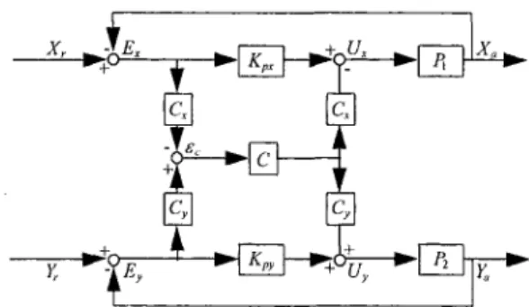
A two-axis cross-coupled motion-control system is repre-sented in Fig. 1. This CCC motion-control system has three degrees of freedom, two position loop controllers {Kj,^, K,,y) and a compensator C. Figure 1 can be further simplified, as shown in Fig. 2. In general, if the position loop proportional gains
(Kp:,, Kpy) are set too small, the system response becomes
sluggish, however large gains setting may cause system oscil-lation. Practically, the damping ratio of each position feedback loop is expected to be larger than 0.707 to avoid oscillatory motion.
Variable Gains in CCC. In the variable-gain CCC design, the
cross-coupling gains (C;^, C,) are directly determined according to the contouring commands (Koren and Lo, 1991). For linear con-tours, the gains (C,, C,) are determined by
Contributed by the Dynamic Systems and Control Division for publication in the JOURNAL OF DYNAMIC SYSTEMS, MEASUREMENT, AND CONTROL. Manuscript received by the Dynamic Systems and Control Division October 7, 1996. Associate Technical Editor: Tsu-Chin Tsao.
C^ = sin 6 C„ = cos
(1)
IVA "•
''•'°°"2.^>j--.jg.;;j^^>^3;^51^^ };(coiint)
Fig. 1 Two-axis cross-coupied motion-control system
where d is the inclination angle of a linear contour with respect to X-axis. For circular contours, the variable gains (C,, C,) are determined by sin 6 C, = cos e -I-2R EL 2R (3) (4)
Fig. 2 Block diagram of the coupled motion-control system
1 -1- P^K^y 1 + P,K^, 1
where R is the circular contour radius, (£,, E,) are X-axis and Y-axis error signals, respectively; Q is the circular contour traversal angle input command. As shown in Eqs. (l)-(4), the cross-coupling gains are determined by the orientation in linear motions and by the traversal angle in circular motions. Therefore, the CCC control system which combines the CCC controller and the plant is a parameter-varying system. If the axial errors are much smaller than the circular motion circle radius (Koren and Lo, 1991), the cross-coupling gains {C,, C,,) in Eqs. (l)-(4) can be reasonably confined in the range of [—1, 1] in the CCC design. The template used for the QFT design algorithm can be thus constructed for further robust design.
Uncoupled Systems. To analyze an uncoupled system, let C =
0 and e„ be the uncoupled motion-control system contouring error, where the subscript "o" represents the open cross-coupling con-nection. The corresponding variables shown in Fig. 2 are repre-sented as
(1 +P2K„){1 +P,K,J
X [ - ( l +P,KJCAI +P,KJCA (10)
Cross-Coupled Systems. Define e^ as the contouring error of a
coupled motion-control system, where the subscript "c" means "coupled system". As shown in Fig. 2, if C 7^ 0 the variables are represented as
6 o t^y^y i^X^X
UX ~~ l^px^xy ^y ^ ".py^y
X„ = P,U,; Y.^P^Uy
From Eqs. (6)-(8), the axial errors ( £ „ Ey) are
1 1 Ex = + P,K„ - X/, Ey — + P2Kpy Yr (5) (6) (7) (8) (9) F = F C — F C ^c ^y^y ^x^x
U, = Kp,E, - Ce,C,; Uy = K^yEy + Ce.Cy X, = P,Ux; Y„ = P,Uy
E, = X,-X,; Ey=Y,-Y,
From Eqs. (12)-(14), the axial errors {E^, Ey) are
Yr ~ CCyP^Bc ^_ X, + CC,P,e, 1 + P , r „ ' -^^ 1 + P,K„ (11) (12) (13) (14) (15) When Eq. (15) is substituted into Eq. (11), the contouring error of the coupled motion-control system e„ becomes
When Eq. (9) is substituted into Eq. (5), the contouring error of the uncoupled system becomes
1 + PiKpy 1 1 + P^Kpx (1 +P^Kpy){\ +P,KJ N o m e n c l a t u r e C = compensator in CCC C„, C,, = numerator and denumator of
the compensator C
C,, Cy = variable gains in CCC E,, Ey = position error of X and Y
axes
GM, PM = gain margin and phase mar-gin, respectively
Ka = D/A gain (2.442 X 10 ' V/pulse)
Ke = encoder gain (632.62 pules/ rad)
Kpx, K„ = proportional gain controllers
for X and Y position loops
Mi„ uip = the maximum gain M,, and
corresponding frequency to,, of contouring error transfer function T
Pi, Pz = equivalent controlled plant of
X and Y axes
T = contouring error transfer
func-tion
Be = contouring error of coupled
motion control system E„ = contouring error of uncoupled
motion control system iw„ = reference frequency of
- 9 r - ^
C
K
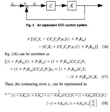
Fig. 3 An equivalent CCC controi system
X[{C,Y,- CC,C,P^e,){\ + P^K,:)
- (CX + CCC./'.eJCl + P^/fJ] (16)
Eq. (16) can be rewritten as
[(1 + P^K,,){\ + />,*:,,) + (1 + P,K^:)CC,C,P^ + (1 + P^K,,)CC,C,P,-\e, = (1 + P , . f : J C , F ,
- (1 + P,K^y)CJC, (17) Then, the contouring error e^ can be represented as
1
"' " [(1 + P,K„)(\ + P,K,,) + (1 + P,K,,)CC,C,P2 + (1 + f2/i:„)CC,C,P,] •
[-(1 + /'2A:„)C, (1 + / > , ^ , , ) c j [ ^ ; ] (18)
III The Contouring Error Transfer Function
Using Eqs. (10) and (18), and introducing the following two representations
a = (l + ^ , , P i ) ( l +K,yP2)
p = (1 + K,,Pi)CC,C,P2 + (1 + K^,P2)CC,C,Pi the contouring error for the uncoupled and coupled systems can be simply represented as
e„ = - [ - ( 1 + P2KJC, (1 + P^KJC,]
a + ji [ - ( 1 + K,,P2)CAi + K^.Pt)Cy]
(19)
(20)
respectively. By combining Eqs. (19)-(20), the relationship of the contouring error to the coupled and uncoupled systems can be derived as
1 1
Be —
1 + \ + CK
T-e„ (21)
where C is the compensator in the CCC to be designed, and
(l+K^,P,) C,C,P2 + (1 + K„P2)Cfi,P 1
^ ~~ 7\ i 7^ r> \ / ^ i 7? i7^^^ (22) (1 + ^ , , P i ) ( l + K^P^)
1
1 + CK (23)
As represented in Eqs. (21)-(23), the functional relationship T between the coupled and uncoupled motion-control systems is defined as the contouring error transfer function (CETF). When the cross-coupling gains are changing during a contour motion, both the K and T in Eq. (21) are parameter-varying functions.
An Equivalent CCC Design. Note that in Eqs. (21)-(23), the
CETF is similar to the sensitivity function in a feedback control system. Therefore, the CETF can be further represented as an equiv-alent feedback control loop, as shown in Fig. 3. Consequently, the design goals of the compensator C in CCC become reduction of the contouring enror e^, and stabilizing the equivalent CCC control sys-tem. Note that with the present CETF formulation, various robust
algorithms for controller design can be directly employed to achieve desirable stability margins and performance. Moreover, the compen-sator C design in the present CCC for the two-axis servo system can be simplified to a single-loop design problem.
In CCC design, the relationship between the coupled system stability and the equivalent feedback control loop as shown in Fig. 3 is examined below.
Theorem 1 (Yeh, 1990)
For internally connected systems, the input signals are injected into each internal connection point to result in the mixed output signals. The internally connected systems are internally stable if the set of all input signals and output signals are bounded-input-bounded-output (BIBO) stable.
Theorem 2
If the CCC controlled system is designed to meet the following requirements:
(Al) the position feedback loop controller [K,,,, K„) achieves internal stability for each axis, and
(A2) the equivalent CCC control system, as shown in Fig. 3, remains internally stable as the cross-coupling gains (C„ C,) are changed,
then the designed coupled system as shown in Fig. 2 is internally stable.
Proof: We can prove this theorem for the CCC controlled
system by examining the transfer functions between injected input signals and mixed output signals. Clearly, the requirements (Al) and (A2) achieve all stable zeros of the rational function (a + ji), where a and J3 are both defined as previous. Since the poles of the rational function (a + j3) contains the poles of the forward path gains between each injected bounded input signal and each mixed output signal, the poles of the transfer function for each injected bounded input signal and each mixed output signal in Fig. 2 are thus stable. Therefore, from Theorem 1, the coupled motion-control system is internally stable.
According to Theorem 2, the design requirement (Al) can be accomplished independently by designing a position loop feedback controller for each axis. By applying available robust design meth-ods to the equivalent CCC control system, as shown in Fig. 3, the design requirement (A2) can be thus directly achieved.
Define Pi = 'PJPu, Pi = PiJPii, and C = CJC^, the rational function K can then be represented as
K ClP^il + K.,P,) + C,^P,(1 + K^,P py' 2J
(1 +K^,Pi)i^ +K„yP2)
C]P2n{Pu + K,,PJ + C,^Pi„(P,, + K„P2„) (P,, + K^,P,„)(P2U+K^,P2„) (24)
Since the uncoupled motion control system is internally stable, both the polynomial (Pu + K^^P^,,) and (Pj^ + /fp,P2„) have stable roots. In other words, the stable poles of the rational func-tion K are fixed and independent of the cross-coupling gains.
IV Robust Design of Compensator C
Since the sampled data control system is usually a nonminimum phase system (Ogata, 1970; Astrom, 1984; Golten, 1991), the gain margin and phase margin are both larger than zero in discrete-time domain frequency analysis can not guarantee the stability of systems. Therefore, the general version of the Nyquist stability criterion for digital control (Kuo, 1992) is employed in the present design.
Because the CETF represented as T = 1/(1 -I- CK) for the cross-coupled system is similar to the sensitivity function in the control design shown in Fig. 3, the four design requirements for a compensator C that produces satisfactory stability are as follows:
Magnitude (dB)
Template
Nominal Point
Phase (degree ) Fig. 4 The template at reference frequency <a = oio (rad/s)
(B2) C{,z) is the minimum phase rational function, and (B3) the rational function CK{z) is strictly proper, and has no real zeros equal to or larger than one.
(B4) the rational function CK{z) has both positive gain and phase margins in frequency domain analysis.
According to the general version of Nyquist stability criterion, the robust compensator design to meet requirements (B1)-(B4) guarantee the equivalent CCC control system as shown in Fig. 3 to be internally stable as the cross-coupling gains are changed. Although the above requirements (B1)--(B4) for the present CCC design are quite conservative, they can achieve guaranteed stability margins and contouring performance under different operating conditions.
In this paper, we adopted the quantitive feedback theory (QFT) design algorithm (Horowitz and Sidi, 1972) to achieve a robust CCC design. Since the cross-coupling gains are changed for dif-ferent contour motions, their variation range [ - 1 , 1] can be mod-eled as the uncertainty in the QFT design to achieve robust CCC systems. The design theory of the QFT algorithm is to move the template of the rational function K{ z) to meet design specifications by robust compensator C(z) at certain reference frequencies. Thus, the rational function CK(z) which achieves desired frequency responses provides sufficient stability margins under the different cross-coupling gains. The template can be constructed by varying the cross-coupling gains from —1 to 1, as shown in Fig. 4. In Eq. (21), the gain and the phase responses of the rational function
CK{z) can be represented as \CKie M.TA\.^ = AlCKie''"-''-)] degree = |C(e>"''')ldB-/ : [ C ( e ^ - ^ ' ) ] d e g r e e + h iKie^''''')^ (25) ^[A:(e>°^-)]degr«. (26) The frequency response of K{e'"°^') is shifted by (/l[C(e-'""''0]degree, |C(e^""''0|dfl) according to the compensator fre-quency response C{e''"°') at the reference frefre-quency oj = aj„ (rad/sec), and the template of the rational function K{z) is thus shifted according to the design of the robust compensator C{z). Therefore, the present robust compensator C can be designed such
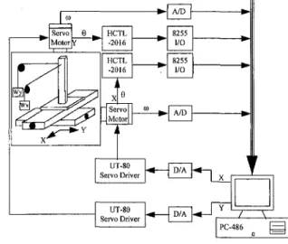
Fig. 5 Tiie experlmentai setup
implies the same magnitude M of the transfer function T; i.e., M = | r | = 11/(1 -I- CK)\, and each point on the inverse Nichol's Chart is the magnitude and phase frequency responses of the rational function CK{z)- Thus, the template of the rational function K{z) has to be moved into a suitable region by applying lead or lag compensators designed to keep the frequency response of the rational function CK{z) within the specified gain margin, phase margin and suitable gain response of the CETF in order to main-tain system stability and reduce contouring errors when the cross-coupling gains are changed.
V Implementation of the Robust CCC
The experimental setup for the present study is shown in Fig. 5. The PC-486 generated the main control commands and recorded the signals including: the input command calculation for different contours, the implementation of a variable-gain CCC controller, and the control inputs to the velocity loop. The Sanyo UT-80 DC servo driver with analog current signal feedback included a veloc-ity loop, a current loop, and a PWM output. The PC-486 interface utilized an AD/DA card to send and receive the control inputs and position outputs respectively at a sampling period of 1 ms.
The Position Loop. To identify the velocity loop for each axis,
the axial control input was given a pseudo random binary sequence (PRBS) and the systems were modeled as the ARX model (SQd-erstrom, 1989). Then, the equivalent digitally controlled plants (Pi, Pi), as shown in Fig. 2, for the present biaxial motion-control system were obtained as
P , ( z - ) = 0.0026Z"' -I- O.OOSz"^ + 0.0018?^' + 0.00222"" - 0.0003z ' + 0.0006z~'^ 1 - 1.5957Z'' -I- 0.5804Z-' - 0.322z""' + 0.30992"" -I- O . n O l z " ' - 0.20702-" + 0.1 I z " ' - 0.0456z' 0.0023Z"' + 0.0031z"^ + 0.0015z"^ - 0.0003z"" - 0.0036z"^ + 0.00032""^ 1 - 1.5578Z-' + 0.3473Z-' - 0.1946z"-' + 0.3141z" 0.1933Z- 0.102z-' + 0.1997z" 0.2001Z" (27) (28)
that the frequency responses of the rational function CK at certain reference frequencies satisfy the design specifications.
In consideration of the gain response of the CETF, the QFT design algorithm can be represented on the inverse Nichol's Chart. Each point on the same curve on the inverse Nichol's Chart
To achieve both stable motion and matched gains for the uncou-pled two-axis system (Poo et al., 1972), the position loop propor-tional gains {Kp^, Kp,) were set at
Magnitude (dB) - Phase (Degree) Table 1 Frequency responses of the robust CCC design M=0.1 - M~0.7O7_ Solid w=0.1 W-0.332S w=100 . ,w=1000
^r^
M=i^^— ^ . , , , , ^,1 . . ^ ,. . . ^ VJ-1.(10JM Dashed w=0.1 i w=0.3447 w=100 w=1000 I -50I
•* -100 -350 -300 -250 -200 -150 -100 -50 0 Phase (degree)Fig. 6 The frequency response of the rational function CK(ii with the Integral compensator C(2) ( : ( 0 , 1 , C,,i), : ( C a , 0,2))
K,,y = 0.2544
Compensator C Design. To maintain system stability and
achieve suitable CETF gain response, the conservative design specifications were set at a 50 dB gain margin, and a 90 deg phase margin. By applying the robust compensator design requirements (B1)-(B4) and the QFT design algorithm, the robust compensator was obtained as
C{z)
O.Sz" - 1.4625z' + 1.4713z^ - 0.5504z + 0.0417 z" - 1.0450z' + 0.04572^ - 0.0007z + 3 X lO"*'
(29)
To examine the system stability and the gain response of the CETF for different compensators, the frequency response of the rational function CK{z) with the digital integral compensator C{z) = l/(z - 1), a basic form in requirement B(l), was compared with the robustly designed compensator C{z), as in Eq. (29). We considered two linear commends of 79.38 and 13.24 degrees, respectively. Their corresponding cross-coupling gains {C^i, C,i) and (C,2, C,2) were (0.9829, 0.1843) and (0.2290, 0.9734), re-spectively. The frequency responses of ,the rational function
CK{z) for different compensators, C{z) = l/(z — 1) and C{z) as
in Eq. (29), with different cross-coupling gains are shown in Fig. 6 and Fig. 7, respectively. As shown in Fig. 6, the frequency responses of the rational function CK{ z) with the digital integral compensator C{z) = l/(z - 1) have both negative gain margins and phase margins, the cross-coupled system is thus unstable. As shown in Fig. 7, the frequency performance of all gain and phase margins for these gain variations are positive. Furthermore, the designed results listed in Table 1 for the two different linear
Magnitude (dB) - Phase (Degree)
M=0.1 MSDrTpT Solid w-0.1 w=0.3325 w-100 - w=1000 w=2473.6?71 M=1M-___
"" =wj-^°
1 )ashed »=0.1 »=0.3447 »=100 »=100O . »=1583.t698 -200 -150 Phase (degree)Degree of the line 79.38 13.24
(C,, C,) o),, (rad/sec) GM (dB) PM (degree) (0.9829,0.1843) 1.00232 1682.1172 51 90 (0.2290, 0.9734) 1.00268 1583.1698 50 90
commands meet the frequency response specifications well. More-over, the maximum gain of the CETF is only 1.00268 in the present CCC. Therefore, in addition to the guaranteed stability, the contouring error is also effectively suppressed by the present CCC design.
VI Experimental Results
Different Contouring Commands. Since the design of the
ro-bust CCC was based on linear contours, experiments were con-ducted involving three typical motion commands to verify its robustness:
(1) linear command: a linear command with 79.38 degree inclination angle, 20.3485 mm length at a speed of 1.2852 m/min for 0.95 seconds.
(2) corner command: a corner command is composited of two linear commands. The first linear segment of the corner command with 79.38 degree inclination angle, 20.3485 mm length at a speed of 1.2852 m/min for 0.95 seconds; the second linear command with 13.24 degree inclination angle, 21.8303 mm length at a speed of 1.31 m/min for 1 seconds.
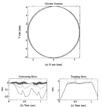
(3) circular command: a circular command was performed with a 6.25 mm radius at a speed of 1.9635 m/min for 1.2 seconds. We also compared the performance among three controllers, (1) an uncoupled controller with only a position loop controller P, (2) the proposed robust CCC, denoted as CCC(robust), and (3) a CCC in PID format, denoted as CCC(PID). We adopted the following parameters for the CCC(PID), Kp = 3.4, Ki = 6.2, and Kd = 0.11 which were obtained using the learning automata technique, spe-cifically, under the circular command (Chen, 1995).
Circular Contour
(a) X axis (ram)
Contouring Error Tracking Error
0.5 1 (c) Time (sec)
Fig. 7 robust
Fig. 8 Results for circular contouring, (a) Circular contour, (b) The The frequency response of the rational function CK{z) with the corresponding contouring error, (c) The corresponding tracidng error, compensator C{z) ( : (C,i, Cyi), : (C,2, Cyjj) ( : P -I- CCC(Robust), : P -H CCC(PID), : P)
Table 2 Experimental measures of linear contouring Error measure/controller P P + CCC(Robust) P + CCC(PID) Table 3 Experimental Error measure/controller P P + CCC(Robust) P + CCC(PID) Table 4 Experimental Error measure/controller P P + CCC(Robust) P + CCC(PID) lAE (mm) 7.7592 3.1001 10.6111 measures of corner lAE (mm) 59.4292 30.5961 61.7025 ISE (mm') 0.1832 0.0433 0.1548 contouring ISE (mm') 21.7336 12.6868 16.6428
measures of circular contouring
lAE (mm) 154.2828 54.8602 11.1431 ISE (mm') 24.9959 3.1295 0.1637
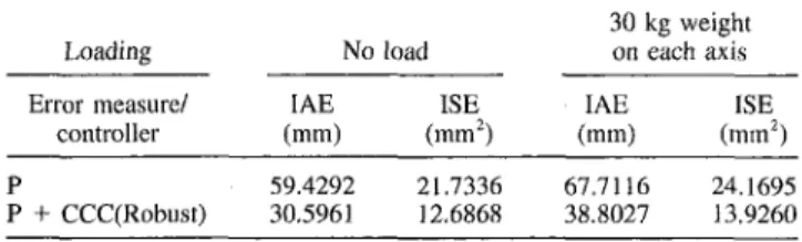
Table 5 Performance measures under loading for corner contouring Loading N o load 30 kg weight on each axis Error measure/ controller lAE (mm) ISE ( m m ' ) lAE (mm) ISE (mm') P + CCC(Robust) 59.4292 30.5961 21.7336 12.6868 67.7116 38.8027 24.1695 13.9260
Table 6 Performance measures under loading for circular contouring Loading No load 30 kg weight on each axis EiTor measure/ controller lAE (mm) ISE^ ( m m ' ) lAE (mm) ISE^ (mm') CCC(Robust) 154.2828 54.8602 24.9959 3.1295 190.4763 61.7682 45.1249 5.0257
Experimental results for the circular contouring command are shown in Fig. 8. Moreover, the normalized statistical results of corresponding integrals of absolute error (lAE) and integrals of square error (ISE), as listed in Tables 2-4, were also plotted, as shown in Fig. 9. Results indicate that compared with the uncoupled control system, the present robust CCC not only achieves signif-icantly improved contouring accuracy, but also maintains the ac-curacy over all contouring commands presented. Note that the CCC(PID), which was specifically tuned for circular motion did achieve the least circular contouring error, as shown in Fig. 9. However, it became oscillation when applied to linear and comer contours, because an optimally tuned CCC(PID) is only margin-ally stable. As a whole, results indicate that the present robust CCC rendered the best contouring accuracy over all commands pre-sented.
QP
• P-t-CCCIRobust)
• PtCCCIPID) Line Corner Circle
(a) lAE performance index
Loading Conditions. In practice, motion-control systems are
operated under either known or unknown loading conditions. Therefore, the present robust CCC design was also tested under a loading condition of 30 kg on each servo axis. The normalized statistical results for lAE and ISE for the corner and circular contours under loading, as listed in Tables 5-6. Results indicate that apparently, loading increased contouring errors in all cases. Nevertheless, the motion accuracy for the robust CCC still re-mained well even under different commands, as shown in Fig. 9. Clearly, the present design with sufficient stability margins makes the proposed robust CCC widely applicable.
VII Conclusions
This paper presents the theory and applications of a robust CCC design for motion-control systems. Based on a novel formulation of CETF, the design of the compensator C in the CCC is simply equivalent to a feedback-control design problem. Thus, available robust control theories can be applied to the proposed robust CCC design to achieve sufficient stability and contouring performance. For the present two-axis motion-control system, the CCC design is simplified to an SISO system and the QFT control design algo-rithm is directly employed to obtain satisfactory stability and guaranteed performance.
Experimental results indicate that the present robust CCC design achieves satisfactory contouring accuracy under different contour-ing commands and loadcontour-ing conditions. Although the robust CCC was designed with a fourth-order compensator in this case, the results provided by personal computer implementation have proven the feasibility of the present design.
a p
• PtCCCIRobust) • P+CCC(PID)
Corner Circle (b) ISE performance index
Fig. 9 Contouring errors for different compensators
References
Astrom, K. J., Hagander, P,, and Sternby, J., 1984, "Zeros of Sampled Systems,"
Autmnatica, Vol. 20, pp. 31-38.
Chen, F. 1., 1995, "Applications of the Learning Automata Method in Motion Control," Master thesis. Institute of Control Engineering, NCTU.
Chuang, H. Y., and Liu, C. H., 1992, "A Model Reference Adaptive Control Strategy for Improving Contour Accuracy of Multiaxis Machine Tools," IEEE Trans,
on Industry Application, Vol. 28, No. 1, pp. 221-227.
Chuang, H. Y., and Liu, C. H., 1991, "Cross-Coupled Adaptive Feedratc Control for Multiaxis Machine Tools," ASME JOURNAL OF DYNAMIC SYSTEMS, MEASURiiMENT, AND CONTROL, Vol. 113, No. 3, pp. 451-457.
Gotten, J., and Verwer, A., 1991, Control System Design and Simulation, McGraw-Hill.
Horowitz, 1. M., and Sidi, M., 1972, "Synthesis of Feedback Systems with Large Plant Ignorance for Prescribed Time-Domain Tolerance," /AT. J. Control Vol. 16, No. 2, pp. 287-309.
CNC Motion Control," CIRP Proceedings-Manufacturing Systems, Vol. 25, No. 1, Drive Servomechanisms," ASME JOURNAL OF DYNAMIC SYSTEMS, MEASUREMENT, AND pp. 91-96. CONTROL, Vol. 112, No. 2, pp. 225-232.
Koren, Y,, 1980, "Cross-Coupled Biaxial Computer for Manufacturing Systems," Kuo, B. C , 1992, Digital Control System, Saunders HBJ. ASME JOURNAL OF DYNAMIC SYSTEMS, MEASUREMENT, AND CONTROL, Vol. 102, No. 4, Ogata, K., 1970, Modern Control Engineering, Prentice Hall,
pp. 265-272. Poo, A., Bollinger, J. G., and Younkin, W., 1972, "Dynamic Error in Type Koren, Y., and Lo, C. C , 1991, "Variable Gain Cross Coupling Controller for Contouring Systems," IEEE Trans, on Industry Application, Vol. IA-8, No. 4, pp. Contouring," Annals of the CIRP, Vol. 40, pp. 371-374. 477-484.
Koren, Y., and Jee, S., 1995, "Fuzzy Logic Cross-Coupling Control," CIRP Soderstrom, T., and Stoica, P., 1989, System Identification, Prentice Hall.
Proceedings-Manufacturing Systems, Vol. 25, No. 1, pp. 104-108. Tomizuka, M., 1987, "Zero Phase Error Tracking Algorithm for Digital Control,"
Kulkarni, P. K., and Srinivasan, K., 1989, "Optimal Contouring Control of Mul- ASME JOURNAL OF DYNAMIC SYSTEMS, MEASUREMENT, AND CONTROL, Vol. 109, pp. tiaxis Drive Servomechanisms," ASME JOURNAL OF DYNAMIC SYSTEMS, MEASURE- 65-68.
MENT, AND CONTROL, Vol. H I , No, 2, pp. 140-148. Yeh, F. B., 1990, Post Modern Control Theory and Design, Eurasia Book Com-Kulkarni, P. K., and Srinivasan, K., 1990, "Cross-Coupled Control of Biaxial Feed pany.