Speed control of the 12-step sensorless drive for a brushless dc motor
Chih-Hsing Fang, Shir-Kuan Lin, Yu-Jheng Wu, and Chen-Kuo Lo
Citation: Journal of Applied Physics 103, 07E921 (2008); doi: 10.1063/1.2838230
View online: http://dx.doi.org/10.1063/1.2838230
View Table of Contents: http://scitation.aip.org/content/aip/journal/jap/103/7?ver=pdfcov Published by the AIP Publishing
Articles you may be interested in
Sensor-less pseudo-sinusoidal drive for a permanent-magnet brushless ac motor J. Appl. Phys. 111, 07E701 (2012); 10.1063/1.3669848
Design and control of a flux-controllable stator-permanent magnet brushless motor drive J. Appl. Phys. 103, 07F134 (2008); 10.1063/1.2838325
Design aspects of a high-speed sensorless brushless dc motor using third harmonic back-emf for sensorless control
J. Appl. Phys. 103, 07F110 (2008); 10.1063/1.2832618
Design of permanent magnet brushless motors with asymmetric air gap for electric vehicles J. Appl. Phys. 99, 08R322 (2006); 10.1063/1.2173615
Computer aided design of an axial-field permanent magnet brushless dc motor for an electric vehicle J. Appl. Phys. 93, 8689 (2003); 10.1063/1.1558595
[This article is copyrighted as indicated in the article. Reuse of AIP content is subject to the terms at: http://scitation.aip.org/termsconditions. Downloaded to ] IP: 140.113.38.11 On: Wed, 30 Apr 2014 23:10:45
Speed control of the 12-step sensorless drive for a brushless dc motor
Chih-Hsing Fang,1,a兲Shir-Kuan Lin,2Yu-Jheng Wu,2and Chen-Kuo Lo21
Division of Research and Design, Allis Electric Co., Ltd, 12F. No. 19-11, San-Chung Road, Nan Kang District, Taipei 115, Taiwan
2
Department of Electrical and Control Engineering, National Chiao Tung University, 1001 Ta Hsueh Road, Hsinchu City 30010, Taiwan
共Presented on 8 November 2007; received 28 September 2007; accepted 25 November 2007; published online 7 March 2008兲
The 12-step sensorless drive scheme requires an interval to detect the zero crossing of the back emf. The voltage regulating pulse-width modulation共PWM兲 is commonly used for the speed control of a motor. However, it induces the fluctuation of the back emf and makes the zero-crossing detection difficult. This paper proposes two digital approaches to the zero-crossing detection for the presence of the PWM. One approach is to vary the zero-crossing detecting period linearly with respect to the speed of the motor. The other is to detect the back emf only on the positive pulses of the PWM in order to avoid the fluctuation of the back emf. A digital filter is also incorporated in order to eliminate the noise generated by the PWM. Experiments show that both approaches have good performance for the speed control of the brushless dc motor. © 2008 American Institute of Physics. 关DOI:10.1063/1.2838230兴
I. INTRODUCTION
Recently, several sensorless drive schemes have been proposed for a brushless dc motor.1–3 Among them, Wang et al.3presented a novel 12-step sensorless drive scheme for a three-phase brushless dc motor, so that the active angular period can be extended from 120° to 168.75°. It has been shown that the larger the active angular period is, the larger is the torque generated by the motor. However, the detecting period for the zero crossing is fixed to 30 electrical degrees in the 12-step sensorless drive scheme. It results in the diffi-culty for the speed control of the motor, especially for low speed, since the duty cycle of the pulse-width modulation 共PWM兲 in the zero-crossing detecting period must be full. Shao et al.4presented analog circuit for the back emf detec-tion in the presence of the PWM.
To overcome this problem, this paper proposes two digi-tal approaches to the zero-crossing detection for the presence of the PWM. The first approach is to vary the zero-crossing detecting period linearly with respect to the speed of the motor. When the speed is slower, the electrical angle range for the zero-crossing detection shrinks, so that the time pe-riod for the zero-crossing detection is still almost the same for different speeds. Thus, the performance of the detection is not affected, while the PWM can work for a wide range of speeds.
An alternative approach is to detect the back emf only on the positive pulses of the PWM in order to avoid the fluc-tuation of the back emf. Such an approach can be easily implemented by a field-programmable gate array 共FPGA兲 chip. Moreover, it requires additionally a digital filter to eliminate the noise generated by the PWM.
II. 12-STEP SENSORLESS DRIVE
For simplicity, this paper considers only the 12-step 150° sensorless drive scheme, which combines the 120° and 180° drives. Between the electrical angles of 共30+60k兲 and 共60 + 60k兲 degrees, where k is a natural number, the motor ro-tates in the six-step 120° drive mode so that the zero-crossing points can be detected, while the 180° drive mode applies between the electrical angles of 共0+60k兲 and 共30 + 60k兲 degrees. This is illustrated in Fig.1. It is apparent that there are 12 steps in an electrical circle. The odd steps are the 180° drive mode, while the even steps are the 120° drive mode. It can also been seen in Fig. 1 that it lasts 150 elec-trical degrees before changing the polarity of one phase. There are two phase commutations for each zero crossing of the back emf:
• One is at the same time of the happening of the zero crossing共for the 180° drive mode兲 and
• The other is TZC共k兲/2 delay 共for the 120° drive mode兲,
a兲Author to whom correspondence should be addressed. Electronic mail:
ericf@allis.com.tw. FIG. 1. 共Color online兲 12-step 150° sensorless drive scheme. JOURNAL OF APPLIED PHYSICS 103, 07E921共2008兲
0021-8979/2008/103共7兲/07E921/3/$23.00 103, 07E921-1 © 2008 American Institute of Physics [This article is copyrighted as indicated in the article. Reuse of AIP content is subject to the terms at: http://scitation.aip.org/termsconditions. Downloaded to ] IP:
where TZC共k兲 is the interval time between the 共k
− 1兲th and the kth zero-crossing points of the back emf.
For the speed control, the dc load voltage is regulated by a switching transistor driven by a PWM signal, so that the load voltage is proportional to the duty cycle of the PWM. In Ref. 3 the zero-crossing detection period is fixed to be 15 electrical degrees. A direct extension to the speed control is to set this period having full duty cycle of the PWM, so that the zero-crossing detection is not affected by the PWM. However, low speed control will fail, since the dc load age is only partly controlled and is equal to the supply volt-age in the detection period.
III. VARYING-PERIOD APPROACH
LetZCbe the angular period of the zero-crossing
detec-tion共see Fig.1兲. First, the motor runs with the full duty cycle
of the PWM andZC= 15° to obtain the possible maximum
speed vM. Next, set the duty cycle as the unit duty cycle
共e.g., 2−11%兲 and
ZC= 1° to achieve the possible minimum
speed vm. The linearly varying-period relation of ZC to the
speedv is then
ZC= 1 ° +
15 ° − 1°
M−m
共−m兲. 共1兲
Two cascade proportional integral共PI兲 controllers form the speed control scheme of the motor with the 12-step 150° sensorless driver, as shown in Fig.2. The inner PI loop is for the current control and is incorporated with an antiwindup strategy. Its output vlgenerates the duty cycle of the PWM.
The antiwindup PI controller can be written as5
l=l+ Kcieits+ Kcp共ei− ia兲, 共2兲
where ei= i − i*, tsis the sampling time and iais the output of
the antiwindup. The compensation value ia is the result of FIG. 2.共Color online兲 Speed control block diagram of a BLDC motor.
FIG. 3.共Color online兲 Speed responses for the varying-period zero-crossing detection:共a兲 without the antiwindup; 共b兲 with the antiwindup.
FIG. 4.共Color online兲 Voltage histories of the three phases for the varying-period zero-crossing detection:共a兲 5000 rpm; 共b兲 1000 rpm.
07E921-2 Fang et al. J. Appl. Phys. 103, 07E921共2008兲
[This article is copyrighted as indicated in the article. Reuse of AIP content is subject to the terms at: http://scitation.aip.org/termsconditions. Downloaded to ] IP: 140.113.38.11 On: Wed, 30 Apr 2014 23:10:45
multiplying the excess of vl over the saturation limit 共e.g.,
211兲 with the gain K
a.
A brushless dc共BLDC兲 motor used as a spindle motor of a 50⫻ CD-ROM is taken as an experimental target. The speed control algorithm is implemented on an FPGA chip with 50 MHz. The carrier frequency of the PWM is set as 50/211= 0.0244 MHz. It is found that v
M= 5500 rpm and
vm= 180 rpm. The histories of the speed responses without
and with the antiwindup are shown in Fig3. The responses for the controller without the antiwindup have fluctuations, especially for low speed commands. This is because the out-puts of the controller touch the bound several times. On the contrary, the controller with the antiwindup has very good performance. It is also verified that the linearly varying zero-crossing detection period is effective for the speed control. Figure 4 shows, furthermore, the voltage histories of the three phases for the speed commands of 5000 and 1000 rpm. It is easy to see the full duty cycle intervals for the zero-crossing detection; 14.1° for 5000 rpm and 3.6° for 1000 rpm.
IV. DIGITAL FILTER APPROACH
The approach without interrupting the PWM signals is to detect the back emf only on the positive pulses of the PWM. This approach is hard to implement on a DSP or a micropro-cessor; but is easy on an FPGA chip, since a FPGA handles all processes including the PWM in the pace of the system clock. This approach utilizes the following techniques:
• A synchronization mechanism with the PWM provides the start and the end of each positive pulse of the PWM. The zero-crossing detection is performed only in the intervals of the positive pulses.
• Two stages of digital filter are applied. One is a delay of two system clocks from the start of a positive pulse before detecting the zero crossing. The other stage is a noise elimination filter, which records consecutive re-sults of the comparator of the back emf with the neu-tral voltage for five system clocks. If five consecutive results are all true, the zero crossing occurred five sys-tem clocks ago.
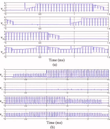
The histories of the speed responses with the digital filter for the zero-crossing detection are shown in Fig.5. It is of no doubt that the resulting performance is satisfied. The over-shoots are even a little less than those in the varying-period approach. The voltages of the three phases are recorded in Fig.6, which show that there are some noises in the positive pulses.
V. CONCLUSIONS
This paper proposes two digital approaches to the zero-crossing detection for the presence of the PWM. An anti-windup PI speed controller incorporated with one of these two approaches has been proved well suitable for the speed control of a BLDC motor with the 12-step sensorless driver. Experimental results also show the voltage behaviors of the three phases during the speed control.
ACKNOWLEDGMENTS
This work was supported by the National Science Coun-cil, Taiwan under Grant No. NSC 95-2221-E-009-101.
1J. P. Johnson, M. Ehsani, and Y. Guzelgunler, Proceedings of the Industry Application Conference, 1999共unpublished兲, pp. 143–150.
2J. Shao, D. Nolan, and T. Hopkins, Proceedings of the 17th Annual IEEE APEC, 2002共unpublished兲, pp. 33–37.
3C. M. Wang, S. J. Wang, S. K. Lin, and H. Y. Lin, IEEE Trans. Magn. 43, 2555共2007兲.
4J. Shao, D. Nolan, and T. Hopkins, IEEE Trans. Ind. Appl. 39, 1734 共2003兲.
5G. F. Franklin, J. D. Powell, and A. Emami-Naeini, Feedback Control of Dynamic Systems共Prentice-Hall, New Jersey, 2002兲.
FIG. 5.共Color online兲 Speed responses for the zero-crossing detection with the digital filter.
FIG. 6. 共Color online兲 Voltage histories of the three phases for for the zero-crossing detection with the digital filter:共a兲 5000 rpm; 共b兲 1000 rpm.
07E921-3 Fang et al. J. Appl. Phys. 103, 07E921共2008兲
[This article is copyrighted as indicated in the article. Reuse of AIP content is subject to the terms at: http://scitation.aip.org/termsconditions. Downloaded to ] IP: 140.113.38.11 On: Wed, 30 Apr 2014 23:10:45