國
立
交
通
大
學
資訊科學與工程研究所
碩
士
論
文
無 校 正 影 片 中 多 材 質 物 體 深 度 之 重 建
Image-based Depth Reconstruction of Multi-material
Objects from Uncalibrated Video
研 究 生:顏志翰
指導教授:林奕成 助理教授
由無校正影片中多材質物體深度之重建
Image-based Depth Reconstruction of Multi-material Objects from
Uncalibrated Video
研 究 生:顏志翰 Student:Zhi-Han Yen
指導教授:林奕成 Advisor:I-Chen Lin
國 立 交 通 大 學
資 訊 科 學 與 工 程 研 究 所
碩 士 論 文
A ThesisSubmitted to Institute of Computer Science and Engineering College of Computer Science
National Chiao Tung University in partial Fulfillment of the Requirements
for the Degree of Master
in
Computer Science
January 2009
Hsinchu, Taiwan, Republic of China
無校正影片中重建多材質物體深度
研究生:顏志翰
指導教授:林奕成 助理教授
國立交通大學
資訊科學與工程研究所
摘要
本論文提出一個能從影像序列中還原物體表面演算法,以應用在三維顯示器 中。針對單一方向光源環境,我們能還原多材質和非剛體物體表面。還原真實物 體表面一直是很難的課題,shape-from-shading 和 multiple-view 是最常使用 的技術。但是 shape-from-shading 只能處理單一材質且表面連續的物體, multiple-view 則無法保留較細微的表面,同時也需要耗時的配對對應點。因此, 我們結合 shape-from-shading 和 non-rigid structure-from-motion 的技術 來重建更細微完整的表面.關鍵字:shape-from-shading、non-rigid structure-from-motion、多材質
Image-based Depth Reconstruction of Multi-material Objects
from Uncalibrated Video
Student: Zhi-han Yen Advisor: Dr. I-Chen Lin
Institute of Computer Science and Engineering
National Chiao Tung University
Abstract
In this thesis, we propose a method to reconstruct real object in a video sequence which can be used for the 3D display. Under a single directional lighting condition, the target object can be multi-material、non-rigid. Shape recovery of real object from a video sequence is a difficult subject. Shape-from-shading and multiple-view technique are the most common methods. Shape-from-shading can only deal with single-material smooth objects. The multiple-view technique acquires the point clouds without the surface detail and needs time-consuming correspondence matching. For these reasons, we combine shape-from-shading and non-rigid structure-from-motion techniques to reconstruct more detailed surfaces.
Keyword :
shape-from-shading 、 non-rigid structure-from-motion 、 multi-materialAcknowledgements
First of all, I would like to thank my advisor, Dr. I-Chen Lin, for his guidance in the past two years. Also, I appreciate all members of Computer Animation & Interactive Graphics Lab for their help and comments. Finally, I am grateful to my family for their support and encouragement.
Contents
摘要……….I ABSTRACT………..II ACKNOWLEDGEMENTS……….III CONTENTS……… IV LIST OF FIGURES………...V CHAPTER 1 INTRODUCTION………...1 1.1BACKGROUND……….…..1 1.2FRAMEWORK……….3 1.3CONTRIBUTION……….4CHAPTER 2 RELATED WORK………...5
2.1STRUCTURED LINE………...5
2.2MULTIPLE VIEW………6
2.3PHOTOMETRIC STEREO……….8
2.3SHAPE FROM SHADING……….10
CHAPTER 3 Multi-Material Shape from Shading Reconstruction……….11
3.1 First Phase – Multi-Material Shape from Shading……….12
3.1.1 Super-pixel Clustering……….…12
3.1.2 Propagating Intensity Offset between Super-pixels………13
3.1.3 Shape from Shading Shape Recovery……….15
3.2 Second Phase - Non-rigid structure from motion………..19
3.3 Third Phase - Combination with space time constrain………..…20
3.3.1 Spatial constraints………...20
3.3.2 Combination with shape-from-shading and structure-from-motion...21
CHAPTER 4 Experiment and Result………...22
4.1 The Experiment of Input Video Sequence………..22
4.2 The Reconstructed Surface Detail………..24
CHAPTER 5 Conclusion……….30
CHAPTER 6 Future Work……….30
REFERENCE………...31
List of Figures
Fig1……….5 Fig2.. ………..6 Fig3.. ………..6 Fig4.. ………..7 Fig5……….7 Fig6……….7 Fig7……….8 Fig8……….9 Fig9……….9 Fig10……….10 Fig11……….11 Fig12……….11 Fig13……….12 Fig14……….13 Fig15……….14 Fig16……….14 Fig17……….16 Fig18……….17 Fig19……….18 Fig20……….20 Fig21……….21 Fig22……….23 Fig23……….23 Fig24……….24 Fig25……….25 Fig26……….25 Fig27……….26 Fig28……….27 Fig29……….28 Fig30……….29 V1
Chapter 1 Introduction
1.1Background
Televisions are more and more important in every family. They bring not only information but also entertainment to us. In recent years, there are dramatic improvements with them, especially in size and resolution. Even though, people still gradually unsatisfy with the traditional fixed viewpoint 2D display gradually and want to have more variety. Therefore, it becomes the current trend developing free viewpoint 3D display. Generally speaking, the modern 3D display technique can be categorized as stereoscopic display and auto-stereoscopic display. No matter what technique they use, the depth map of each frame used to specify objects near or far is always necessary.
There are many methods to generate depth maps, and it‟s the prevailing one by using multiple views which need synchronous image capture and pixel-based correspondence matching in each view. Due to the scene complexity(not-rigid body、 similar color object、occlusion), it‟s really a challenge to recover depth map by the multiple-view technique. Even though, by adding some human assistants, multiple views can still get a more effective result. However, our popular –used videos, like existing DVD movies, were not captured by the multiple views technique, the view-points are uncalibrated and they are difficult for precise frame-by-frame correspondence matching. For these reason, we want to find out a suitable and practical approach such that we can generate sequence of depth map toward the target object from the common video sequence.
Other methods ,like shape from shading(SFS)、structure from motion(SFM) and photometric stereo are also important for shape reconstruction. Photometric stereo use multiple images taken with a fixed viewpoint and different lighting conditions to recover the shape and reflectance properties of the target object. Although this method
2
can reconstruct a detailed surface, it‟s limited only for Lambertian surface object. SFM is a technique similar to multiple-view technique but uses only one camera and views from camera motion instead. It recovers the point cloud and projection matrix from the correspondences in the frames but not as accurate as the calibrated multiple views technique. SFS technique recovers the depth of the object in the image via the comparison of its intensity variation and reflection model. The advantage of SFS is that it requires only one image and can avoid pixel correspondence problem. In spite of these advantages, SFS has several limitations, for instance, it‟s sensitive to the noise of intensity, and the light condition is limited to single light source or simple light conditions. SFS techniques are only for single material object by its principle.
Our goal is to recover the depth maps of target objects from a general purpose video sequence like movies or family video illuminated at a simple lighting condition .Because the target object in the video sequence can be of multi-material or non-rigid-body properties, we combine the SFS and the non-rigid SFM with space-time optimization to approximate its surface as real as possible.
3
1.2Framework
First Phase Second
Phase
Feature Point Extraction Super-pixel Clustering
Non-Rigid Structure from Motion Video Sequence Target Object Segmentation Boundaries of Multi-Material Segments Adjust
SFS and Reflectance model recovery Optimization between non-rigid SFM and SFS Space-time optimization Output Depth map sequences Third Phase
4
Our goal is to recover the shape of target object in one video sequence. As the flowchart above, we instead to a segment of video sequence and generate the corresponding depth map sequence. The system can be split into four parts.
In the first part, we take one video sequence as input and segment the target object frame by frame. The target object may be a non-rigid object like cloth or rigid object like a rolling ball, etc. We assume the light condition is directional spot lighting or in a cloudy day.
In the second part, toward the target object, we extract the time-varying feature points frame by frame and recover shapes b structure from motion, a technique of reconstruction without calibration, especially useful for common video.
In the third part, with the over-segmentation of a target object with continuous surfaces, we find out the boundaries of different materials and adjust height of intensities between them. After the offset propagation along boundaries of segments, we can interactively approximate the 3D shape and the reflectance model.
In the fourth part, we combine SFS with SFM. For the sake of more reliable and continue 3D points, we add the space-time optimization between neighboring frames.
1.3Contribution
In this thesis, we propose an approach to recover the shape of the target object on a video sequence. The object can be a moving、non-rigid-body or with multiple-reflectance properties. To improve the reliability, we add the spatial and temporal coherence constrain. The primary contributions are as follows:
(1)An advanced shape from shading technique toward the multi-material object is proposed.
(2)Toward the real object in the video sequence under a single directional light condition, we can produce a temporal-consistent depth maps for display on 3D TV.
5
Chapter 2 Related Work
There are four kinds of methods for 3D reconstruction. The first approach(Fig1) is interactive modeling with manual assistance, like Blender3D、 Maya. We can build a model manually, but it is difficult and time-consuming to create a photorealistic result. Several intelligent or hybrid modeling system were proposed to reduce manual intervention. Anton et al.[1] proposed building a realistic 3D models from video by point clouds with a small number of simple 2D sketches as constraints.
Fig1. Left to right: a frame from the input video sequence, a partial tracing of the model, the final model overlaid on the video, and the result of rendering the final model back into the original sequence.
2.1 Structured-line
By contrast, the second kind of approach using active structured light system is faster and more convenient (Fig2). It is also the main stream of the high-accuracy 3D recovery. In the early years, 3D scanning technique is only suitable for static objects, and it needs more scanning time. S.Rusinkiewicz et al. [2] develop the system based on the structured-light system and a real-time variant of ICP(iterative closest points) to align the shapes acquired from multiple views. It makes the significant effect of rapid 3D recovery.
6
In addition, L.Zhang et al. [3] use the consistent space-time stereo technique to enhance the reliability of acquired 3D data (Fig3).
Fig3. L.Zhang et al‟s facial detail reconstruction system and depth data
By use of the structure-light system, we can precisely estimate the shape of the
target object, but it still has several defects limiting its usability. The target object is
limited to be a nearly-lambertian object and not suitable for the one too big or the
scene outdoors.
2.2Multiple views
Multiple view technique plays an important role in reconstruction. With the calibration and correspondence mating, we can reconstruct scene‟s surface without limit. But it‟s cost-high to find the reliable correspondence matching and the occlusion of correspondences are also the problem. Even though, it‟s still widely used as constrain to other technique or a coarse shape recovery.
Vogiatzis et al. [4] proposed a novel technique combined multi-view stereo with Fig2. S.Rusinkiewicz et al‟s real time structure-line system and the reconstruction data
7
Graph-cuts optimization for detailed surface reconstruction (Fig4). They use the visual hull as the initial shape, and then define a continuous photo-consistency function as a flow graph to minimize the detailed surface.
Structure form motion is a technique use only one single camera and suitable for the moving rigid or static object. With the uncalibrated property, it‟s very suitable for the common video sequence although it‟s not as precisely as calibrated multiple views techniques.
Pollefeys et al. [5] use the corner detection to find out the feature points, and then find out the correspondences by use of the epipolar geometric properties. The affine transformations between multiple-views are therefore acquired (Fig5).
If there are fewer correspondences, there may be discrete 3D points. For this Fig4. Vogiatzis et al„s detailed surface reconstruction
Fig5. Reconstructed model and the view points
Fig6. Textured point cloud by quasi-dense approach
8
reason, M. Lhuillier et al. [6] proposed a approach to generate quasi-dense 3D points toward the surface with fewer feature points (Fig6). They produced a dense disparity map and use it to improve numbers and qualities of the feature correspondences matching by the correlation method. Moreover, they proposed a fast gauge-fee algorithm to estimate the accuracy of the recovered 3D depth.
For the non-rigid body, Lorenzo et al. [7] proposed a method combined with structure from motion to recover the target shape from the video (Fig7). They defined a non-rigid body as a rigid transformation combined with a non-rigid deformation in the time frames. Under the assumption that the object shape at each time frame is organized from a Gaussian distribution, they simultaneously estimated 3D shapes in each time frame, learned the parameters of the Gaussian, and also recovered the missing data points. Finally, they implement the space-time constrain to the object shape for the better consistent result.
2.3 Photometric stereo
Photometric stereo estimates local surface orientation by using several images of the same surface taken from the same viewpoint but under illumination from different directions.
Fig7. Reconstructions of the shark sequence using Lorenzo et al‟s method. It‟s given 2D tracks as inputs; reconstructions are shown here from a different viewpoint.
9
M. seitz et al. [8] proposed the example-based photometric stereo method (Fig8). They introduced orientation-consistency concept to reconstruct the surface normal from the reference images where the reference objects with idential materials are also taken. Combined with traditional photometric stereo, there will be a more detailed surface recovered. The technique is extremely simple to implement to a broader class of objects than previous photometric stereo technique. Fig. 4(a) shows the bottle result of the 3D recovery. Fig 4(b) illustrates images with different light source directions.
Carlos et al. [9] used the silhouettes in multiple views to recover camera motion and then got a coarse shape of the object by the visual hull (Fig9). Besides, they proposed a robust technique to estimate light directions and introduced a novel formulation to combine photometric stereo and 3D points from visual hull.
Fig8. The left two images are the reconstructed surface by the seitz et al‟s method The right four images are the reference and target object used for
reconstruction
Fig9. Detailed surface reconstructed by Carlos et al‟s photometric method
10
2.4Shape from shading
Shape form shading recovers the shape from the gradual variation of shading of one single image. It‟s difficult for real applications due to its intrinsic ill-pose problem. Besides, it‟s limited to be the Lambertian reflectance model and single light condition. Even though, it is still an important topic in computer vision for it advantages. We need only one single image and without the time-wasting correspondences matching compared to multiple views technique. For this reason, there are still many surveys or applications with it.
Due to its intrinsic ill-pose problem, Zeng at al. [10] proposed a global solution of continuous surface. Users input surface normal on specific feature points and the system refines the surface variations to the whole face (Fig10). This method applied a Fast Marching Method which speeded up the computation to the divided local patches, and each local surface is estimated with some human assistances. After optimizing the energy function combining with each local surface, it can evaluate a global solution toward synthetic and real-world data.
Tai-Pang ea al.[11] made a extension of the above one(Fig11). Toward the biases of the light direction, they reformulated SFS and produce good initial normals for a large region to leave most noticeable errors mainly in the smooth part. They also
11
developed an easily used 2D user-interface to edit and correct the normal map toward noticeable errors.
Fang et al.[12] combined the shape-from-shading and texture synthesis to re-texture the target object in the photograph(Fig12). However, this approach is error-prone due to the Lambertian surface assumption and simple lighting conditions. It‟s only suitable for some simple objects, like t-shirt or sculptures, and need manual rectification.
.
Chapter3 Multi-Material Shape from Shading Reconstruction
This thesis focuses on the reconstruction of a target object in the video sequence under a single directional light condition. Reconstruction on a real object is always a difficult subject. Although the multiple-view technique can lead to the more precise 3D positions, it still needs time-consuming and accurate pixel correspondence and lots of image inputs. The photometric stereo technique also needs the specific controlledFig11. Tai-Pang et al‟s reconstructed surface
Fig12 Left: input image; middle: estimated normal map; right: textured surface
12
light direction which is not suitable for the common video sequence due to its multiple unknown light direction. Furthermore, they cannot both deal with the not-rigid body and the uncalibrated video sequence. For these reasons, we propose using a novel hybrid methods which can recover 3D surfaces combining the non-rigid structure-from-motion and multi-material shape-from-shading.
3.1 First Phase – Multi-Material Shape from Shading
Conventional Shape-from-shading technique is only suitable for the target object composed of only one material (consistent reflectance property)but a common object surface usually have multiple reflectance properties. For this reason, we will divide the image inputs into spatially connected segments and each segment has only a single material. By the segmentation, we can perform the SFS to each single material segment. But SFS is the technique based on the optimization of intensity and reflectance model. There will be some artifacts between the boundary of each segment. At the next step, we will adjust the boundary between each segment and propagate the offset between them to generate an intensity map with smooth boundaries. As we acquire the final smooth intensity map, we can get a surface without artifacts at boundaries. The detailed steps are introduced bellow.
3.1.1 Super-pixel Clustering
To avoid the artifacts between boundaries of different materials due to the intensity difference, we split the target object into multiple single material segments, and each one are spatially connected (Fig13).
13
“Super-pixels” [13] is the technique we use. It‟s a clustering technique based on Normalized Cuts. It exploits pair-wise brightness, color and texture cues between pixels to over-segment images into multiple spatially connected components. This technique accelerates region clustering and edge finding operations. With the super-pixel clustering, we can not only preserve spatial relationship between segments but also find out the boundaries between different materials as the picture shows above more easily.
3.1.2Propagating Intensity Offset between Super-pixels
As other clustering technique‟s limit, super-pixel technique can‟t find the perfect boundary between different materials (Fig14). It‟s due to the trade-off of position and intensity differences in objective functions. If we don‟t find out the precise boundary, our system further provides offset propagation to eliminate boundary artifacts.
To improve the boundaries by super-pixel, we use the shortest path method to align the boundary according to intensity gradients. After we generate a small gradient map around the specific boundary and readjust the boundary, we re-distribute the pixels around the boundary belong to the two neighbor super-pixels. Repeat this step, we get more and more precise boundaries. Although the aligned boundaries are closer to the material boundaries, the intensity difference at the boundary is not yet
Boundary Adjusts between Super-pixels
Super-pixels offset propagation
Smooth filter
14
eliminated. For this reason, we compensate the super-pixels offset to complete a smooth and continue intensity map.
At first, we choose one super-pixel as the start seed and then shift the neighbor super-pixels in the intensity domain. After we offset the neighbor super-pixels, they will be connected smoothly in the intensity domain. The neighbor super-pixels‟ offset can be split into two parts- boundary and internal parts(Fig15、Fig16). In the boundary part (Fig15), the offset is the difference from intensity of boundary pixel in the start super-pixel to the closest pixel in the neighbor super-pixel. To avoid noise, we average regional pixels around the boundary pixels and then take the result to the offset operation.
In the internal part (Fig16), we interpolate the offset values according to the distance to the boundary.
Fig15. Boundary part
15
Afterwards, we propagate offset operation to all super-pixels and then acquire a smooth connecting intensity map without the fault due to the boundary of different materials. Although we make this propagation, there may be still some artifact in the boundary in the final intensity map. To solve this problem, we repeat the propagation to get a better result or simply use the other smooth filter. Once we acquire a satisfying intensity map, we start our shape recovery by use of the following shape-from-shading technique.
3.1.3 Shape from Shading Shape Recovery
Our thesis is based on [13] for the basic shape and light condition recovery. The method in [13] recovers only the single material object, and we extend to the multiple material object. Therefore, we take the shape-from-shading technique to the final intensity map and use space-time constraints as the final smoothness. According to the surface intensity variation and the spatial and temporal coherence, we can recover the 3D data based on the optimization method.
Let V denotes the set of shape parameters. In order to decrease the dimensions of the cost function, we represent the 3D data in terms of height maps, and therefore, we only have to optimize the z values. Hence the set of shape parameters V can be defined as:
V
{
z
i}
i
1~ point number (1)Our reflectance model is Phong model, since it is widely used in the computer graphics and parameters can be efficiently acquired. Given a light source L and the surface normal N, the Phong reflection model can be written as:
)
)
(
)
(
(
|
|
L
K
L
N
K
e
r
I
d
s
(2)16
Phong exponent term. The vector
e
denotes the eye direction andr
is the reflection vector at the mirror direction of the light source with respect to the surface normal.Let R denotes the reflectance parameters which can be defined as:
R={Kd, Ks ,α } (3) Our cost function
C
can be defined as the sum of the square error between the input real imageI
and synthesis imageS
,
C
V
R
I
S
V
R
i
number
of
pixel
i i i(
,
))
1
~
(
)
,
(
2
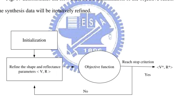
(4)Fig. 17 demonstrates the flow chart of the minimization of the objective function. The synthesis data will be iteratively refined.
Refine the shape and reflectance parameters < V, R >
Objective function
Reach stop criterion
Yes
No
<V*, R*>
Initialization
Figure 17: The flowchart of the minimization of the cost function
In other words, our goal is to find the shape and reflectance parameters
V ,
R
that will minimize the cost function:)}
,
(
min{
arg
*
*,
R
C
V
R
V
(5) Our cost function has two sets of parameters, the shape parameters V and17
reflectance model parameters R. The parameters R is the global parameters for all the triangle facets but the parameters V represent only local geometry. If we refinement these two parameters into a single optimization procedure, we should choose the proper scales of the two kinds of parameters to balance the effects. In order to avoid unbalance condition, we optimize these two parameters separately to obtain the more accurate result. The flow chart of the optimization method is showed below,
3D shape parameters V Reflectance model parameters R Initial shape < V , R >
Initial reflectance parameters
Figure18: Flow Chart of the optimization algorithm
First, we assign the initial shape and reflectance parameters to this system. Different initial conditions will influence the optimization results. We can adjust the parameters manually or apply the batch work. Afterward, the reflectance parameters will fix and the shape parameter V is refined.
In order to optimize the initial shape more reliably, we just apply the diffuse model in the first phase. Specular terms will be included on the following phases. After optimizing the shape parameters, the reflectance parameters R will be refined while the optimized parameter V is fixed. We will repeat these steps until the cost value is small than the threshold.
We treat the minimization of the cost function as a non-linear least square problem and solve its solution by the conjugate gradient method.
18
According to the conjugate gradient, the cost function should be differentiated by the variable of shape parameters V,
V
S
I
V
C
i i i
(
)
2 (6)Expanding the function becomes
2
))
)
(
)
(
(
(
V
r
e
K
V
N
L
K
V
I
V
C
s i d
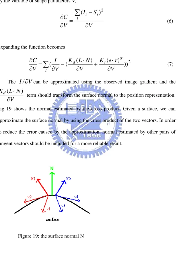
(7)The
I
/
V
can be approximated using the observed image gradient and theV
N
L
K
d
)
(
term should transform the surface normal to the position representation. Fig 19 shows the normal estimated by the cross product. Given a surface, we can approximate the surface normal by using the cross product of the two vectors. In order to reduce the error caused by the approximation, normal estimated by other pairs of tangent vectors should be included for a more reliable result.
19 The
V
r
e
K
s
(
)
term can also be evaluated in the same way, but the
reflection vector should be represented in term of N, L:
L
N
r
2
(8) In order to acquire more accurate results, we only adjust the z component to reduce the dimension of the optimization function.Our reflectance parameters
R
{
K
d,
K
s,
}
can also be computed by finite differencing as the shape optimization. In general, we normalized the parameters of Phong model and assumeKd Ks 1.3.2 Second Phase - Non-rigid structure from motion
By use of shape-from-shading, we can acquire a detailed surface. However, the surface from SFS is relative depth, not the absolute depth like structure-from-motion. Furthermore, shape-from-shading recovers surface by frames in temporal domain and can‟t deal with occlusion or correspondence problem. For those reasons, we take structure-from-motion as constrains for more accurate single frame recovery and other cues for temporal coherence. In general, structure-from-motion is technique for rigid body and uncalibrated video but can‟t deal with the occlusion problem. We take the improved structure-from-motion [15] at high textural features to improve surfaces recovered by shape-from-shading. This method models shape motion as a rigid component (rotation and translation) combined with a non-rigid deformation and assumes that the object shape at each time instant is formed from a Gaussian distribution. We use this method to recover the specific points of the non-rigid body, and therefore build the relationship of temporal coherence for shape-form-shading which will be specified at the next section.
20
3.3 Third Phase - Combination with space time constrain
After we recover the detailed SFS surface and accurate discrete SFM points. We combine them into a complete and precise surface. However, there will be too much noise, since every time-varying depth map is acquired independently and temporal flicker may occur between consequent frames. In order to solve this problem, we add the spatial and temporal constraints to obtain the more reliable result.
3.3.1 Spatial constraints
For a smoother surface, we propose the space-time shape-from-shading to recover the 3D data. To stabilize the iterative shape-from-shading and to obtain reliable result, we use a spatial constraint as
Z x y Z Neighbori dxdy Spatial win i 2 1 ] )) ( ( ) , ( [ (11)Neighbor(i) denote the ith neighbor pixels of Z(x , y). Adding the spatial constraint
will smooth the depth value.
21
3.3.2 Combination with shape-from-shading and structure-from-motion
Non-rigid Structure-from-motion we take can only recover the specific feature points at each frame. By use of the specific points at shape-from-shading corresponding to those at structure from motion, we build the transformation between the SFS and SFM, and then transform the all recovered 3D points at SFS to the SFM. However, because of SFS‟ intrinsic ill-posed problem, the recovery is not good enough. For this reason, we take the acquired depth as the initial guess to repeat the flow above. We can recover a more precise shape with the combination of shape-from-shading and structure-from-motion (Fig21). The SFM constrain is bellow.
(9) points specific ) , ( , ) , ( )) , ( ( ( 2
T Z x y M x y dxdy x y SFMFig21. Flowchart of Combination with SFS and SFM
Optimize SFS with SFM constrain Output: depth map of each frame Input1:3D points recovered from SFS Input2:3D points recovered from SFM 3D points combined with SFS and SFM Transformation matrix from SFS to SFM
Initial depth used for SFS recovery
Least square Optimization Specific points recovered by SFS Specific points recovered by SFM RBF of 3D points from SFM
22 T is the transformation of specific points from SFS to SFM; M is the depth of specific points relative to the transformed SFS plane. Finally, we conclude SFS optimization combined with SFM as bellow.
(10) ] ) R) (V, ( [ ) , (V R I S 2 spatial SFM dxdy C
Chapter 4 Experiment and Result
In this chapter, we describe our experiment and show our result. At the beginning, we introduce the experiment of the input video sequence. Then, we will show the final results where the structure-from-motion and intensity propagation are included.
4.1 The Experiment of Input Video Sequence
In our system, we use one video sequence to create the depth maps. In order to acquire the more accurate surface details, our input images are taken under a restricted light environment, where only one directional light is applied.
We set a projector as the single light source. Our input data are the two synchronized high-definition video (HDV, 1280*720 pixel resolution) and the frame per second (FPS) is set to the 30 frames per second. In order to increase the efficiency, we decrease the size of the video to 240*120.The three figs bellow shows the three different views of the video sequence.
23
Fig22. Three different views from the video sequence.
We pick a set of apparent feature points at the surface of the object as the specific points (Red points Fig25).
Fig23. Picked specific points
In our research, we apply a novel temporal shape-from-shading combined with SFM to reconstruct the 3D shape. At first, we utilize an optimization method [13] to solve the ill-condition of shape-from-shading. This method can optimize the space
24
and reflectance parameters to minimize the cost function. Afterwards, we use the offset propagation to reduce the boundary artifacts. This method can reduce the depth offset between multiple materials and make the reconstructed surface smooth. The progress is showed bellow.
(a) Original image (b) Original intensity
Fig24.
Offset propagation effects
4.2 The
Reconstructed Surface DetailAfter we acquire the satisfied intensity map, we continue the optimization of SFM for more accurate and detailed surface. The Figs bellow shows the effects of the offset propagation and SFM constrain. With the offset propagation, the surface artifact between the boundaries of the materials can be eliminated. With the SFM, the detailed more accurate surface can be acquired.
25
Fig25. Original Image
26
27
28
29
30
Chapter 5 Conclusion
In this thesis, we propose an improved space-time shape-from-shading to reconstruct the surface of multi-material object. We utilize the offset propagation to recover the surface of multi-material object to improve the original SFS (suitable only for single material). We also apply the optimization method combined with the non-rigid SFM for the more detailed surface recovery. Finally, we apply the temporal constrain for the final optimization in order for one smooth depth sequence suitable for the 3D display.
Our method is limited for the simple light condition and toward the smooth object.
Our contribution include
(1) A novel space-time shape-from-shading for recovering 3D data (2) Reconstruct more detailed surface toward the multi-material object (2) Reconstruct more detailed surface toward the rigid or non-rigid object
Chapter 6 Future Work
In this thesis, we adopt Phong model as the reflectance model. Other reflectance models such that Torrance model or BSSRDF which has more physical cues may get more accurately results. And the other hand, we can apply other numerical method such that Fast Marching Method (FMM) to speed up the optimized procedure.
31
Reference
[1] Anton van den Hengel, Anthony Dick, Thorsten Thorm¨ahlen, Ben Ward, Philip H. S. Torr,” VideoTrace: Rapid interactive scene modeling from video”, SIGGRAPH‟07 [2]Szymon Rusinkiewicz Olaf Hall-Holt Marc Levoy, ”Real-Time 3D Model Acquisition”, ACM TOG‟02.,
[3] L.Zhang, N. Snavely, B. Curless, S.M. Seitz, “Spacetime Faces: High Resolution Capture for Modeling and Animation”, SIGGRAPH‟04.
[4]G. Vogiatzis, P. H. S. Torr, R. Cipolla,” Multi-view Stereo via Volumetric
Graph-cuts”, CVPR‟
[5]G. Vogiatzis, P. H. S. Torr, R., ” Volumetric graph-cut”, CVPR'05
[6]Maxime Lhuillier, Long Quan, “A quasi-dense approach to surface reconstruction from uncalibrated images”, PAMI‟05
[7]Lorenzo Torresani, Aaron Hertzmann,Chris Bregler,”Learning Non-Rigid 3D Shape from 2D Motion”, NIPS 2003
[8]Hertzmann,A,Seitz,S.M. ,“Example-Based Photometric Stereo : Shape Reconstruction with General, Varying BRDFs”, PAMI‟05
[9]Carlos Hernandez Esteban, George Vogiatzis, Roberto Cipolla, ”Multi-view photometric stereo”, TPAMI‟08
[10] Gang Zeng, Yasuyuki Matsushita, Long Quan, Heung-Yeung Shum, ” Interactive Shape from Shading”, CVPR‟05
[11]Tai-Pang Wu, Jian Sun, Chi-Keung Tang, Heung-Yeung Shum,“Interactive Normal Reconstruction from a Single Image”,SIGGRAPH‟08
[12]Hui Fang, John C. Hart,” Textureshop: Texture Synthesis as a Photograph Editing Tool”,SIGGRAPH‟04
[13]Xiaofeng Ren, Jitendra Malik,”Learning a Classification Model for Segmentation”,ICCV‟03
32
[14]Yung-Sheng Lo, I-Chen Lin”Estimating facial details by space-time shape-from-shading for 3D animation”,CGW‟07
[15] Lorenzo Torresani, Aaron Hertzmann, Chris Bregler,“Nonrigid Structure-from-Motion: Estimating Shape and Motion with Hierarchical Priors”,TPAMI‟08