A QoS-Guaranteed Prefetching Protocol for Streaming VBR Videos to Resource-Limited Mobile Clients Over Wireless ATM Networks
7
0
0
全文
(2) excellent results for video clips with different burstiness values. Finally, section five concludes this paper.. 2. Related works Reisslein et al. [8] described their high-performance prefetching protocol for the transport of VBR prerecorded video over a shared channel. During frequent periods, which the network bandwidth is under utilized, the server can prefetch frames from any of the ongoing videos and send the frames to the buffers in the appropriate clients. Lin et al. [9] proposed a scheduling algorithm for the VBR video to generate conflict-free network transmission schedules on clustered VOD system. Its goal is to achieve near 100% bandwidth utilization by prefetching high-rate portions of video during periods of low-rate portions where network bandwidth is underutilized. They assumed network bandwidth to be constant for calculating laxity values of video blocks and then scheduling them with these values. Sabat and Williamson proposed a technique called cluster-based smoothing [10] to reduce the average per-stream effective bandwidth for the transmission of MPEG compressed video streams. By rearranging the transmission order of frames within windows, the technique exploits the periodic structure of an MPEG video stream, and the bit rate fluctuations across scenes. Lee and Yeom proposed the tip prefetching protocol [11], which prefetched parts of the largest blocks of VBR videos in the buffer to avoid reserving buffers and disk bandwidth according to the size of the largest block. Approaches described above have several defects for the real-time SMIL presentation. First, these approaches focused on averaging bandwidth requirements for VBRencoded videos in the VOD system, which consists of the video data only. No matter how these schemes operate, extra buffers are consumed in the client to store the prefetched video data for later display. Without precise buffer management for continuous media in the SMIL presentation, resource-limited mobile devices such as the PDA may run out of their buffers and hence interrupt the SMIL presentation. Under this circumstance, the client suffers QoS degradation. Second, these approaches did not mention how to cooperate with underlying network protocols. If no bandwidth reservation scheme applied over the entire transmission path, available network bandwidth for the continuous SMIL object may dynamically change with time without any control. In this way, the SMIL player has the problem to handle the outof-synchronization media data, as discussed in section one. However, current bandwidth reservation scheme like RSVP [12] is a sophisticated and expensive process. We will not base on the bandwidth reservation in this paper. In section three, we will propose our adaptive prefetching protocol for the client and media server with a much easier approach that continuously monitors the available ATM ABR bandwidth and delay to calculate the most. appropriate prefetching time for next periods of video data such that client buffer consumption can be minimized.. 3. The QoS-Guaranteed prefetching protocol In this paper, whole duration of the continuous object is divided into multiple periods, which are equal to the minimal unit of the object. For example, duration of the Group of Picture (GOP) in the MPEG-encoded video is used for this purpose. The duration of a period for a MPEG-encoded video object i is fixed and called as DUi. In order to minimize the size of consumed buffers for the continuous object in the client as close as possible to what the SMIL player actually needs for next display period, our protocol must calculate the most appropriate prefetching time for each period according to the dynamically changed ATM ABR bandwidth (BW) and transmission delay (D). If the transmission delay and network bandwidth from the media server to the client for next period is known in advance, our prefetching protocol can exactly request the media server for these data at the most appropriate time to minimize the size of extra buffers. However, because the delay and bandwidth are affected by instantaneous network traffic along the path, it is hard to predict their exact values before the client has received these data. In such a way, our protocol simply uses the observed D and BW values of current period to calculate the prefetching time of next period. We will discuss how to measure the bandwidth and delay, and then how to use these two values to estimate the prefetching time for object data of next period in the following.. 3.1. Measurement of transmission delay (D) If the client and server are clock-synchronized, the server can carry the timestamp value, which is assigned as the system time of it when the packet is emitted to the client, in the data packet. Whenever the client receives the data packet, it can subtract the timestamp value from its current system time to measure the delay of current period. However, system time synchronization is a well-known problem in the distributed system [13] and all machines are not assumed to be clock-synchronized in this paper. In our approach, the client sends a Request packet with its timestamp value, which is called as T1, to the server and then the server sends back the Reply packet with this value. Whenever the client receives the Reply packet, it can calculate the Dp value with Equation 1 as half of the round trip time, which is the difference between the current time, i.e., T2, of the client and T1, of period p. The time the Request packet of period p received by the server is called as RTpi . This operation is shown in Figure 1. The more frequently the request packet sends, the more.
(3) accurate the Dp value is and the lesser extra buffers are wasted. But unfortunately, the more network bandwidth is consumed. We will discuss how to reduce the request frequency in section 3.4. T 2 − T1 Dp = ....................(1) 2 RTp+1 PTp+1. RTp PTp TTp. Server. Dp. Dp. NBp bits… Request (Dp-1, TTp-1). Reply the first bit. the last bit. Player Dp T1 = DTp-1. Dp. T2. Period p. p+1 ( PTpi +1 ) can be calculated by the server with the prefetching time ( PTpi ), delay ( D ip ) and transfer time ( TT pi ) of period p with Equation 4, where both TT pi and D ip are sent within the Request packet from the client.. PT pi +1 = PT pi + 2 D ip + TT pi = PT pi + 2 D ip +. i. DU. DTp. Server. TT1. D1 x y z. Request (D1, TT1). Request Reply. Immediately after the Reply packet, the server sends data bits of the period to the client and then stops its transmission. For stored continuous objects in the SMIL presentation, the data size of period p for object i is NB ip , which is known by the media server in advance. If MaxRTTi is the maximum round trip delay of object i along the path from the server to the client and DTpi is the display time of period p, the server must send out NB ip bits with the rate R ip calculated by Equation 2. The number of eligible received bits, i.e., RB ip , by the client before DTpi is less than or equal to the value of NB ip . With Equation 3, the client can calculate the average bandwidth of period p, i.e., BW pi , by dividing RB ip with the measured transfer time, i.e., TT pi . The bandwidth measurement operation is also shown in Figure 1. Rip = NBip /(DU i − MaxRTTi ) …. ….(2) BWpi = RBip / TTpi ….…………..........(3). 3.3. Calculation of the prefetching time (PT) The scenario of our adaptive protocol is shown in Figure 1. The prefetching time of period 1, i.e., PT1i , is the time when the first Request packet is received. It is equal to the RT1i value. The prefetching time of period. .......(4). RT2 PT2. RT1 =PT1. Figure 1. Operation for measuring the delay and bandwidth. 3.2. Measurement of ATM ABR bandwidth (BW). BW pi. If the actual bandwidth and delay of current period are different from those of the previous period, the calculated prefetching time by Equation 4 would be inaccurate. We propose an adaptation mechanism to compensate for this defect. As shown in Figure 2, there are three cases for the calculated PT2i value. They are denoted as x, y and z respectively and are formulated with three general equations.. t. TTp. RB ip. Player. the first bit. the last bit. D1 D1 Period 1 DT0. t. Period 2 DT1. abc DT2. Figure 2. Scenario of the prefetching protocol PT pi < RT pi , case x................(5) PT pi = RT pi , case y................(6) PT pi > RT pi , case z.................(7). If the calculated prefetching time satisfies Equation 5 or 6, this prefetching time is reasonable because it is equal to or latter than the time the Request packet is received. The server transmits data of this period at the calculated prefetching time. Otherwise, this value is rejected and should be modified as RT pi . In this case, the server starts to transmit data immediately after the Reply packet is sent. Whenever the server has decided the prefetching time, the data is transmitted to the client. However, because of fluctuation of the bandwidth and delay during transmission, the time at which the data is completely received by the client falls in three possible cases: Case (a) or (b): In these two cases, data bits of the period are completely arrived before or exactly at the display time DTpi . The transfer time TT pi is measured as the.
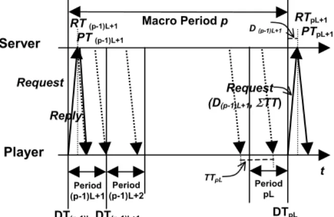
(4) duration between receiving the first and last bit of this period. The client then plays back the data and sends next Request packet to the server at the display time. Case (c): Data bits received before their display time are counted up as the eligible received bits RB ip , but others should be dropped by the client. The transfer time TT pi is measured as the duration between receiving the first bit and the display time DTpi of this period. For minimizing the effect of dropping data, many approaches are possible. The first approach is to use scalable video coding [14] to reduce the data size of next period on the fly. The second one is to dynamically adjust bandwidth among concurrent SMIL objects [14]. The third one is to rearrange the transmission sequence for MPEG-encoded video with I and P frames first [9]. The proposed prefetching algorithms for the server and the client are listed below: The server algorithm: Begin Accept the connection from the client for continuous object i if the access control is granted; Initialize current period p as 1; While (not end of object i) Wait for the Request packet from the client; If (p=1) // the first Request packet PT1i = RT1i ; Else Calculate the prefetching time of period p; PT pi = PT pi −1 + 2 D ip −1 + TT pi −1 ; If ( PT pi < RT pi ) then. PT pi = RT pi ; Endif Send the Reply packet back to the client; Transmit total data bits of period p to the client with rate R ip ; Advance to next period, p = p+1; End; // of while Terminate the connection with the client; End The client algorithm: Begin Setup a connection with the server for continuous object i; Initialize current period p as 1; While (not end of object i) If (p=1) // the first Request packet Send the Request packet to the server; Else Send D ip −1 and TT pi −1 within the Request packet to the server; Endif Wait for the Reply packet from the server;. Calculate D ip of current period; Store data bits arrived before DTpi in the buffer and drop following bits; Calculate RB ip , TT pi and corresponding BW pi ; Display the media data of period p; p = p+1; End; //of while Terminate the connection with the server; End.. 3.4. Scenario for reducing the Request packet For reducing the number of the Request packet, the client sends it to the server every L periods, which is called as the macro period in this paper, instead of every period. Whenever the server receives the Request packet, it will calculate the prefetching time for this macro period and send back the Reply packet as described in the server algorithm. A few modifications are as follow. The server continues transmitting total data bits of this macro period to the client. The client then calculates the total transfer time during this macro period and sends it back to the server with the delay. Equation 4 is modified as Equation 8 to calculate the prefetching time of macro period p. However, the client still has to monitor every period and drop data bits received after its display time, as described in the client algorithm. With this approach, the number of the Request packet is reduced to one L-th of the original requests. However, the calculated prefetching time would be more inaccurate if the delay, ATM ABR bandwidth and encoded video bit rate fluctuate more severely during this macro period. In this way, consumed buffers in the client may not be minimized. We will examine the tradeoff of this approach in the following simulations. RT (p-1)L+1 PT (p-1)L+1. Server. Macro Period p. Request Reply. D (p-1)L+1. RTpL+1 PTpL+1. Request (D(p-1)L+1, ΣTT). Player Period Period (p-1)L+1 (p-1)L+2. DT(p-1)L DT(p-1)L+1. TTpL. t Period pL. DTpL. Figure 3. Scenario for reducing the Request packet.
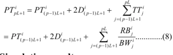
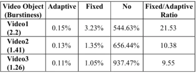
(5) pL. ∑ TT. PT pLi +1 = PT(ip −1) L +1 + 2 D(i p −1) L +1 + = PT(ip −1) L +1 + 2 D(i p −1) L +1 +. j = ( p −1) L +1. i j. RB ij .............(8) i j = ( p −1) L +1 BW j pL. ∑. 4. Simulation results The wireless ATM simulation environment based on the parking lot configuration [16] is shown in Figure 4. Link bandwidth is assumed to be 155Mbps. The last link to the mobile client is a wireless ATM connection. The background VBR connection passes through all three switches from Server 2. The background ABR1 connection comes from Server 3 to Client 1 through all three switches and the background ABR2 connection comes from Server 7 to Client 2 through Switch 3. Three VBR-encoded video clips with different burstiness values are transmitted individually by an inexpensive ABR connection, whose bandwidth is varied due to the background VBR and ABR connections, from Server 1 to mobile Client 3 through all three switches. The cell delay within a switch is linearly proportional to the queue length of each switch. Traffic parameters of all connections are listed in Table 1. Their bit rate diagrams are shown in Figure 5, 6 and 7 respectively and their burstiness values are listed in Table 1. With the GOP sequence of these MPEG-encoded videos as IBBPBBPBBPBBPBB, the display duration is 500ms in our simulations.. SERVER2. SERVER4. ATM SWITCH #1. SERVER6. ATM SWITCH #2. Client#1. ATM SWITCH #3. Client#2. SERVER1. Mobile Host (Client#3) SERVER3. SERVER5. SERVER7. Figure 4. The Wireless ATM simulation environment Table 1. Traffic parameters in the simulation Object Size Peak Min. Avg. Burstiness Name (Mbps) Rate Rate Rate (Peak/Avg.) VBR. 84.8. 6.4. 2.34 4.29. 1.49. ABR1. 8. 0.6. 0.04 0.42. 1.42. ABR2. 8. 0.6. 0.04 0.42. 1.42. 0.9. 0.1. 0.41. 2.2. Video2 14.3 0.52. 0.1. 0.37. 1.41. Video3 11.2 0.34 0.12 0.27. 1.26. Video1 15.7. Source Poisson process (λ=200 cell/ms) Poisson process (λ=18 cell/ms) Poisson process (λ=18 cell/ms) Rush Hour MPEG2 40:14-40:34 sec. Runaway Bride MPEG2 25:50-26:10 sec Runaway Bride MPEG2 37:44-38:04 sec. Simulation results with three prefetching protocols, i.e., no prefetching, fixed prefetching, and our adaptive QoSguaranteed prefetching schemes, are compared. With the no prefetching scheme, the media server uses all available ABR bandwidth to transmit the video data to the mobile client. With the fixed prefetching protocol, the server simply transmits data bits of next period one period, i.e., 500ms, earlier. It then stops and waits for next period. However, video bits of next period in our adaptive scheme can be sent at the most appropriate time which is adjusted with the client’s feedback information. First, Figure 8, 9 and 10 show curves of the total received data with time for three video clips by these three schemes on the client. Because the no prefetching scheme conveys video data with all available bandwidth, the mobile client receives more data such that its curves are far away from those of other two schemes. With our adaptive scheme, the server dynamically transmits the data depending on the measured bandwidth and delay values such that its curves are far close to those of the client actually needs than curves of the fixed scheme are. Second, the extra buffer percentage at each time is defined as the difference between the total received data and the actual needed data divided by the bit rate of the video at that time. As shown in Figure 11, 12 and 13, our adaptive scheme consumes much less percent of extra buffer to store video data not necessary at that time than the fixed scheme, let alone the no prefetching scheme. Table 2 lists the average percentages of extra buffer for these three schemes. Our adaptive scheme significantly reduces the extra buffer consumption to at least one tenth of the fixed scheme. Third, different L values are simulated to reduce the overhead of our adaptive scheme. Their percentages of extra buffer for the three video clips are shown in Figure 14, 15 and 16 respectively. Their average percentage values are illustrated in Table 3. The larger the L value is, the more average percentage the extra buffer consumed. Our adaptive scheme with a specific L value still outperforms over the fixed scheme that prefetches data of next L periods once. Further, these performance metrics are closely related to the burstiness values of the video clips. The larger the burstiness value of the video clip is, the larger the ratio, which is average extra buffer percentages of the fixed scheme over that of the adaptive scheme, is. It means if the VBR-encoded video has larger burstiness value, the adaptive scheme is much better than the fixed scheme (table 2) and the average percentage of extra buffer grows faster with the increasing L value (table3)..
(6) Table 2. Average percentages of extra buffer for video 1, 2 and 3 with three prefetching schemes Video Object Adaptive (Burstiness) Video1 0.15% (2.2) Video2 0.13% (1.41) Video3 0.11% (1.26). Fixed. No. Fixed/Adaptive Ratio. 3.23%. 544.63%. 21.53. 1.35%. 656.44%. 10.38. 1.05%. 937.47%. 9.55. Table 3. Average percentages of extra buffer for video 1, 2 and 3 with different request (L) values by the adaptive scheme Object Video1 (2.2) Video2 (1.41) Video3 (1.26). L=1 0.15% 0.13% 0.11%. L=2 3.2% 3.1% 2.0%. L=4 8.41% 8.04% 4.24%. L=8 26.09% 22.67% 10.70%. 5. Conclusion In this paper, an adaptive QoS-guaranteed prefetching scheme for VBR-encoded continuous objects is proposed to minimize the size of extra buffer used by the resourcelimited client under fluctuated network bandwidth and delay. A scenario to reduce the scheme overhead is also described. Simulation results illustrate excellent performance results of this scheme over other two prefetching schemes, especially for bursty video clips. It achieves at least ten times reduction on average consumed extra buffer.. 6. References [1] W3C, “W3C Issues Synchronized Multimedia Integration Language (SMIL 2.0) Specification”, http://www.w3.org/TR/SMIL20.html, 2000. [2] The SMIL 2.0 Prefetch Control Module, http://www.w3.org/TR/smil20/smil-content.html#edef-prefetch, 2001. [3] Microsoft Internet Explorer 6.0 Public Preview, http://microsoft.com/windows/ie/preview/default.asp, 2001. [4] Real One Platform, http://www.realnetworks.com/solutions/ecosystem/realone.html? src=rnhmfs, 2001.. [5] X-Smiles, http://www.x-smiles.org, 2001. [6] Networkfusion, “Qwest Revealed to Network World Last Week a New Line of Enterprise Services in the Basic Categories Favored by the Big 3 Carriers: Frame Relay, ATM, Private Lines and Internet Access”, http://www.nwfusion.com/news/1214qwest.html, 1998. [7] F. Fluckiger, “Understanding Networked Multimedia: Applications and Technology”, Prentice Hall, 1995. [8] M. Reisslein and K.W. Ross, “High-performance Prefetching Protocols for VBR Prerecorded Video”, IEEE Network, Vol. 12, Nov. 1998, pp. 46 – 55. [9] C. S. Lin, M. Y. Wu and W. Shu, ”Transmitting VariableBit-Rate Videos on clustered VoD systems”, IEEE International Conference on Multimedia and Expo, Vol. 3, 2000, pp. 14611464. [10] R. Sabat and C. Williamson, “Cluster-based Smoothing for MPEG-based Video-on-demand Systems”, IEEE International Conference on Performance, Computing, and Communications, 2001, pp. 339-346. [11] D. Y. Lee and H. Y. Yeom, “Tip Prefetching: Dealing with the Bit Rate Variability of Video Streams”, IEEE International Conference on Multimedia Computing and Systems, Vol. 2, June 1999, pp. 352 – 356. [12] L. Zhang, S. Deering, D. Estrin, S. Shenker and D. Zappala, “RSVP: A New Resource ReSerVation Protocol”, IEEE Network, Sept. 1993. [13] B. Barak, S. Halevi, A. Herzberg and D. Naor, “Clock Synchronization with Faults and Recoveries”, the Nineteenth Annual ACM Symposium on Principles of Distributed Computing, July 2000, pp. 133-142. [14] D. Wu, Y.T. Hou and Y.Q. Zhang, “Scalable Video Coding and Transport over Broad-Band Wireless Networks”, Proceedings of IEEE, Vol. 89, No. 1, Jan. 2001, pp. 6-20. [15] I. C. Chang and S. W. Hsieh, “An Adaptive QoS Guarantee Framework for SMIL Multimedia Presentations with ATM ABR Service”, Master Thesis, Department of Information Management, Chaoyang University of Technology, 2001. [16] C.L. Lee, Y.C. Chen and J.R Chen, “A Simplified Approach Based on Source Control for ATM ABR Service”, Computer Communication, vol. 24, pp.1272-1282, 2001..
(7) 0.9. 0.8. 1. Video2. 0.9 0.8. 0.7. 0.8 0.7. 0.6. 0.6. 0.6. 0.5. 0.5. 0.5. 0.4. 0.4. 0.4. 0.3. 0.3. 0.2. 0.2. 0.3 0.2. time. 0 5000. 10000. 15000. time. 0 0. 20000. MB. Fig. 5 Bit rate diagram of video 1. 16. 0.1 5000. 10000. 15000. Fig. 6 Bit rate diagram of video 2. 16. 0 0. 16. 14. 14. 12. 12. 12. 10. 10. 10. 8. 8. Actual. 8. 6. Adaptive. 6. 6 4 2. time. 0. Fixed. 4. time. 0 0. 5000. 10000. 15000. 20000. 0. 5000. 10000. 15000. 10000. 15000. 20000. Actual Adaptive Fixed No. 4. No. 2. 5000. Fig. 7 Bit rate diagram of video 3.. 14. Actual Adaptive Fixed No. time. 0.1. 20000. MB. 0. 0.7. MB. 0.1. Video3. MB. 1. Video1. MB. MB. 1 0.9. 20000. 2. time. 0 0. 5000. 10000. 15000. 20000. Fixed. 5000. 10000. 15000. 20000 time. 11% 10% 9% 8% 7% 6% 5% 4% 3% 2% 1% 0% -1% -2% 0 -3% -4% -5% -6%. %. Adaptive. %. 11% 10% 9% 8% 7% 6% 5% 4% 3% 2% 1% 0% -1% -2% 0 -3% -4% -5% -6%. Adaptive Fixed. 5000. 10000. 15000. 20000. time. 11% 10% 9% 8% 7% 6% 5% 4% 3% 2% 1% 0% -1% 0 -2% -3% -4% -5% -6%. %. Fig. 8 Total received sizes for video 1 Fig. 9 Total received sizes for video 2 Fig. 10 Total received sizes for video 3 with three prefetching schemes with three prefetching schemes with three prefetching schemes Adaptive Fixed. 5000. 10000. 15000. 20000. time. L1. L1. L2 45%. L4. %. %. %. Fig. 11 Extra buffer percentages for Fig. 12 Extra buffer percentages for Fig. 13 Extra buffer percentages for video 1 with two prefetching schemes video 2 with two prefetching schemes video 3 with two prefetching schemes L2. 45%. L2 45%. L8. L8. 35%. 35%. 25%. 25%. 25%. 15%. 15%. 15%. time. -5%. 0. 5000. 10000. 15000. 20000. Fig. 14 Extra buffer percentages for video 1 with different L values. L4. L4. L8. 5%. L1. 5%. -5%. time 0. 5000. 10000. 15000. 20000. Fig. 15 Extra buffer percentages for video 2 with different L values. 35%. time. 5%. -5%. 0. 5000. 10000. 15000. 20000. Fig. 16 Extra buffer percentages for video 3 with different L values.
(8)
數據

相關文件
Although many excellent resource synchronization protocols have been pro- posed, most of them are either for hard real-time task scheduling with the maxi- mum priority inversion
Propose eQoS, which serves as a gene ral framework for reasoning about th e energy efficiency trade-off in int eractive mobile Web applications. Demonstrate a working prototype and
▪ Approximation algorithms for optimization problems: the approximate solution is guaranteed to be close to the exact solution (i.e., the optimal value)..
• If we want analysis with amortized costs to show that in the worst cast the average cost per operation is small, the total amortized cost of a sequence of operations must be
The Ministry of Justice look highly upon the operation of volunteer, which can be assorted into four categories by its clients, some for the crime victims , some for
In 2006, most School Heads perceived that the NET’s role as primarily to collaborate with the local English teachers, act as an English language resource for students,
Abstract We investigate some properties related to the generalized Newton method for the Fischer-Burmeister (FB) function over second-order cones, which allows us to reformulate
Shih, “On Demand QoS Multicast Routing Protocol for Mobile Ad Hoc Networks”, Special Session on Graph Theory and Applications, The 9th International Conference on Computer Science
