212 IEEE JOURNAL ON SELECTED AREAS IN COMMUNICATIONS, VOL. 14, NO 1, JANUARY 1996
A Multimedia Sync onization
el
Its Implementation in Transport
IS
Chun-Chum Yang and Jau-Hsiung Huang, Associate Member, IEEE
Abstract-An implementation of a synchronization mechanism in transport protocol to support multimedia applications over a packet or cell switched network is proposed. In designing such a mechanism for practical use, ease of implementation and capability of handling random delay of packets are two key issues for success. Since the random delay of packet or cell switched networks makes synchronization among media more complicated after the transmission across the network, a model which considers the random transmission delay is hence required to specify the temporal relationship among media. Therefore, a real-time synchronization model is presented to satisfy this requirement in the paper. Based on the proposed synchronization model, a transport protocol, namely multimedia synchronization transport protocol, is designed and implemented. The perfor- mance measurement of such a protocol is also presented.
I. INTRODUCTION
ITH THE increasing power of modern computers and high-speed network technologies, the integration of
multiple media into a single network application becomes possible; such as video conferencing, shared workspace and groupware systems [ 11-[SI. For multimedia applications, syn- chronization is a very important issue which means the inter- media temporal relationship has to be satisfied across the network. To tackle such a problem, we have to first examine the characteristics of packethell switched network and the characteristics of media.
Two major problems of packet or cell switched network supporting real-time multimedia applications are random delay and lost packets, due in large part to buffer overflow. Hence, the temporal relationship among media may be destroyed at the receiver even if they were sent in synchronization by the sender. Worse yet, since each medium is usually transmitted through a separate connection and the quality of service of connections may be different; the delay characteristics of different media may be different. Thus, a synchronization mechanism should be implemented at the receiver to regain
the synchronization among media.
Much work [9]-[13] has been done in describing the syn- chronization model for multimedia applications. Among those, Petri-net based models provide a good method to specify temporal relationships. ,A modified Petri-net model, object
Manuscript received August 7, 1994; revised April 5, 1995.
The authors are with the Communications and Multimedia Laboratory, Depatment of Computer Science and Information Engineering, National Taiwan University, Taipei, R.O.C., Taiwan (e-mail: jau@csie, nut.edu.tw).
Publisher Item Identifier S 0733-87 16(96)00228-4.
P t4
V : video, Tx : text, A : audio
Fig. 1. An example of Petri net based synchronization model.
composition Petri net (OCPN) model [lo], [ l l ] , has been proved to have the ability to specify any arbitrary temporal relationship among media and it may be applied to both stored-data applications and live applications. The extended OCPN (XOCPN) [12] can additionally specify the commu- nication functions. In [13], user actions are also considered. However, when taking the real-time issue of multimedia and the random delay of packethell networks into consideration,
OCPN/XOCPN and other Petri net based models are not sufficient to deal with the late transmission of packets. Here, we define late transmission of a packet to be that the packet fails to reach its destination in time (i.e., exceeding its real- time constraint) and should be dropped. We explain the insufficiency of OCPN by the example shown in Fig. 1 in the following.
We may treat the example in Fig. 1 as an MTV-like applica- tion in which there is music (audio) and corresponding video frames and text (subtitle) on the screen. In Fig. 1, we only show two cycles of a cyclic model of the application and the interpretation of transition tl to t 3 follows. Simultaneously, the application plays audio A I , displays two video frames V I , V,
orderly, and displays text T x l . Fig. 1 shows that transition t 3 will be fired only after V2, A1 and Txl finish playing. Similarly, transition t 5 will be fired only after Vq, A2, and Txa finish playing.
In the following, we examine the characteristics of audio, video, and text data. For audio data, it is very jitter sensitive and cannot tolerate random delay between audio segments; hence, by holding A2 too long after finishing AI will result in unrecognizable audio quality. For video frames, by dropping a small portion of video frames or by having a small random delay between video frames may only have a minor impact on human eyes and may be acceptable. For text data, it has the least jitter sensitivity compared to audio and video. Based on such an observation, we notice that audio data is much more jitter sensitive than video and text data.
YANG AND HUANG A MULTIMEDIA SYNCHRONIZATION MODEL AND ITS IMPLEMENTATION IN TRANSPORT PROTOCOLS 213
In Fig. 1 based on OCPN model, if A1 and T x l have
finished playing but Vz is late due to network congestion, transition t 3 can not be fired until Vz arrives and finishes playing. For this late transmission of V2, A2 car1 not be played
even if its data has arrived. However, this is improper since audio is very jitter sensitive as explained earlier. Therefore, a natural thought in handling this situation is to fire transition
t 3 right after finishing A1 to activate A2 in order to maintain
the audio quality. Clearly, the unfinished video frames in Vz
will be dropped.
However, any of the earlier proposed Pelri net models does not allow firing transition t 3 before finishing V,. More precisely, they only describe the synchronization relationship under perfect network condition or require a known network delay bound for video-on-demand type of applications. In wide area packetkell networks, it is impractical to make such an assumption since the upper bound of network delay is too large to support live applications such as video conference. Hence, a new model will be proposed in this paper and is named as Real-Time Synchronization Model (6:TSM). As will be explained in Section 11, the definition and firing rules of RTSM are different from the Petri-net based models.
There is another question raised after defining the RTSM model. That is, where do we place the synchrclnization mech- anism in the network architecture? We have two1 choices for the answer: 1) in the application, or 2) in the transport protocol. To place the synchronization mechanism in the application means that the application has to handle all the synchroniza- tion control for itself, which will introduce more overhead to the application. However, more complex synchronization relationships can be supported if the synchronization mecha- nism is implemented in the application. Multimedia titles and documents with complex synchronization relationships and no repeated cycles (as in Fig. 1) may be applications of this category.
On the other hand, we can place the synchroinization mecha- nism in the transport protocol. A transport protocol supporting synchronization mechanism is trying to simulate an end-to- end connection as a circuit, where the receiving application receives data with the same temporal relationship as they were sent by the sender. Hence, the application at the receiver simply has to receive and play data since the synchronization is provided by the transport protocol. Thus, the design of applications is simplified. Applications such as video con- ference where a simpler synchronization relationship with repeated cycles may belong to this category. In this paper, we apply the proposed RTSM model in tlhe design of a new transport protocol, namely Multimedia Synchronization Transport Protocol (MSTP) for synchronization purpose.
As to the part of the transport protocols, much work [ 141-[24] has been done in discussing high-speed transport protocols. The goals of these protocols are fixused on high- throughput or low-latency. The issue of real-time synchroniza- tion in multimedia applications is rarely addressed [25]-[29]. In [25], Huitema and Dabbous discussed the synchronization relationship between different types of data. However, that model did not address the real-time characteristics of media, and it could not achieve more complex sync'hronization rela-
tionship since it had only two types of data (RT, DT). In this paper, MSTP is presented to support more general services.
The remainder of this paper is organized as follows. In Section 11, the RTSM and the concept of key medium and
time medium are presented. The goal of key medium and time medium is to handle situations when data must be dropped
due to late transmissions. Section I11 describes the architecture, the packet format, and the synchronization control mechanism of MSTP. The implementation and performance evaluation of MSTP are discussed in Section IV. Finally, Section V concludes this paper.
11. REAL-TIME SYNCHRONIZATION MODEL (RTSM)
Before introducing the definition of RTSM, we explain some terminologies used in the model. The elements in RTSM include place, token, and transition, as in the OCPN model
[lo]. The places are used to represent the medium unit (such as audio segments, video frames, or text strings) and their corresponding actions (such as playing audio, displaying video, or text on the screen). There could be one or zero
token within a place to represent the state of the place. A
place without token means the place is currently inactive. A place with a token is active and could be in one of the two states: token is blocked or unblocked. When a token is just added into a place, the corresponding action of the place can be executed, and before finishing the action, the token is blocked. The token in the place is unblocked after the action is finished. Transitions are used to represent the synchronization relationship between places. However, the places in RTSM are divided into two types further, and a new firing rule for RTSM is also proposed for the real-time issue. We explain the new idea in the following.
Considering the example in Fig. 1, in order to avoid the unexpected blocking due to late transmission, we need a mechanism to enforce some blocked transitions to be fired under the situation of late transmissions. In RTSM, there are two kinds of places as regular places and enforced places. To differentiate an enforced place from a regular place, a double circle is drawn for enforced place as shown in Fig. 2 where transition t 3 is fed by two regular places, Vz and Txl, and one enforced place, Al.
The firing rule about enforced places is that once an enforced place gets unblocked, the transition following it will be immediately fired regardless of the states of other places feeding this transition. Therefore, if A1 becomes unblocked
in Fig. 2, transition t 3 will be immediately fired regardless of the states of Vz and T z l . At the same time, tokens in
the places before transition t 3 , such as Vl,V2 or T z l , must
be cleared since these places are obsolete due to the firing of t 3 . We call this action of clearing all obsolete tokens
backtracking, since the action is backtracked from the fired transition in RTSM. In this way, the synchronization anomaly
due to late transmission is solved. The following are the complete definition, firing rules and backtracking rules of RTSM. Notice that with the inclusion of enforced places and enforced firing, this synchronization model is different from Petri net in nature. However, there are still some similarities
214 IEEE JOURNAL ON SELECTED AREAS W COMMUNICATIONS, VOL. 14, NO. 1, JANUARY 1996
n t4
Fig. 2. An RTSM model for the example in Fig. 1.
The stop point
of backtracking A backtracking
saithg transitii \=/ ei
places and transitions.
A. Dejinition of RTSM where Definition 1: RTSM is a seven-tuple ( T , P, E , A ,
D ,
R, M ) , T = { t i , & ,. . .
, t n } P = {pl,
p z, . . .
,
p m } E = {el e 2 , .. .
,
e,} S = P U E All places. A: (2' x S } U ( S T } D:S + Realnumber R: S -+ ( r l ~ r 2 ,.
. .,
.I;} M :s
+ {0,1,2}Each place may be in one of the following states: 0: no token
1: token is blocked Cross in the place.
2: token is unblocked Dot in the place. Transitions.
Regular places (single circles). Enforced places.
Directed arcs.
Time duration of places. Type of media. State of places.
Dejinition 2: To Initiate RTSM is to add a token to the initial Dejnition 3: Firing rules of RTSM
Case (a): Transition t, does not contain any enforced place 1) Transition t, fires immediately when each of its input
places contains an unblocked token.
2) Upon firing, transition t , removes a token from each of its input places and adds a token to each of its output places.
3) After receiving a token, a place p, remains in the active
state for the interval specified by the duration 7,. During
this interval, the token is blocked.
Case (b): Transition t, contains at least one enforced place
1) When the token in any one of the enforced places e, becomes unblocked, transition
t,
is fired regardless of the states of other input places.2) Upon firing, a set of backtracking rules is exercised to remove tokens from their input places. The backtracking rules will be explained in the following. Meanwhile, transition t, adds a token to each of its output places. To maintain the consistency of the progress of RTSM, a backtracking mechanism is required. For instance, considering a run-time case of Fig. 2: tokens in T x j and A1 are unblocked, and the token in VI is blocked, i.e., actions associated with
places Txl and A1 are finished while the action with place
VI is still in process. Since place AI is an enforced place,
transition t3 fires when the token in place A1 becomes unblocked. To fire transition t 3 , we have to remove the tokens in the places before transition t 3 , and add a token into each place.
in its input places.
e, in its input places.
of the output places of transition t 3 : V3, Txz and Az. That is,
we have to remove not only the tokens in places Txl and A I
(place Vz contains no token in this case), but also the token
in place V I . By applying the firing rule case(a)-(2), which
is used in the case of nonenforced firing, to this case is not enough, since it only removes tokens in the input places of the fired transition. Therefore, a backtracking action to remove tokens in the places before transition t 3 is required, and the backtracking action will remove the token in place VI in this
case.
In summary, when an enforced firing occurs, there may exist some places which are in front of the fired transition and contain tokens within them, so we have to remove these obsolete tokens to match the correct state of the model. We may start the clearing action from the initial place of RTSM
until reaching the just fired transition. However, backtracking is a more efficient way since it eliminates unnecessary travers- ing. As shown in Fig. 2, transition t3 will be immediately fired
as long as A1 finishes playing regardless of the states of Txl
or V,. However, by firing t3, if there are tokens in T x l l VI or Vz, these tokens should be removed since their contents are
skipped. In the following, we will describe the backtracking rules to remove tokens under such situations. The backtracking rules will first remove the token from the unblocked enforced place, then the following three rules should be exercised.
Backtracking rules of RTSM:
Rule 1: The action of backtracking stops at the starting transition t , of the enforced place e, or at the initial
place as shown in Fig. 3.
Rule 2: During backtracking, if a place containing a token (either blocked or unblocked) is backtracked, then remove the token and stop the backtracking of this
branch.
Rule 3: During backtracking, if a transition is reached with nonbacktracked output places, fire this transition to
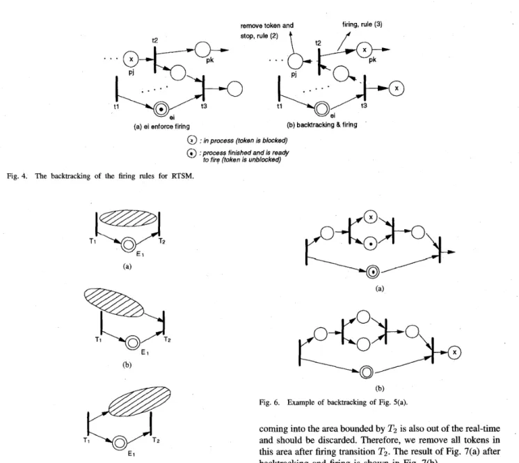
activate the nonbacktracked output places. We use Fig. 4 as an example to explain the backtracking rules. As shown in Fig. 4(a), enforced place e, becomes unblocked and will fire transition t3 with place p , being active. Applying rule (2) of the backtracking, the token in
p , will be removed as shown Fig.*4(b). Similarly, transition t z will be fired and a token will be added in p k since it is a nonbacktracked output place as explained in rule (3).
In the following, we examine the effect of enforced places and the backtracking rules by looking at all possible cases. For an enforced place, we show that the relation between this enforced place and the rest of the RTSM must be in one of the
YANG AND HUANG A MULTIMEDIA SYNCHRONIZATION hlODEL AND ITS IMPLEMENTATION IN TRANSPORT PROTOCOLS
remove token and firing, rule (3) rule (2)
. . .
(a) si enforce firing (b) bacMracking &firing
G)
: in process (token is blocked)a) :process finished and is ready to fire (token is unblocked) Fig. 4. The backtracking of the firing rules for RTSM.
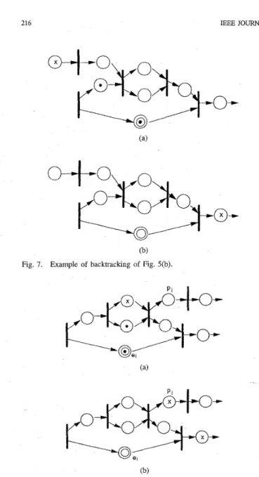
Fig. 5. Three relations between enforced places and the RTSM.
three cases as shown in Fig. 5. Fig. 5(a) shows that the places affected by the enforced place El is bounded by transitions TI and T2, which are the starting and ending transitions of E1
respectively. An example of this case is shown in Fig. 6(a). In this case, it means that all transitions and places affected by the enforced place are within the area bounded by TI and T2.
Thus, the firing of Tz due to the enforced place El means that the unfinished work within the area bounded by TI and T2
is late and has exceeded the real-time constraint. Hence, we have to exercise the backtracking rules to remove all tokens in this area after firing transition T2. Fig. 6(b) shows the result
of Fig. 6(a) after backtracking and firing.
Case (b) of Fig. 5 shows that the places affected by El reach
beyond TI and an example of this case is shown in Fig. 7(a). This case is similar to case 5(a) where El enfisrces a firing in
transition T2 means that all unfinished work in the branches
n
n
(b) Fig. 6. Example of backtracking of Fig. 5(a).
215
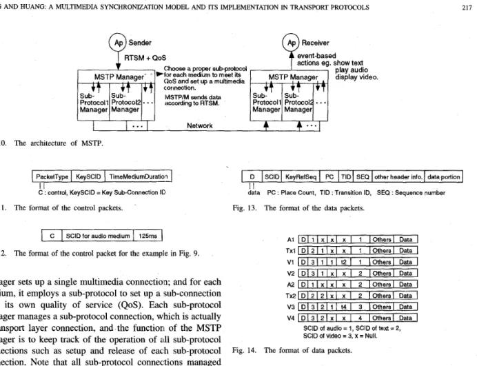
coming into the area bounded by T2 is also out of the real-time
and should be discarded. Therefore, we remove all tokens in this area after firing transition T2. The result of Fig. 7(a) after
backtracking and firing is shown in Fig. 7(b).
Lastly, case (c) of Fig. 5 shows that the affected places by
El reach beyond T2. In this case, not all places and transitions in the shaded area are fully controlled by the enforced place E l . An example of this case is shown in Fig. 8(a) where place
p , is not controlled by enforced place e, for synchronization. Hence, the enforced firing of transition Tz does not mean that
we should remove all tokens in the shaded area. The solution to this situation is described in Rule (3) of the backtracking rules. That is, during backtracking, when meeting a transition
T, with output places which are not bounded in the range of
backtracking, we enforce this kind of transitions to be fired. The result of Fig. 8(a) after backtracking and firing is shown in Fig. 8(b).
B. Concept of Key Medium and Time Medium
I ) Key Medium: In this section, we will discuss how to assign enforced places to packets of different media. By definition, enforced places control the advance of time of
216 IEEE JOURNAL ON SELECTED AREAS IN COMMUNICATIONS, VOL 14, NO 1, JANUARY 1996
(b)
Fig. 7. Example of backtracking of Fig. 5(b).
(b)
Fig. 8. Example of backtracking of Fig. 5(c)
medium, such as voice, are assigned as enforced places, then this medium will not be blocked due to late transmissions of
other media for synchronization. Further, this medium will drive other media to advance in time if late transmissions happen to them. We denote this specific medium as the key medium. The concept of key medium is similar to that of
masterhlave policy proposed in [26], but is more compact
for network applications.
Therefore, two factors should be considered in deciding the key medium. First is the importance of the medium and second is the jitter-sensitivity of the medium. For instance, if the quality of one medium is more important than that of others, then this medium should be chosen as the key medium. Or, if the importance of all media is the same, then the most jitter sensitive medium should be chosen as the key.
Note that all media except the key medium are subject to packet dropping due to late transmissions. Hence, if there is one medium requiring error free transmission, such as numerical data, then this medium should be either chosen as
t2 t4
-
T : time medium. Fig. 9. Using time medium in RTSM model.
the key medium or should not be controlled by another key medium. Fig. 2 shows an example where text data and video
data can be dropped due to late transmissions when audio data gets unblocked. Hence, in t h s case, error free transmission is not guaranteed to text and video transfer.
2) Erne Medium: Since all media are transmitted across the network, it is also possible for the key medium to suffer a long delay such that its real-time constraint is exceeded. Therefore, what should be done if A I in Fig. 2 is still waiting for its packets due to late transmissions while its real-time constraint has expired?
In
such a case, it is reasonable to fire transition t 3 to activate A2, V3 and Tx2 instead of waiting forA I in order to maintain the quality of audio. To achieve this function, the introduction of key medium is not sufficient and we need a mechanism to express absolute time (the real-time constraint) in the model. For this goal, we introduce time as one of the media, named time medium, and can be placed in the synchronization model of multimedia applications.
Clearly, time medium is a virtual medium and normally contains a deterministic duration of time which specifies the real-time constraint between two transitions. Note that time medium can be assigned as regular places or enforced places. By assigning the places of time medium to be enforced places means that the transition following the enforced place of the time medium will be fired when the duration of time specified by the time medium expires, even if the places of other media are stiU blocked.
With the introduction of time medium, we can model the example of Fig. 2 to be that shown in Fig. 9. Note that in Fig. 9, both places of audio and time are assigned as enforced places. Fig. 9 shows that transition t 3 will be fired if either one of the following two cases is true. One is that A1 has finished playing and becomes unblocked; or, 125 ms has passed by after the firing of transition tl. Hence, if A1 is blocked for a long time due to late transmission, then A1 will be skipped
when time medium TI becomes unblocked. This resolves the
problem of late transmissions of key medium,
III. MULTIMEDIA SYNCHRONIZATION
TRANSPORT PROTOCOL (MSTP)
ment RTSM in the proposed MSTP protocol in this section.
A. The Architecture of MSTP
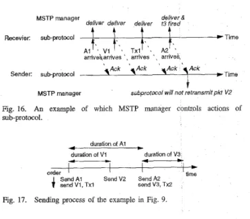
MSTP adopts a multi-protocol architecture [31] as shown in Fig. 10. For an application with multiple media, the MSTP After the introduction of RTSM, we explain how to imple-
YANG AND HUANG: A MULTIMEDIA SYNCHRONIZATION MODEL AND ITS IMPLEMENTATION IN TRANSPORT PROTOCOLS
D
217
SClD KeyRefSeq PC TID SEQ other header info. data portion
Ap Sender
0
C
1
RTSM+QoSSClD for audio medium 125rns
A
MSTP Manager-
Choose a proper sub-protocol (20s and set up a multimedia connection.
IMSTP/M sends data according to RTSM. )fix each medium to meet its
I I
...
NetworkI I
...
Fig. 10. The architecture of MSTP.
1
PacketTypeI
KeysCIDI
TimeMediumDuratioid C I I : control, KeySClD = Key Sub-Connection IC1 Fig. 11. The format of the control packets. ~manager sets up a single multimedia connection; and for each medium, it employs a sub-protocol to set up a sub-connection with its own quality of service (QoS). Each sub-protocol
manager manages a sub-protocol connection, which is actually a transport layer connection, and the function of the MSTP manager is to keep track of the operation of all sub-protocol connections such as setup and release of each sub-protocol connection. Note that all sub-protocol connections managed by a single MSTP manager belong to a single multimedia application. The purpose of MSTP is to provide a synchronized data stream from sender to receiver. That is, the sender sends data according to a synchronization relationship and MSTP will deliver data to the application at the receiver conforming to the original synchronization relationship.
Briefly speaking, the MSTP manager at the isender (sending MSTP manager) accepts RTSM and QoS for each medium
from the application program, and sets up a multimedia connection with the MSTP manager at the rewiver (receiving MSTP manager). After the connection is seit up, the send- ing MSTP manager will send packets according to RTSM, and the receiving MSTP manager will deid with out-of- synchronization situations and deliver proper packets to the receiver application. In this way, applications at both sides do not need to deal with the control for synchrordzation because MSTP manager will handle it. This simplifies the design of
applications programs.
B. Packet Format of MSTP
There are two kinds of packets sent by the IMSTP manager: control packets and data packets. Control packets are used to send control information to set up, release and change configuration of connections. The synchronization related con- figurations are: 1) which sub-connection is the key medium sub-connection (denoted by KeySCID), and 2) the duration of the time medium (denoted by TimeMediumlhration) which is accompanied with the key medium. The sending MSTP
V 2 1 D 1 3 l l l x l x I 2 IOthersI Data
I
A 2 1 D l l l x l x l x I 2 IOthersI Data
I
T ~ 2 I D 1 2 1 2 1 x ) x I 2 (Others1 DataV3
I
D I 3 1 2 1 1 I 14 I 3 I Others1 Data V 4 1 D 1 3 1 2 ( x 1 x I 4 IOthersI DataSClD of audio = 1, SCID of text = 2,
SClD of video = 3, x = Null.
Fig. 14. The format of data packets.
manager sends control packets to inform the receiving MSTP manager about current configuration of the connection. Fig. 11 shows the format of control packets. Note that the format only addresses the issues of synchronization and does not show other header information such as port numbers, QoS, etc. The
control packet for the example in Fig. 9 is shown in Fig. 12 which has to be sent to the receiving MSTP manager before the connection is set up.
The packet format of data packets is shown in Fig. 13. The field SCID (subconnection identifier) is used to indicate which sub-connection this packet belongs to. The KeyRefSeq field indicates the sequence number of the key medium packet with which this data packet has to be synchronized. Notice that the KeyRefSeq fields of key medium packets is null. Fields PC and TID are used for packets of places which do not feed into the same transition with the key medium, such as VI and Vs in Fig. 9. Field PC indicates the total number of places that feed into the transition specified in the field TID.
For example, in Fig. 9, the packet containing VI will have PC = 1 and TID = 2, which means transition t 2 is fed by only one medium. Hence, transition X will be fired when PC number of packets with TID = X have arrived. Field
SEQ indicates the sequence number of this packet in this sub-
connection. Other header information includes port numbers,
QoS, etc. The data portion field contains the real data of the
packet.
We again use the example in Fig. 9 for illustration. The data packets for the example are shown in Fig. 14. Note that fields
218 IEEE JOURNAL ON SELECTED AREAS IN COMMUNICATIONS, VOL. 14, NO 1, JANUARY 1996
A key medium packet arnvBS or time medium timeout
key medium packets m e , or time medium
non key medium normal
packets arrwes
4
finng state
A packet with the KeySeqRef field equals to the sequence of the active key medium packet amyes
Fig 15 State transifion diagram for the sub-protocols with error control.
PC and TID for
T x l ,
Tx2, V2, andV4
are null since they feed into the same transitions with the key medium.C. Interactions Between MSTP Manager and Sub-Protocol Managers
In the following, we will explain how the receiving MSTP manager decide when to fire a transition which is fed by at least one key medium packet (an enforced place). Normdly, this transition will be fired after the key medium packet has finished playing. However, this requires the receiving MSTP
manager to estimate the time to finish playing of the packet and thus introduces more computing overhead and also needs a timer for triggering the event. In order to avoid the overhead, we adopt a looser policy. That is, the receiving MSTP manager will fire the transition right after the arrival of next key medium packet. For example, transition t 3 in Fig. 9 is enforced to be fired after A2 arrives, which means if any of V I , Vz or T x l has not yet arrived when A2 arrives, it is considered to be
out-of-synchronization and will be dropped. We will explain in detail the operations of the MSTP manager in Section m-D. We classify sub-protocols into two categories, with error control and without error control. Sub-protocols which use acknowledgments and retransmission mechanisms for lost packets, if real-time constraints are not violated, belong to protocols with error control. Sub-protocols without error con- trol will not retransmit lost packets. Actions of sub-protocol managers, such as send, receive, and discard packets, are under control of the MSTP manager.
For a sub-protocol manager with error control, it accepts sendrequests from the MSTP manager and sends packets with proper header information to the corresponding sub- protocol manager at the receiver. Notice that the receiving MSTP manager does not know the RTSM at the sender, so there is no way to inform sub-protocols at the receiver about the sequence number of the next packet to receive once a transition is enforced to fire. For example, if the application RTSM is as shown in Fig. 9, once transition t 3 is enforced to
fire, the video sub-protocol at the receiver could not decide the sequence number of next packet to receive since it does not know how many video places (packets) are accompanied with
A1 by not knowing the source RTSM. What we only know in
such a situation is the sequence number of the currently active key medium packet, i.e., A2 in the example.
Therefore, we define two states for non key medium sub- protocols with error control: 1) normal state, and 2) enforced $ring state. Initially, the sub-protocol is in the normal state, and it must deliver the arriving packet in sequence. In the
MSTP manager deliver &
deliver deliver delwer t3 fired
Recevrer: sub-protocol
t
t
*TimeA,!..
arnveSarnves v1
t'..
' ~ TXlt'.. arrives A 2 . . arrive;.3 A c k \A& \Ack q A c k
Sender: sub-protocol ).Time
I
MSTP manager subprotocol will not retransmit pkt VZ Fig. 16. An example of which MSTP manager controls actions of sub-protocol. duration of A1 duration of V3 duration of V I
-
-
I I I l b order4
SeAd A I SdndV2 ShndA2 Ithesend VI, Txl send V3, Tx2
Fig. 17. Sending process of the example in Fig. 9.
normal state, the sub-protocol is aware of the sequence number
of the next packet to receive, and thus it could perform the operations of error control. However, in the enforced firing state, which means a transition was just enforced to fire, the sub-protocol only knows the sequence number of the currently active key medium packet as explained in the last paragraph. Thus it works as a protocol without error control, and accepts the arriving packet as long as the KeyRefSeq field of the packet is equal to the sequence number of currently active key medium packet. The transitions between the normal state
and enforced firing state are illustrated in Fig. 15.
The MSTP manager could also prevent sub-protocols from retransmitting the out-of-synchronization packets. We illustrate
this by an example as shown in Fig. 16. In this example, although the sender does not receive the ACK of V2, it will not
retransmit V2 since the ACK of A2 has arrived and which will
invalidate Vz because the sender knows the synchronization relationship between them. This retransmission mechanism will obtain a better performance than that of the Slack-ARQ in [30]. The selection of sub-protocols depends on the QoS of each medium.
In
MSTP, the selected sub-protocol for the key medium receives the best service than those of other media.D. Synchronization Control in MSTP
In this sub-section, we explain how MSTP works to support the synchronization services. Recall that the receiving MSTP manager does not know the original RTSM, but deals with
synchronization control according to the information contained in packet headers. Actions taken by the MSTP manager at the sender and receiver will be presented.
I ) Actions of the MSTP Manager at the Sender: After the multimedia connection is set up, the sending process of the
sending MSTP manager is simple. As mentioned in Section
EI-A, it sends packets according to RTSM specified by the
application program. It traverses the RTSM and sends packets
of the place being visited [l 11 by making a send request to
the corresponding sub-protocol of the packet. The sending process of the example in Fig. 9 can be easily realized as shown in Fig. 17.
YANG AND HUANG A MULTIMEDIA SYNCHRONIZATION MODEL AND ITS IMPLEMENTATION IN TRANSPORT PROTOCOLS
SClD KeyRef SEQ (PC, TID) CorrentKeySeq NXT-3 Action Comments
I Null 1 Null I 1 1, 1 accept
2 1 1 (l,t2)
;
1 2, 1 accept1 Null 2 Null
;
2 Null, Null accept (A)3 2 2 Null
:
2 Null, 3 accept (6)219
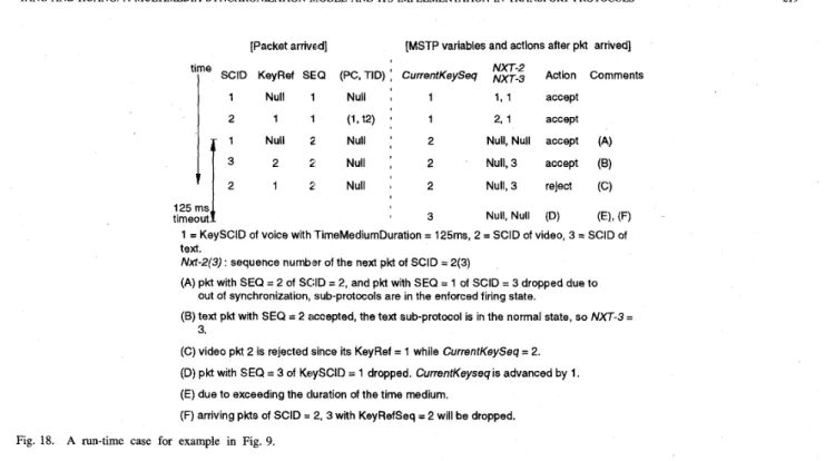
Fig. 18. A run-time case for example in Fig. 9.
2 ) Actions of the MSTP Manager at the Receiver: After the multimedia connection is set up, The receivipg MSTP manager knows the current configuration of the multimedia connection, i.e., KeySCID and TimeMediumDuration, according to the control packet sent by the sending MSTP. The receiving MSTP manager maintains a set of status variables for each connection for synchronization purpose. These variables include:
1) two variables to save current configuraition: KeySCID and TimeMediumDuration,
2) CurrentKeySeq to indicate the sequence number of the currently active key medium packet,
3 j a set of variables to keep the sequence number of next- to-receive packet for each sub-protocol, Nxt-SCID. 4) pairs of variables (APC, TID) to store the number of
packets which feed into transition TID in RTSM. TID is the ID of the transition, and APC is the number of arrived packets whose TID field = TID.
Besides, a timer is needed for the use of time medium.
When the receiving MSTP manager receives one packet from the sub-protocol, it will execute proper actions according to the synchronization algorithm which is briefly explained as following. Any nonkey medium packet with KeyRefSeq =
CurrentKeySeq meets the synchronization relationship with the key medium and can be accepted. The (APC, TZD) pairs are used to synchronize the places which feed into the same transition TZD. The value of APC is increased by one every time a packet with TID field = TID arrives, and the transition is fired when the APC value is equal to the PC field of the arriving packet. That is, all the packets that feed into the transition are ready and should be delivered to the application program.
If the time medium is used, a timeout evenit means that the next key medium packet is too late to be accepted, so that we
advance CurrentKeySeq by one and switch the state of sub- protocols to the enforced firing state as explained in Section
111-C. For applications without use of key medium, RTSM
model can be easily implemented in MSTP protocol by using fields PC and TID in the packet format.
3 ) An Example: We use a run-time case of Fig. 9 to ex- plain the algorithm mentioned above. An arriving pattern and corresponding actions are shown in Fig. 18. In this example, late transmissions of both key-medium and nonkey media are considered. The comments of actions taken are provided in the figure.
IV. IMPLEMENTATION AND ~ R F O R M A N C E MEASUREMENT
We have implemented a prototype system using MSTP pro- tocol and built a simulation system for the wide area network (WAN) environment in order to evaluate the performance of the MSTP protocol. In this section, we describe the system architecture for the simulation and present the results of the performance measurement of RTSM compared with other models. We also discuss the impact of the intra- and inter-
frame video coding schemes on the implementation of RTSM
and MSTP at the end of this section.
A. The Application RTSM and the Implemented Sub-Protocols For simplicity, the application we built is a video phone system which contains audio and video data. The monitor
display is shown in Fig. 19. The audio data is encoded by
the PCM encoding scheme, and the resolution of the video frame is 180 x 140 (QCIF format). The RTSM for the application is shown in Fig. 20. Note that the number of video places corresponding to one audio place is random due to the following reason. At the sender, the application gets
220
sub-connecbon ID m d u m type
1 AucEa
2 m
IEEE JOURNAL ON SELECTED AREAS IN COMMUNICATIONS, VOL. 14, NO. 1, JANUARY 1996
auabiy Of senncas
mw standard chatmn of delay loss prob
100 rns 20 ms 0
120 ms 100 ms 0 01’
Fig. 19. The display of the application on the monitor.
The number of video places israndom
,
,
Fig. 20. The RTSM for the implemented application.
one audio packet from the audio device every 125 ms (i.e., 1 Kbytes audio data), and during this 125 ms, the application gets from the video frame grabber one or two video frames, which is determined by the run-time processing overhead of the operating system. The RTSM of the application is not static but dynamic since the number of video frames corresponding to one audio packet is nondeterministic due to the nonrealtime nature of UNIX. Therefore, the application must inform the sending MSTP manager at the running time about the synchronization relationship between media packets, which is achieved by a procedure call to the MSTP manager. The MSTP manager then fills in proper values in the fields of outgoing MSTP packets, and send them to the receiver via the sub-protocols.
We implemented two kinds of sub-protocols in the system: with and without error control. In the sub-protocol with error control, the arriving packets are accepted if they arrive in
sequence. That is, no gaps in arriving packets are allowed. Hence, the acknowledgments and retransmissions of lost pack- ets are necessary. Nonetheless, if this sub-protocol is used in MSTP, gaps between packets are still possible when enforced
sending host
r - 7
S
f
Ethernetreceiving host
S : sending process, G : gateway process
R : receiving process
Fig. 21. The WAN simulated environment.
firing occurs. In the sub-protocol without error control, a packet is accepted as long as its sequence number is greater than that of any previdusly received packet. Caps are thus allowed in the sub-protocols.
We also define the QoS which are provided by the un- derlying network environment in the simulation system. The parameters of the QoS include the distribution of the delay behavior of packets and the packet loss probability. In the implementation, we built a simulation environment for the
WAN that provides the requested QoS.
B. The WAN Simulated Environment
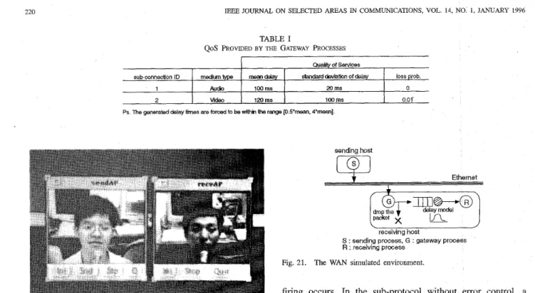
En order to simulate the behavior of a WAN on an Ethernet, we add a gateway process at each destination host to perform proper operations on every packet it receives, which will result in a similar behavior as if the packet is transmitted across a WAN. We illustrate this configuration in Fig. 21.
A gateway process implements a normally distributed delay model and a packet loss probability for each packet. That is, a packet received by the gateway process will be dropped with a probability, or be delayed for some time before forwarding the packet to the receiving process. The delayed time is generated by the delay model.
Since the application we built contains two media, two sub- connections are hence required. Therefore, we implemented two gateway processes, one for each sub-connection. The QoS
provided by each gateway process are listed in Table I. Notice that the delay value generated by the normal distribution is forced to be within the range [0.5*mean, 4*mean] in the program to make the delay values more realistic. As shown in Table I, we provide the audio sub-connection a better QoS since audio is the key medium of the application. The video packets may be dropped by the gateway process with probability 0.01, so that if the selected video sub-protocol requires error control, retransmission of dropped packets may be necessary, depending on whether MSTP is used.
YANG AND HUANG A MULTIMEDIA SYNCHRONIZATION h4ODEL AND ITS IMPLEMENTATION IN TRANSPORT PROTOCOLS 221
Sub-protocol without error control, No Synchronization Control, Audio jit(!ers
250
c
200 2 150 gl 100 3 5 0 e-
.-
'L 100 150 200 250 300 350 packet sequence numberFig. 22. The playing jitters for audio without synchroniz(ztion control, and transmitted by a sub-protocol without error control.
Sub-protocol without error control,
No Synchronization Control, Video jitters
400 r . . . . . . . .
. . .
. .
:.. :;*.: :;.#...
. . .
i:....'.-!
. e.:. ::*.a .: ... * ..< . . *. . .
...
~ ~ ~ - - ~ - ~ ~ ~ ~ " ~ - - ~ ~ - ~ : ~ ~ - ~ - ~ . : - ~ . t . - . ~....
.. .... -.*.,......
.-.
....
:..:____
<:. . . . 1 . *:.: . * * a " - * ..
. . .
.
.
350 . . .. . .
. . .. . .
. . ....
2 250 , .. , * .. . .
.y
300 . . g 200 .: :-.
.
Y. . .
. . . "e-.:-.
..
.:..'-
e..;-.
...
..
.
.-
. . ....
.
...
. . .
...
. . .
...
. . .
. . .
I . . . .. .
:* t:...'. . . I . . ..
.
. . .
.
.
-50d
1,O 2 0 0 '300- 400 500 6;O ;7packet sequence number (frame rate = 12)
Fig. 23. The playing jitters for video without synchronization control, and transmitted by a sub-protocol without error control.
C. Pe~ormance Measurement
The criterion to evaluate the performance of a synchroniza- tion control mechanism is the jitter between the actual playing time and the proper playing time for each paclket. In order to measure the jitter, we have to record the actual1 playing time, and to estimate the proper playing time for each packet. The proper playing time for a packet is estimated by its sending time.
Because the video packet may be dropped lby the gateway process with probability 0.01, the choice of the sub-protocol for video data will affect the performance of the system. In the following subsections A and B , we show the performance measurement of the system without considering the time medium. Sub-protocols without and with error control are discussed in these subsections, respectively. The performance effect of the time medium is presented in subsection C.
1) Sub-Protocols Without Error Control: The results of performance measuring are divided into three parts for comparisons: 1) without any synchronization control, 2) synchronization control by a Petri-net model such as OCPN, and 3) synchronization control by the RTSM with key medium. Video packets dropped by the gateway process are considered
as lost and never retransmitted by the sender since the sub- protocol adopted is without error control. The packets of audio data are never dropped by the gateway process since its packet lost probability is 0 as listed in Table I.
No synchronization control: No synchronization control means that there is no synchronization operation at the re-
Sub-protocol without error control,
Synchronization Control by Petri-net, Audio jitters.
300
r
-
-. : .. . . .
. . .
'. .
. .
. . . .
. . . .
. . .
. . . .
. . .
..
. .
.
.
*.*'... .
.
. .
. . . .
. . .
100 150 200 250 300 350 packet sequence numberFig. 24. The playing jitters for audio with synchronization control by Petri-net, and transmitted by a sub-protocol without ermr control.
Subprotocol without error control,
Synchronization Control by Petri-net, Video jitters
400 350
[.
a . f . . t- . .. . . .
. . . . . ....
. . .
.*.. .
. .
....
...
* 8. i . . ...
,..
-..-.
-50 O h " 100 200 3,O a ;4 . 500 6;packet sequence number (frame rate = 12)
Fig. 25. The playing jitters for video with synchronization control by Petri-net, and transmitted by a sub-protocol without error control.
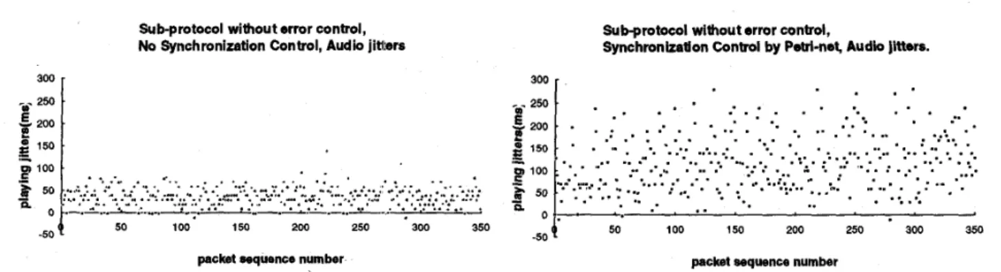
ceiver, but the sender still has to send packets according to the synchronization model. The receiver just plays the packets delivered by the sub-protocols. The jitters of the playing times in this case are shown in Figs. 22 and 23, one for each medium. The frame rate measured equals to 12
frames per second (fps). In the application, we implemented a smoothing buffer of 125 ms in the application at the receiver to smooth out the unavoidable delay jitter. This 125 ms delay introduced by the smoothing buffer is acceptable for video phone application. Hence, the jitters of most audio packets are within the acceptable range (smaller than 125 ms) as shown in Fig. 22. But as we can see in Fig. 23, the jitters of more than 50% of video packets are above 125 ms and many of those are above 300 ms; hence a serious out-of-synchronization phenomenon will be observed.
Synchronization control using the Petri-net model: In this case, the synchronization control of OCPN model is applied at the receiver in order to synchronize the packets. The jitters of audio and video packets are shown in Figs. 24 and 25. Since the audio packets usually arrive earlier than their corresponding video packets, the playing of audio packets is
normally delayed for synchronization purpose. Fig. 25 shows that the audio packets may be seriously delayed such that
the jitters of many audio packets are much greater than 1.25 ms. The quality of audio is hence destroyed and becomes unrecognizable.
Key medium control by the RTSM: We apply the syn-
222 3000 -m- 2500 E 2 2000.
=
1OOo. Y L o o .=
-
P
- 5 0 0 - 0 'IEEE JOURNAL ON SELECTED AREAS IN COMMUNICATIONS, VOL. 14, NO I, JANUARY 1996
r
. . a . .
'
...
...
.
...
Sub-protocol without error control, Key medium Control by RTSM, Audb jittefs.
300
I
-m- 250
.$
1505
200.-
packet sequence number Fig. 26.
transmitted by a sub-protocol without error control.
The playing jitters for audio with key medium control by RTSM, and
Sub-protocol without error control, Key medium Control by RTSM, Video jitters. 400 ~ 350
2
300 . 250 .- -
Y2
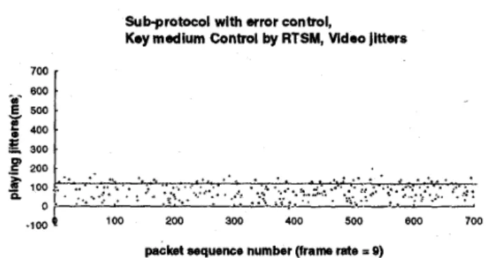
200 .Sub-protocol with error control,
Na Synchronization Control, Audio jitters
100 150 200 250 300 350
packet sequence number Fig. 28.
bransmitted by a sub-protocol with error control.
The playmg jitters for audio without synchronization control, and
Sub-protocol with error control,
No Synchronization Control, Video jitters
. . .
-
-50 i 50 100 150 200 250 3b0 350 400 450 500 550 600
packet sequence number (frame rate = 8)
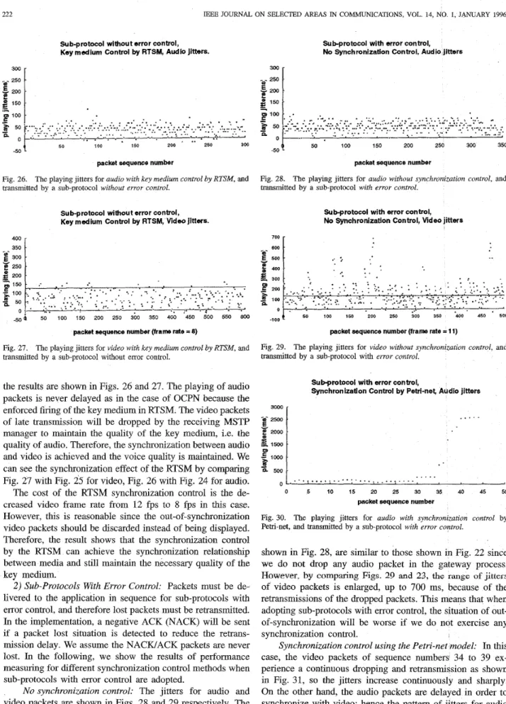
Fig. 27. The playing jitters for video with key medium control by RTSM, and transmitted by a sub-protocol without error control.
the results are shown in Figs. 26 and 27. The playing of audio packets is never delayed as in the case of OCPN because the enforced firing of the key medium in RTSM. The video packets of late transmission will be dropped by the receiving MSW
manager to maintain the quality of the key medium, i.e. the quality of audio. Therefore, the synchronization between audio and video is achieved and the voice quality is maintained. We can see the synchronization effect of the RTSM by comparing Fig. 27 with Fig. 25 for video, Fig. 26 with Fig. 24 for audio. The cost of the RTSM synchronization control is the de- creased video frame rate from 12 fps to 8 fps in this case. However, this is reasonable since the out-of-synchronization video packets should be discarded instead of being displayed. Therefore, the result shows that the synchronization control by the RTSM can achieve the synchronization relationship between media and still maintain the necessary quality of the key medium.
2) Sub-Protocols With Error Control: Packets must be de- livered to the application in sequence for sub-protocols with error control, and therefore lost packets must be retransmitted. In the implementation, a negative ACK (NACK) will be sent if a packet lost situation is detected to reduce the retrans- mission delay. We assume the NACWACK packets are never lost. In the following, we show the results of performance
measuring for different synchronization control methods when sub-protocols with error control are adopted.
No synchronization control: The jitters for audio and video packets are shown in Figs. 28 and 29 respectively. The measured video frame rate equals 11 fps. The jitters of audio,
-,oo
4
50 100 150 -200 250 ;OO 350 -400 450 500packet sequence number (frame rate = 11) Fig. 29.
transmitted by a sub-protocol with error control.
YANG AND HUANG A MULTIMEDIA SYNCHRONIZATION MODEL AND lTS IMPLEMENTATION IN TRANSPORT PROTOCOLS 500
g
400B
300...
r - .. v E p zoos
E 100.-
.-
.-
223 -."...,
...
" ..I .....
...-......
.-.*.*..-.*...
...
~ .... ' ' 3000 -a- 2500 E wE
*Oo0.g
loOD.=
1500-
n 500 ':
.
Sub-protocol with error control,
Synchronlzation Control by Petri-net, Wdoo jitters
?.. f 400 300 w *:
-
-
p 200 .-Subprotocol with error control,
No Time medlum Control, Audio jitters
. . -
s
a
loo . . a . ....
:.
-..-,4....
0I
...
"... ".. ...
0 5 10 15 20 25 30 35 40 45 50 0 50 100 150packet sequence number (frame rate = 0) packet sequence number
Fig. 31. The playing jitters for video with synchronization control by
Petri-net, and transmitted by a sub-protocol with error control. Fig. 34. The playing jitters for
audio without time medium control, and transmitted by a sub-protocol with error control.
. Sub-protocol with error control,
Key medium Control by RTSM, Audio jitters 300 - - ~ ' 250 . E 200 ' 150 . 100 150 200 250 300 350 -50
4
50packet sequence number
Fig. 32. The playing jitters for audio with key medium control by RTSM, and transmitted by a sub-protocol with error control.
Subprotocol with error control,
Key medium Control by RTSM, Video jitters
700
packet sequence number (frame rate = 9)
Fig. 33. The playing jitters for video with key medium control by RTSM, and transmitted by a sub-protocol with error control.
This result shows that we can not just hold the audio packets to wait for the corresponding video packets for synchronization purpose. Consequently, we need a policy and mechanism, such as RTSM and MSTP, to control the acknowledgment and retransmission of packets for real-time applications.
Key medium control by the RTSM: As shown in Figs. 32 and 33, the jitters of both audio and video packets are kept small while the synchronization between them is still achieved. Similarly, some video packets will be dropped due to late transmissions such that the video frame rate is decreased from 3 ) The Effect of Time Medium: As mentioned in Section 11,
the time medium is used to deal with casefs where the key 11 fps to 9 fps.
Sub-protocol with error control, Time medium Control, Audio jitters
T h e m9dhh.n I 128nr
medium suffers a long delay. In this experiment, we do not include video data in the model and introduce a 0.05 packet loss probability for audio packets to show the impact of time medium. In Fig. 34, we show the jitters for the case without the control of time medium. It shows that the jitter will have a jump every time a packet is dropped and retransmitted, That is, once an audio packet is delayed due to retransmission, all the following packets are also delayed.
The result of applying the time medium control on audio packets is shown in Fig. 35. When applying the time medium, packets that suffer jitters more than 125 ms are discarded and not played. As we can see from the figure that although delay jitters are inevitable, but they are kept small enough such that a smoothing buffer with 1 Kbytes, which introduces an initial delay of 125 ms, is enough to smooth out the jitters. Also notice that only few audio packets are dropped such that the audio quality remains good. This result shows that by applying time medium control can resolve the problem of increasing jitters of the key medium.
D. Discussion
In the implementation for performance measurement, the intra-frame coding, motion JPEG, is adopted so that the discarding of late video packets by RTSM will not result in error-propagation over their following video packets. How- ever, it will not be the case if an inter-frame coding such as MPEG is used. Because once we discard some video packets which belong to an I-frame in MPEG coding scheme,
224 BEE JOURNAL ON SELECTED AREAS I N COMMUNICATIONS, VOL. 14, NO. 1, JANUARY 1996 the whole group of frames normally there are several video
frames in a group of frames headed by that I-frame will be damaged.
The solution to the problem depends on the requirement of the application for video quality. If the application con- siders video as the most important medium and can not tolerate any loss of video packets, we have to provide enough bandwidth (peak rate assignment) for video traffic through bandwidth reservation process and requires the network layer protocol to provide a better QoS (e.g., end-to-end delay) €or video during connection setup. We also have to choose video as the key medium and apply no time medium control in the RTSM model of the application so that no video packets are skipped by enforced firing of time medium. However, the real-time constraint of video packets may not always be satisfied be since reliable transmission requires the lost packets to be retransmitted. Thus, there must be a compromise between the real-time and error-free require- ments.
On the other hand, if the application can tolerate some video packets to be dropped, we still can improve the video quality by reserving enough bandwidth and requiring a better QoS
for video if possible. But the quality improvement is only limited in reducing the probability of late transmissions of
video packets, and resulting in less dropping of video packets. That is, the probability of error-propagation as in MPEG can
be reduced, but cannot be totally avoided.
V. CONCLUSION
In this paper, we consider the impact of random delay in packetJcel1 networks on synchronization among media of
multimedia applications. As we can see from the above performance measurements, MSTP clearly meets the design goal of RTSM. For RTSM, more than one key medium can be extended easily in concept, but the implementation will be much more complicated such that the implementation overhead may be too high. Moreover, the time medium can be replaced by a timestamping mechanism to be more precise in timing at the cost of higher overhead.
The RTSM model for the applications may be static such as multimedia documents and titles, or dynamic such as the video phone or conference system. The dynamic RTSM will depend on the run-time environment as the system we implemented. For static RTSM, formal languages or scripts may be used
to clescnbe the synchronization relationship. However, for dynamic RTSM, it is the obligation of the application to inform the sending MSTP manager about the synchronization relationship between media via the primitives provided by the protocol at the running time. The detail discussion of the representation of RTSM for different types of applications is not included in this paper. In summary, the contributions of this paper are listed in the following.
1) An RTSM with enforced places to deal with late trans- 2) The concept of key medium in RTSM for synchroniza-
missions is proposed. tion control is suggested.
3) The concept of time medium associated with key medium to deal with late transmissions of key medium is suggested.
4) An implementation method of RTSM in transport pro- tocol MSTP to achieve synchronization services is pro- vided.
5 ) The implementation and performance measurement
show the feasibility of MSTP in synchronization control for distributed multimedia applications.
REFERENCES
[ l ] J.-H. Huang, C.-C. Yang, W.-H. Tseng, C.-W. Lee, B.-J. Tsaur, L.-K. Chuang, and W.-J. Liu, “Design and implementation of multimedia conference system on broadcast networks,” in Proc. IEEE 18th Con$ Local Comput. Networks (LCN), 1993, pp. 337-341.
[2] T.-M. Chen, C.-C. Yang, W.-H. Tseng, 1.-C. Chang, J.-H. Huang, C.-C. Lin, M.-S. Lee, N.J. Fon, and S. Kaw, “Design and implementation of a desktop computer supported cooperative work system,” in Proc. IEEE Int. Con$ Consumer Electron. (ICCE), 1994, pp. 174-175.
[3] M. R. Macedonia and D. P. Bmtzman, “MBone provides audio and video across the internet,” IEEE Comput. Mag., pp. 30-36, Apr. 1994. [4] W. H. F. L u n g , T. J. Baumgartner, Y. H. Hwang, M. J. Morgan, and S. C. Tu, “A software architecture for workstations supporting multimedia conferencing in packet switching networks,” IEEE J. Select. Areas Commun. vol. 8, no. 3, pp. 380-390, Apr. 1990.
[5] P. V. Rangan and D. C. Swinehart, “Software architecture for integration of video services in the etherphone system,” IEEE J. Select. Areas C o m u n . vol. 9, no. 9, pp. 1395-1404, Dec. 1991.
[6] S. Masaki, H. Yamaguchl, Y. Hayashi, T. Nishimura, and K. Shimamura, ‘‘Multimedia handling scheme in a groupware system for B-ISDN,” in [7] M. Arango, er al., “The towing machine system,” Commun. ACM, pp. [SI Y. V. R. Reddy, K Srinivas, V. Jagannathan, and R Karinthi, “Computer support for concurrent engineering,” IEEE Comput. Mag., pp. 12-15, Jan. 1993.
[9] R. Steinmetz, “Synchronization properties in multimedia systems,” IEEE J. Select. Areas Commun., vol. 8, no. 3, pp. 401412, Apr. 1990. [lo] T. D. C. Little and A. Ghafoor, “Synchronization and storage models
for multimedia objects,” IEEE J. Select. Areas Commun., vol. 8, no. 3, pp. 413427, Apr. 1989.
[ 111 __ , “Multimedia synchronization protocols for broadband integrated services,” IEEE J. Select. Areas Commun., vol. 9, no. 9, pp. 1368-1382, Dec. 1991.
[12] N. U. Qazi, M. Woo, and A. Grafoor, “A synchronization and com- munication model for distributed multimedia objects,” in Proc. ACM Multimedia, 1993, pp. 147-155.
[I31 B. Prabhakaran and S. V. Raghavan, “Synchronization models for multi- media presentation with user participation,” in Proc. ACM Multimedia, [I41 T. F. La Porta and M. Schwartz, “Architectures, features, and imple- mentation of high-speed protocols,” IEEE Network Mug., pp. 14-22, May 1991.
[15] W. Doeringer, A. Dykeman, M. Kaiserswerth, B. Meiser, H. Rudin, and R. Williamson, “A survey of light-weight transport protocols for high- speed networks,” IEEE Trans. Commun., vol. 38, no. 11, pp. 2025-2039, Nov. 1990.
[16] R. M Sanders and A. C. Weaver, “The Xpress’transfer protocol (XTP)-A tutorial,” Quart. Pub. ACM XIGCOMM, vol. 20, no. 5, [17] D. R. Cheriton and C. L. Williamson, “VMTP as the transport layer for high-performance distributed systems,” IEEE Commun. Mag., vol. 27, no. 6, pp. 37-44, June 1989.
1181 D. R. Cheriton, ‘‘VMTp: A transport protocol for the next generation of communication systems,” ACM Comput. Commun. Rev., pp. 406415, 1986.
[19] D. D. Clark, M. L. Kambert, and L. Zhang, “NETBLT A high through- put transport protocol,” ACM Comput. Commun. Rev., pp. 353-359, 1988.
1201 2. Haas, “A communication architecture for high-speed networlung,” in Proc. IEEE INFOCOM, 1990, pp. 433441, San Francisco.
I211 A. N. Netravali, W. D. Roome, and K. Sabnani, “design and imple- mentation of a high-speed transport protocol,” IEEE Trans. Commun., vol. 38, pp. 2010-2024, Nov. 1990.
Pmc. IEEE GLOBECOM, 1992, pp. 747-751. 68-77, Jan. 1993.
.1993, pp. 157-166.