1054 IEEE PHOTONICS TECHNOLOGY LETTERS, VOL. 11, NO. 8, AUGUST 1999
High-Dynamic-Range Optical Cross-Connect
Device using Fiber Bragg Gratings
Shien-Kuei Liaw, Keang-Po Ho, Lian K. Chen, Frank Tong, and Sien Chi
Abstract—Using in optical networks, a reconfigurable and low-cost 2222 2 optical cross-connect device based on fiber Bragg grat-ings and optical limiting amplifiers is investigated and demon-strated. The input dynamic range is over 20 dB for both crossing and passing channels. Small power penalty of 0.6–1.0 dB is found for a two-channel 2.5 Gb/s over a 100-km system demonstration. Index Terms— Fiber Bragg grating, optical cross-connect, op-tical limiting amplifier, opop-tical networks, wavelength-division multiplexing.
I. INTRODUCTION
I
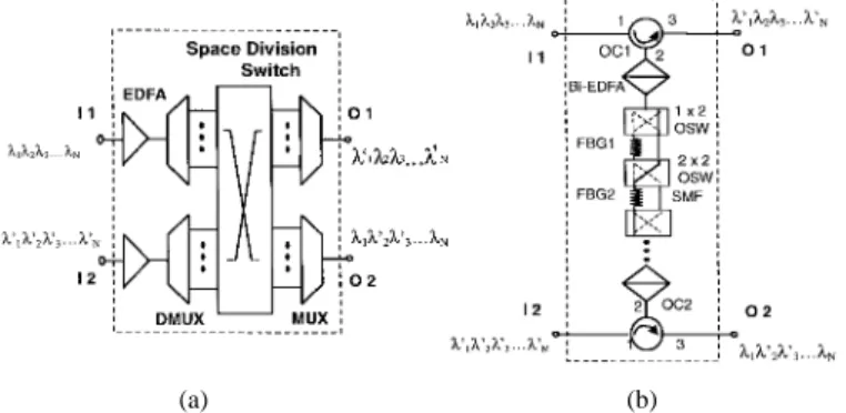
N OPTICAL networks usingwavelength-division-multiplexed (WDM) technology, an optical cross-connect device (OXC) is essential equipment for wavelength add/drop and routing. Transparent to signal format to a certain extent, the OXC’s allows the optical network to be reconfigured on a wavelength-by-wavelength basis to interchange and optimize traffic patterns, provide the routing function, facilitate network growth, and enhance network survivability [1]. OXC’s can be used to replace digital XC systems in high-speed transport networks [2], or to be utilized as switching core of ultrahigh-speed ATM cross-connects [3]. Fig. 1(a) shows a conventional reconfigurable 2 2 OXC. A space division switch is inserted in between two WDM multiplexer and demultiplexer pairs to select, interchange, and rearrange WDM channels. Two
sets of WDM channels and
are the same wavelengths for the upper and lower fiber links, respectively. Though shown as a single block, the space division switch can be realized by a number of switches, each switching for a particular wavelength. Large power loss induced by the OXC can be compensated by the pre- and/or postamplifiers. However, the architecture may be expensive and complicated due to the requirement of additional space division switch components. The drawbacks of complicated designs and controls of these elements have to be resolved to broaden the application of OXC.
Recently, a reconfigurable wavelength-selective OXC based on fiber Bragg gratings (FBG’s) and optical switches (OSW’s) was proposed by us [4]. In general, this kind of 2 2 OXC for channels WDM system requires XC units and
Manuscript received December 1, 1998; revised April 19, 1999. The work of S.-K. Liaw and S. Chi was supported in part by the National Science Council, Taiwan, R.O.C., under Grant NSC-88-2215-E-009-007.
S.-K. Liaw and S. Chi are with the Institute of Electro-Optical Engineering, National Chiao-Tung University, Hsin-Chu 300, Taiwan R.O.C.
K.-P. Ho, L. K. Chen, and F. Tong are with the Department of Information Engineering, The Chinese University of Hong Kong, Shatin N.T., Hong Kong.
Publisher Item Identifier S 1041-1135(99)05923-6.
(a) (b)
Fig. 1. Schematic diagrams of (a) the conventional 22 2 OXC and (b) the proposed FBG based 22 2 OXC. OC: Optical circulator. FBGi: Fiber Bragg grating i. SMF: Single-mode fiber. Bi-EDFA: Bidirectional EDFA. OSW: Optical switch.
switches. Among channels, the in-line loss is nonuniform since the shortest path length needs round-trip 1 XC unit and the longest path length needs round-trip XC units. In this paper, the OXC device is integrated with optical limiting amplifiers (OLA’s) to provide a large input dynamic range [5] and function as a self-equalizer for the erbium-doped fiber amplifier (EDFA). System demonstration of two-channel 2.5 Gb/s over a 100-km of single-mode fiber (SMF) using the OXC is provided to confirm its feasibility.
II. OPERATION MECHANISM
Fig. 1(b) shows the schematic diagram of the proposed
2 2 OXC. Large OXC can use the device in
Fig. 1(b) as a building block [6]. There are two input ports of I1 and I2 as well as two output ports of O1 and O2 in the OXC. The OXC also consists of numbers of XC units and two sets of bidirectional EDFA’s (Bi-EDFA’s). Each XC unit includes one OSW, one short piece of SMF and one
FBG . The FBG is designed to match
to the WDM-channel signals of and transmitted in the upper and lower fiber link. Without wavelength interchange, all signals are reflected by the FBG’s due to the bar-state status of all the OSW’s and then travel back to port 3 of the corresponding OC1/OC2. In that case, all wavelength channels are called the passing channels. If wavelength interchange is
required, for example, the exchange of with ,
the OSW’s corresponding to FBG and FBG can be switched to the cross-state. In that case, , and will pass through the chain of XC units and exchange to another output port (I1 to O2, I2 to O1). The WDM channels other than , and are reflected by the corresponding FBG’s
LIAW et al.: HIGH-DYNAMIC-RANGE OPTICAL CROSS-CONNECT DEVICE 1055
Fig. 2. Experimental setup to demonstrate the 22 2 OXC. TLS: Tunable laser source. MOD: 2.5-Gb/s external modulator. VA: Variable optical atten-uator. OBPF: Optical bandpass filter. BERT: Bit-error-rate test set.
in the XC units and pass through via port I1 to O1 and port I2 to O2, respectively. Even if and , for example, appear simultaneously, because the interaction distance is very short and other reflections are small, Rayleigh back-scattering may induce negligible degradation. All WDM channels are amplified twice by the Bi-EDFA(s). The passing channels travel round-trip and are amplified twice by the same Bi-EDFA while the crossing channels are amplified once by each Bi-EDFA. For both cases, two Bi-EDFA’s act as the OLA’s to improve the input dynamic range and increase the link budget. The laser pump can be shared by two Bi-EDFA’s for cost saving. In the above implementation of the OXC, all passing channels are reflected by the corresponding FBG’s. In another implementation, the label of O1 and O2 can be interchanged and all passing channels (i.e., signals from I1 to new O1 or from I2 to new O2) do not interact with the corresponding FBG’s, but rather the crossing channels interact with the corresponding FBG’s.
III. EXPERIMENTAL SETUP
The functionality of the OXC was demonstrated using the experimental setup in Fig. 2. Two tunable laser sources (TLS1 and TLS2) with the central wavelengths of 1557.1 and 1559.4 nm were connected to a 50/50 directional coupler and then externally modulated by a LiNbO3 intensity modulator using 2.5-Gb/s 2 1 PRBS. Two spools of SMF, each having 100 km in length, were located after the OXC. Two EDFA’s have a saturated output power of 9–10 dBm were used to compensate for the fiber loss. The optical bandpass filters (OBPF’s) with 3-dB bandwidth of 1.3 nm were used to filter out the amplified spontaneous emission (ASE) noise. The interport insertion loss and isolation of each OC is 1.0 and 47 dB. The FBG1 and FBG2 have a 3-dB bandwidth of 0.2 nm, reflectivity of over 99.95% and central reflective wavelengths matched to those of TLS1 and TLS2.
IV. RESULTS AND DISCUSSION
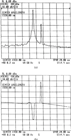
When and from TLS1 and TLS2 are launched from
I1, Fig. 3(a) shows the passing signal of 1557.1 nm observed
(a)
(b)
Fig. 3. Optical spectra of (a) the passing signal of 1557.1 nm at port O1 and (b) the crossing signal of 1559.4 nm at port O2. The insertion loss of the OXC for both the passing and crossing signals is about 2.5 dB. No Bi-EDFA was used during spectra measurement.
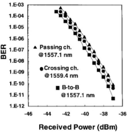
at O1 and Fig. 3(b) is the crossing signal of 1559.4 nm observed at O2. The insertion loss of the OXC for both the passing and crossing signals is about 2.5 dB. No Bi-EDFA was used during measurement to estimate the insertion loss of OXC. Fig. 4 shows that the input dynamic range for the OLA integrated OXC is over 20 dB both for the dual-pass (for passing signal) and cascaded (for crossing signal) Bi-EDFA’s. The output power variation between passing and crossing signals is less than 2.5 dB ranging from of 25 to 0 dBm. The feature makes the OXC act as a self-equalizer for WDM channels. The dynamic range of a conventional single-pass EDFA is only 8.5 dB as shown in Fig. 4. Fig. 5 shows the bit-error rate (BER) as a function of the received optical power for the baseline (0 km) at 1557.1 nm, passing signal (100 km) at 1557.1 nm and crossing signal (100 km) at 1559.4 nm. The power penalties are 1.0 and 0.6 dB for passing and crossing signals, respectively. Power penalty of the crossing and passing signals may be attributed to the accumulated ASE from two EDFA’s and the reflection of ASE/signals from FC/PC connectors inside the OXC. The angled-physical-connected (APC) connectors can be used to suppress the unwanted back reflections.
1056 IEEE PHOTONICS TECHNOLOGY LETTERS, VOL. 11, NO. 8, AUGUST 1999
Fig. 4. The output power versus input power for the dual-pass Bi-EDFA, cascaded two Bi-EDFA’s, and one conventional EDFA, respectively.
Fig. 5. Measured BER performance of the back-to-back signal at 1557.1 nm, passing signal (100 km) at 1557.1 nm and crossing signal (100 km) at 1559.4 nm using OXC.
Homodyne crosstalk, having the same wavelength as the signal, will cause severe system performance degradation in optical networks by beating with the desire channel [7]. Fig. 3(a) shows optical spectrum measured at O1 port when there are no other optical signals fed from the I2 port, there is about 25-dB heterodyne crosstalk from 1559.4 nm to the passing channel of 1557.1 nm due to the reflection from connectors and Rayleigh backscattering. For a crossing channel of 1559.4 nm, the heterodyne crosstalk level induced from 1557.1 nm is lower then the ASE floor. On the other hand, when two other signals from TLS1 and TLS2 are launched into the I2 port, the OXC will introduce 33 dB, corresponding to 0.05% ( 99.95%) relative power, of homodyne crosstalk to contaminate the passing channel of 1557.1 nm generates by the TLS1. The tolerable homodyne and heterodyne crosstalk level is much larger than 25 dB [7] and 33 dB [8], respectively. However, homodyne crosstalk may limit the usable bandwidth of FBG [9]. If another channel
wavelength of 1559.4 nm is fed from port I2, homodyne crosstalk of 25 dB is induced and may generate a power penalty of about 0.5 dB [7]. This power penalty can be reduced further by eliminate reflection from optical connectors and components. However, homodyne crosstalk may limit the abil-ity to cascade many OXC’s simultaneously. If the maximum
tolerable homodyne crosstalk is and the homodyne
crosstalk in each stage is , the maximum number of
cascaded OXC’s is ( , corresponding to 10
for the proposed OXC.
V. CONCLUSION
By integrated with OLA’s, a 2 2 OXC based on FBG’s is investigated and demonstrated. The OXC has 20-dB input dynamic range and small power penalty of 0.6 and 1.0 dB for the crossing and passing channels in a two-channel 2.5-Gb/s 100-km system demonstration. With the advantages of low channel crosstalk, high dynamic range, uniform loss spectrum for WDM channels, simple operation mechanism and low cost, the OXC could provide more reconfiguration flexibility and network survivability for WDM networks.
ACKNOWLEDGMENT
The experimental work of this paper was conducted in the Lightwave Communication Laboratory, Department of Information Engineering, The Chinese University of Hong Kong, Hong Kong.
REFERENCES
[1] C. A. Brackett, Foreward—Is there an emerging consensus on WDM networking?” (special issue on multiwavelength optical technology and networks) J. Lightwave Technol., vol. 14, pp. 936–941, June 1996. [2] S. Johansson, M. Lindblom, P. Granestrand, B. Lagerstrom, and L.
Thylen, “Optical cross-connect system in broadband networks: System concept and demonstrator description,” J. Lightwave Technol., vol. 11, pp. 688–694, May/June 1993.
[3] J. M. Gabriagues and J. B. Jacob, “Photonic ATM switching matrix based on wavelength routing,” in Proc. SPIE, Photon. Switch., Minsk, Ukraine, 1992, vol. 1807, pp. 355–359.
[4] S.-K. Liaw, K.-P. Ho, and S. Chi, “Multichannel add/drop and cross-connect using fiber Bragg gratings and optical switches,” Electron. Lett., vol. 34, pp. 1601–1603, 1998.
[5] S.-K. Liaw, K.-P. Ho, L. K. Chen, F. Tong, and S. Chi, “Fiber Bragg gratings based multiwavelwngth cross connect device with high dynamic range,” in 1999 Conf. Optical Fiber Communication (OFC99), San Diego, CA, paper WM42.
[6] Y. K. Chen and C. C. Lee, “Fiber Bragg grating-based large nonblocking multiwavelength cross-connect,” J. Lightwave Technol., vol. 16, pp. 1746–1756, Oct. 1998.
[7] K.-P. Ho, “Analysis of homodyne crosstalk in optical neyworks using Gram–Charlier series,” J. Lightwave Technol., vol. 17, pp. 149–153, Jan. 1999.
[8] K.-P. Ho and S.-K. Liaw, “Demultiplexer crosstalk rejection require-ments for hybrid WDM system with analog and digital channels,” IEEE
Photon. Technol. Lett., vol. 10, pp. 737–739, May 1998.
[9] R. J. S. Pedersen and B. F. Jørgensen, “Impact of coherent crosstalk on usable bandwidth of a grating-MZI based OADM,” IEEE Photon.