A Full duplex radio-over-fiber link
with Multi-level OFDM signal via a
single-electrode MZM and wavelength reuse with a
RSOA
Wen-Jr Jiang1, Chun-Ting Lin2*, Po-Tsung Shih1, Jason (Jyehong) Chen1, Peng-Chun Peng3, and Sien Chi1,4, Fellow, OSA
1 Department of Photonics and Institute of Electro-Optical Engineering, National Chiao Tung University, Hsinchu,
Taiwan 300, R.O.C.
2 College of photonics, National Chiao Tung University, Tainan 711, Taiwan, R.O.C.
3 Department of Electro-Optical Engineering, National Taipei University of Technology, Taipei 106, Taiwan, R.O.C. 4 Department of Photonics Engineering, Yuan Ze University, Chung Li 320, Taiwan, R.O.C.
*jinting@mail.nctu.edu.tw
Abstract: This work demonstrates the feasibility of a full duplex Radio-over-fiber (RoF) link employing multi-level OFDM signal via a single-electrode Mach-Zehnder modulator and wavelength reuse for uplink utilizing a reflective semiconductor optical amplifier (RSOA). A High spectral efficiency 5-Gb/s 16-QAM OFDM signal with frequency multiplication for the RoF downstream link is demonstrated, and negligible penalty is achieved after 25-km standard single mode fiber transmission. Furthermore, wavelength reuse for a 1.25-Gb/s OOK signal via a RSOA for the upstream link is also demonstrated with a receiver penalty of less than 0.5 dB following 25-km SMF transmission.
©2010 Optical Society of America
OCIS codes: (060.5625) Radio frequency photonics; (060.4510) Optical communications;
(060.2360) Fiber optics links and subsystems.
References and links
1. Z. Jia, J. Yu, G. Ellinas, and G. K. Chang, “Key enabling technologies for optical-wireless networks: optical millimeter-wave generation, wavelength reuse and architecture,” J. Lightwave Technol. 25(11), 3452–3471 (2007).
2. M. Sauer, A. Kobyakov, and J. George, “Radio over fiber for picocellular network architectures,” J. Lightwave Technol. 25(11), 3301–3320 (2007).
3. J. Yu, Z. Jia, L. Yi, G. K. Chang, and T. Wang, “Optical millimeter wave generation or up-conversion using external modulators,” IEEE Photon. Technol. Lett. 18(1), 265–267 (2006).
4. C. S. Choi, Y. Shoji, and H. Ogawa, “Millimeter-wave fiber-fed wireless access system based on dense wavelength-division-multiplexing networks,” IEEE Trans. Microw. Theory Tech. 56(1), 232–241 (2008). 5. Z. Xu, X. Zhang, and J. Yu, “Frequency upconversion of multiple RF signals using optical carrier suppression
for radio over fiber downlinks,” Opt. Express 15(25), 16737–16747 (2007).
6. J. M. Tang, P. M. Lane, and K. A. Shore, “Transmission performance of adaptively modulated optical OFDM signals in multimode fiber links,” IEEE Photon. Technol. Lett. 18(1), 205–207 (2006).
7. L. Chen, J. G. Yu, S. Wen, J. Lu, Z. Dong, M. Huang, and G. K. Chang, “A Novel scheme for seamless integration of RoF with centralized lightwave OFDM WDM-PON system,” J. Lightwave Technol. 27(14), 2786– 2791 (2009).
8. Z. Jia, J. Yu, and G. K. Chang, “A full-duplex radio-over-fiber system based on optical carrier suppression and reuse,” IEEE Photon. Technol. Lett. 18(16), 1726–1728 (2006).
9. Z. Dong, J. Lu, Y. Pi, X. Lei, L. Chen, and J. Yu, “Optical millimeter-wave signal generation and wavelength reuse for upstream connection in radio-over-fiber systems,” J. Opt. Netw. 7(8), 736–741 (2008).
10. J. Yu, M. Huang, Z. Jia, T. Wang, and G. K. Chang, “A novel scheme to generate single-sideband millimeter-wave signals by using low-frequency local oscillator signal,” IEEE Photon. Technol. Lett. 20(7), 478–480 (2008).
11. H. Bao, and W. Shieh, “Transmission simulation of coherent optical OFDM signals in WDM systems,” Opt. Express 15(8), 4410–4418 (2007).
12. S. L. Jansen, I. Morita, T. C. W. Schenk, N. Takeda, and H. Tanaka, “Coherent optical 25.8-Gb/s OFDM transmission over 4160-km SSMF,” J. Lightwave Technol. 26(1), 6–15 (2008).
13. A. J. Lowery, L. B. Du, and J. Armstrong, “Performance of optical OFDM in ultralong-haul WDM lightwave
#115906 - $15.00 USD Received 18 Aug 2009; revised 4 Jan 2010; accepted 5 Jan 2010; published 26 Jan 2010 (C) 2010 OSA 1 February 2010 / Vol. 18, No. 3 / OPTICS EXPRESS 2710
systems,” J. Lightwave Technol. 25(1), 131–138 (2007).
14. C. T. Lin, Y. M. Lin, J. J. Chen, S. P. Dai, P. T. Shih, P. C. Peng, and S. Chi, “Optical direct-detection OFDM signal generation for radio-over-fiber link using frequency doubling scheme with carrier suppression,” Opt. Express 16(9), 6056–6063 (2008).
15. V. J. Urick, J. X. Qiu, and F. Bucholtz, “Wide-band QAM-over-fiber using phase modulation and interferometric demodulation,” IEEE Photon. Technol. Lett. 16(10), 2374–2376 (2004).
16. M. Kavehrad, E. Savov;“Fiber-Optic Transmission of Microwave 64-QAM Signals,” IEEE J. Sel. Areas in Commun. 8(7), 1320–1326 (1990).
17. C. Lim, M. Attygalle, A. Nirmalathas, D. Novak, and R. Waterhouse, “Analysis of Optical Carrier-to-Sideband Ratio for Improving Transmission Performance in Fiber-Radio Links,” IEEE Trans. Microw. Theory Tech.
54(5), 2181–2187 (2006).
1. Introduction
The integration of optical and wireless system, i.e. the hybrid access networks, has attracted significant interest and is believed to be one of the most promising candidates for increasing the existing capacity and mobility for future access networks [1-2]. Radio-over-fiber (RoF) systems, which utilize the huge bandwidth offer by fiber and minimizes the cost of the base station and shift the system complexity to central office, are considered to be an viable and critical technology in future broadband wireless communication system [1–10]. Since orthogonal frequency division multiplexing (OFDM) signals have been widely utilized in wireless communication due to their robustness against multipath fading and feasibility of multi-level format, it is of utmost importance for RoF systems to support the OFDM format to extent transmission distance over fiber and air links with centralized signal processing at the central office.
Due to high tolerance against fiber chromatic dispersion and polarization-mode dispersion, optical OFDM systems have recently attracted a lot of attention for high-capacity long-haul communication, multimode fiber links, and plastic optical-fiber link [6,7,11]. Typically, optical OFDM systems can be categorized as coherent detection (CO) or direct detection (DD) systems. For a CO-OFDM system, the optical OFDM signal is transmitted with optical carrier suppression. Therefore, a local oscillator is needed at the receiver side. Compared with the DD-OFDM system, the CO-OFDM system provides better performance and is a promising candidate for future long-haul high-capacity communication systems [12-13]. However, phase noise and frequency offset of the local oscillator makes CO-OFDM systems very complex and unsuitable for RoF systems. For a DD-OFDM system, the optical OFDM signal is transmitted along with the carrier and can be directly converted to an electrical OFDM signal via a photodiode without a local oscillator. Therefore, DD-OFDM systems are simple and well-suited for cost-sensitive RoF systems.
Conventionally, optical DD-OFDM signals are generated based on double-sideband (DSB) or single-sideband (SSB) modulation schemes via an external Mach-Zehnder modulator (MZM) [13]. However, both DSB and SSB modulation approaches suffer from inferior sensitivities because the optical modulation index (OMI) is limited. Additionally, the
DSB modulation signal undergoes performance fading due to fiber dispersion. Recently, several schemes have been developed to overcome the issues of limited OMI and dispersion-induced fading [14]. However, a sophisticated dual-parallel MZM is needed to generate DD-OFDM signals [14].
This work presents a novel method for multi-level DD-OFDM signal generation using a single-electrode MZM based on the DSBCS modulation scheme. With the bias set at the null point, the MZM is operated in the linear region of the E-field to mitigate the nonlinear distortion caused by the high peak-to-average-power ratio (PAPR) of OFDM signals. Furthermore, a frequency multiplication scheme is employed to reduce the bandwidth requirement of the optical OFDM transmitter, which is an important issue to millimeter-wave RoF systems. Moreover, wavelength reuse is achieved for uplink signals at the base station. In this work, both a 5-Gb/s 16-QAM OFDM signal using the proposed transmitter for RoF downstream link and a 1.25-Gb/s on-off-keying (OOK) signal via a reflective semiconductor
#115906 - $15.00 USD Received 18 Aug 2009; revised 4 Jan 2010; accepted 5 Jan 2010; published 26 Jan 2010 (C) 2010 OSA 1 February 2010 / Vol. 18, No. 3 / OPTICS EXPRESS 2711
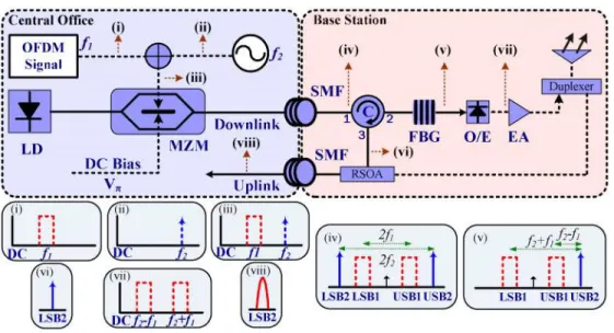
Fig. 1. Conceptual diagram of the proposed OFDM-RoF system. (i)(ii)(iii)(vi): Electrical spectra. (iv)(v)(vi)(viii): Optical spectra. (LD: laser diode, MZM: Mach-Zehnder modulator, SMF: single mode fiber, C: circulator, FBG: fiber Bragg grating, RSOA: reflective semiconductor optical amplifier, EA: electrical amplifier)
optical amplifier (RSOA) for upstream link are demonstrated. The penalty after transmission over 25-km single mode fiber (SMF) is negligible.
2. Concept of proposed OFDM system
Figure 1 schematically depicts the concept of the proposed optical OFDM signal generation using a single-electrode MZM. The MZM driving signal consists of an OFMD signal at a frequency of f1 and a sinusoidal signal with a frequency of f2, as indicated in insets (i)-(iii) in Fig. 1, respectively. To achieve the DSBCS modulation scheme, the MZM is biased at the null point. Inset (iv) of Fig. 1 presents the generated optical OFDM spectrum that has two upper-wavelength sidebands (USB1, USB2) and two lower-wavelength sidebands (LSB1, LSB2) with carrier suppression at the output of the MZM. After square-law photo detection, the beating terms of USB2 × LSB1 and USB1 × LSB2 generate electrical OFDM signals at the sum frequency (f2+f1), while the beating terms of USB2 × USB1 and LSB1 × LSB2 generate electrical OFDM signals at the difference frequency (f2-f1).
To provide wavelength reuse for the upstream data link at the remote node, one of generated optical subcarriers is filtered out for re-modulation via a RSOA. The remainder of the signals, which can generate two electrical OFDM signals at the sum and difference frequencies as shown in inset (vii) in Fig. 1, is sent to wireless applications. Notably, a frequency multiplication technique (up to 2 times) can be achieved by properly choosing frequencies of f1 and f2 to reduce the bandwidth requirement of the OFDM transmitter, which is crucial for radio-frequency (RF) OFDM signals exceeding 40 GHz because the frequency response of a typical commercial MZM is less than 40 GHz.
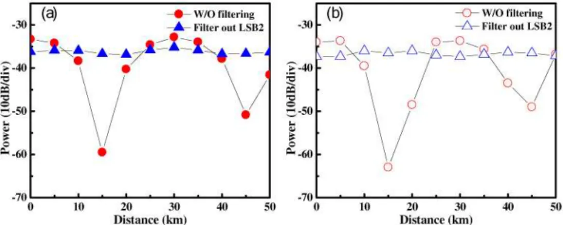
Filtering out of optical subcarrier not only provides an upstream light source but also eliminates performance fading due to fiber dispersion. As presented in Fig. 2(a), f1 and f2 located at frequencies of 3.7 GHz and 16.3 GHz, respectively, are used to simulate performance fading. The generated RF signal without removing LSB2 at the sum frequency of 20 GHz vanishes as the transmission length is 15 km. The reason is that there are two different sources generated the 20-GHz electrical RF signals. The cross terms of both USB2 × LSB1 and USB1 × LSB2 contribute to the power of the generated 20-GHz RF signal. After SMF transmission, the relative phase between the two generated cross-term RF signals changes with transmitted SMF length. As the relative phase is 180°, the electrical generated 20-GHz RF signal will vanish. If an optical filter is utilized to remove any of the four optical
#115906 - $15.00 USD Received 18 Aug 2009; revised 4 Jan 2010; accepted 5 Jan 2010; published 26 Jan 2010 (C) 2010 OSA 1 February 2010 / Vol. 18, No. 3 / OPTICS EXPRESS 2712
Fig. 2. (a) Simulation and (b) experimental results of RF performance fading versus SMF transmission distance.
Fig. 3. Experimental setup of the proposed system. (BERT: bit error rate test, BPF: band-pass filter)
subcarriers, 20-GHz RF signal fading with transmitted SMF length can be eliminated. Fig. 2 (b) plots the experimental results. As predicted by the simulation analysis, the experimental results show the same RF fading effect.
For the wireless channel, the signal will suffer inter-symbol-interference (ISI) caused by multi-path and loss. ISI can be resolved by cyclic prefix (CP) insertion and extra loss can be compensated by increasing the RF power. However, the multi-path fading and loss will induce additional penalty depend on wireless transmission length, frequency of wireless signal, antenna gain, etc. Because this manuscript focuses on fiber chromatic RF fading of the RoF system, the properties of wireless transmission are beyond the scope of this paper. 3. Experimental setup
Figure 3 depicts the experimental setup of the proposed OFDM signal generation. The OFDM signals applied to a X-cut single-electrode MZM are generated by an arbitrary waveform
#115906 - $15.00 USD Received 18 Aug 2009; revised 4 Jan 2010; accepted 5 Jan 2010; published 26 Jan 2010 (C) 2010 OSA 1 February 2010 / Vol. 18, No. 3 / OPTICS EXPRESS 2713
generator (AWG, Tektronix® AWG7102) using the Matlab® program. The single electro MZM's has bandwidth of 20 GHz, 20 dB extinction ratio and Vπ equals to 6 Volts. And the
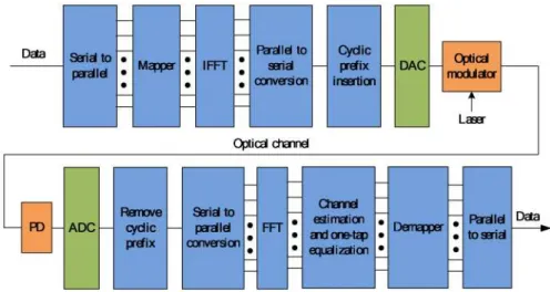
Fig. 4. Block diagrams of OFDM transmitter (a) and receiver (b). (IFFT: inverse fast Fourier transform, DAC: digital-to-analog converter, PD: photodiode, ADC: analog-to-digital converter, FFT: fast Fourier transform)
electrical signal send into the MZM is set at about 0.1 Vπ. The block diagram of the OFDM
transmitter consists of serial-to-parallel conversion, quadrature amplitude modulation (QAM) modulation, inverse fast Fourier transform (IFFT), cyclic prefix (CP) insertion, and digital-to-analog conversion (DAC), as shown in Fig. 4. The sampling rate and digital-to-digital-to-analog converter resolution of the AWG are 20 Gb/s and 8 bits, respectively. The IFFT size is 512. A 39.0625-MSym/s 16-QAM symbol is encoded at channels 80 – 111 (i.e., the subcarrier center frequency ranges from 3.125 to 4.3359375 GHz) with the remaining 480 channels set to zero.
Therefore, a 5-Gb/s 16-QAM OFDM signal that has 32 subcarriers and occupies a total bandwidth of 1.25 GHz can be generated at a center frequency of 3.7 GHz as shown in inset (i) in Fig. 3. The CP is set to 1/256 symbol time to combat fiber dispersion. After DAC, a sinusoidal signal with a frequency of 16.3 GHz is combined with the OFDM signal. The OFDM signal and the 16.3-GHz sinusoidal signal are then sent to the single-electrode MZM as shown in inset (ii) in Fig. 3. Inset (iii) in Fig. 3 presents the generated optical OFDM spectrum at the output of the MZM that has four sidebands.
At the base station, a fiber Bragg grating (FBG) filter is employed to remove the un-modulated LSB2 for the upstream data link as shown in inset (viii) in Fig. 3. The FBG reflection and transmission is shown in inset (iv) of Fig. 3. The 3-dB passband and stopband bandwidth of the FBG is about 4.5 GHz center at 1554.92nm with power suppression ratio of 25 dB. The LSB2 is then modulated with a 1.25-Gb/s on-off-keying (OOK) signal via a RSOA as shown in inset (ix) in Fig. 3. For the RSOA, the electrical bandwidth is 1.2 GHz, with −12 dBm input optical power. The bias voltage is set at 4 Volts and the driving voltage of the OOK signal is 2 Volts. After the FBG, the rest of the signal [inset (e)] is sent to photodiode, as shown in inset (v) in Fig. 3. After square-law photo detection, a 5-Gb/s 16-QAM OFDM signal at the sum frequency of 20 GHz is generated as shown in inset (vi) in Fig. 3. For RoF applications, this signal can be directly utilized for wireless transmission. To demodulate the signal, the OFDM signal is down-converted to 3.7 GHz by a 16.3 GHz oscillator and a mixer as shown in inset (vii) in Fig. 3. The waveform is captured by a digital oscilloscope (Tektronix® DPO 71254) with a 50-Gb/s sampling rate and a 3-dB bandwidth of 12.5 GHz. The block diagram of the typical OFDM receiver is shown in Fig. 4. An off-line Matlab® digital signal processing program is employed to demodulate the OFDM signal. This demodulation process includes synchronization, fast Fourier transform (FFT), one-tap equalization, and QAM symbol decoding. From the constellation of OFDM signal, error
#115906 - $15.00 USD Received 18 Aug 2009; revised 4 Jan 2010; accepted 5 Jan 2010; published 26 Jan 2010 (C) 2010 OSA 1 February 2010 / Vol. 18, No. 3 / OPTICS EXPRESS 2714
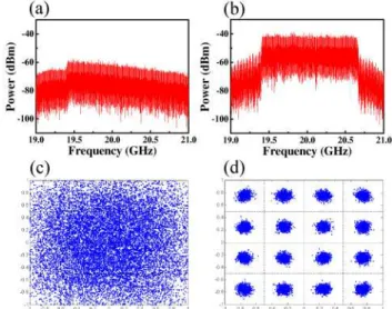
vector magnitude (EVM) can be obtained and then bit error rate (BER) is calculated from the measured EVM [15-16]. Notably, filtering out LSB2 can overcome the RF fading due to fiber dispersion. If LSB2 is not removed, the experimental results show similar outcomes with simulation. Without filtering out the optical sideband, the electrical signal power become very
Fig. 5. Experiment result of RF performance fading versus SMF transmission length.
Fig. 6. OPR versus measured receiver sensitivity at normalized optical power.
weak due to fading and the constellation is dominated by noise. Both the OFDM spectrum and 16-QAM constellation disappear after 15-km SMF transmission as shown in Fig. 5(a) and (c). However, the OFDM spectrum and 16-QAM constellation are successfully recovered as shown in Fig. 5(b) and (d) after LSB2 is filtered out.
4. Experimental results and discussion
Due to the narrow linear region of the MZM, the OFDM signal is weakly modulated. Therefore, for optical DD-OFDM systems, the relative intensity between the optical un-modulated subcarrier and optical OFDM-un-modulated subcarrier significantly influences on the performance of optical OFDM signals [17]. One of the advantages of the proposed OFDM transmitter is that the relative intensity between optical un-modulated subcarrier and OFDM-modulated subcarrier can be easily tuned by adjusting the individual amplitude of the
#115906 - $15.00 USD Received 18 Aug 2009; revised 4 Jan 2010; accepted 5 Jan 2010; published 26 Jan 2010 (C) 2010 OSA 1 February 2010 / Vol. 18, No. 3 / OPTICS EXPRESS 2715
sinusoidal signal and OFDM signal to optimize OFDM performance. The optical power ratio (OPR) of the optical subcarrier to the optical OFDM-modulated subcarrier is defined as
sub OFDM
OPR= P P (1)
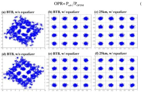
Fig. 7. Constellations of 5-Gb/s 16-QAM OFDM signals. The optical power is normalized to −15dBm before detection. (a)(b)(c): OFDM signals with LSB2 filtered out. (d)(e)(f): OFDM signals with OFDM-modulated LSB1 filtered out.
Fig. 8. BER curves of 5-Gb/s 16-QAM OFDM downlink signals.
where Psub and POFDM are the optical powers of optical un-modulated and OFDM-modulated
subcarriers, respectively. Figure 6 illustrates the receiver sensitivity of the OFDM signals versus different OPRs as optical powers of OFDM signals are normalized before detection.
For OFDM signals without filtering out LSB2, the optimal OPR is around 1 dB as shown in inset (b) in Fig. 6. However, as either LSB2 or LSB1 is filtered out, the optimal OPRs shift to 4 dB and −3 dB as shown in insets (c) and (a) in Fig. 6, respectively. As shown in Fig. 6, with same receiving power, because there are two copies of data received in the “without filter” conditions, it has the best back-to-back (BTB) BER performance. On the other hand, only one copy of data is received in either filtering out LS1 or LS2; therefore, they show worse BER performance. In this study, the un-modulated LSB2 subcarrier is filtered out at the base station for the upstream data link via RSOA and the optimal OPR is set at 4 dB. Figure 7 (a), (b) and (c) show the 16-QAM constellation diagrams of OFDM signals with LSB2
#115906 - $15.00 USD Received 18 Aug 2009; revised 4 Jan 2010; accepted 5 Jan 2010; published 26 Jan 2010 (C) 2010 OSA 1 February 2010 / Vol. 18, No. 3 / OPTICS EXPRESS 2716
removed in BTB without equalization, BTB with equalization and following 25-km SMF transmission with equalization, respectively. Figure 7(d), (e) and (f) plots the constellation diagrams under the same conditions but with LSB1 filtering out.
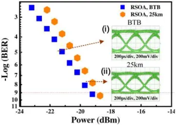
Fig. 9. BER curves of 1.25-Gb/s OOK uplink signals.
In BTB without equalization case, there is amplitude variation and phase offset for different subcarriers, so the radiated pattern appears. The training data is used to estimate of amplitude and phase response for different subcarriers and then equalization coefficient is calculated from response for different subcarriers. With proper equalization coefficient in frequency domain, the constellation diagram becomes clear. The constellation is still very clear after 25 km of SMF. After filtering out either LSB2 or LSB1, the generated OFDM signals do not suffer from RF periodic fading issue due to fiber dispersion. Only in-band distortion of the OFDM-encoded subcarrier caused by fiber dispersion is considered. Since the symbol rate of each subcarrier is only 39.0625 MSym/s and the CP of 1/256 symbol time is utilized, the fiber chromatic penalty can be ignored. Hence, clear constellations are observed after 25-km SMF transmission. Figure 8 shows the BTB and after transmission over 25-km SMF BER curves of the downstream 5-Gb/s 16-QAM OFDM signals using optimal OPRs. For optical downstream OFDM signals with LSB1 or LSB2 filtered out, the receiver sensitivity at a BER of 10−9 is −13.2 dBm for the BTB case. The penalty at a BER of 10−9 is negligible following 25-km SMF transmission. The un-modulated LSB2 is re-used for uplink data transmission and is modulated with the 1.25-Gb/s OOK signal via a RSOA. After transmission over 25-km SMF, the sensitivity penalty at a BER of 10−9 is less than 0.5 dB as shown in Fig. 9. Figure 9 also presents the eye diagrams of the uplink signal, the eye diagrams are observed without significant distortion.
4. Conclusion
With the rapid integration of optical and wireless systems, the OFDM format is particularly attractive for the hybrid system due to its resistance to multipath fading and feasibility of multi-level format. It is of utmost important for the RoF system to support the OFDM format to reduce the cost and complexity of the system. The proposed architecture utilizes a cost-effective single-electrode MZM based on DSBCS modulation scheme. The frequency multiplication (up to 2 times) with a carrier suppression technique is achieved to reduce the bandwidth requirement of OFDM transmitter. A highly spectral efficiency 5-Gb/s 16-QAM OFDM signal is successfully generated and transmitted over 25-km SMF with negligible sensitivity penalty. Furthermore, wavelength reuse for uplink data transmission via a RSOA is also demonstrated with a penalty of less than 0.5 dB.
#115906 - $15.00 USD Received 18 Aug 2009; revised 4 Jan 2010; accepted 5 Jan 2010; published 26 Jan 2010 (C) 2010 OSA 1 February 2010 / Vol. 18, No. 3 / OPTICS EXPRESS 2717
Acknowledgments
The authors would like to thank the National Science Council of the Republic of China, Taiwan, for financially supporting this research under Contract Nos. NSC 96-2221-E-155-038-MY2, NSC 97-2221-E-009-105-MY3, and NSC 96-2628-E-009-016-MY3.
#115906 - $15.00 USD Received 18 Aug 2009; revised 4 Jan 2010; accepted 5 Jan 2010; published 26 Jan 2010 (C) 2010 OSA 1 February 2010 / Vol. 18, No. 3 / OPTICS EXPRESS 2718