Comparisons on properties and growth mechanisms of carbon nanotubes
fabricated by high-pressure and low-pressure plasma-enhanced
chemical vapor deposition
Chao Hsun Lin
a,b,*, Shu Hsing Lee
a,b, Chih Ming Hsu
b, Cheng Tzu Kuo
aa
Department of Materials Science and Engineering, National Chiao Tung University, Taiwan
b
Materials Research Laboratories, ITRI, Taiwan
Available online 25 August 2004
Abstract
Effects of plasma pressure and the presence of nitrogen on growth of carbon nanotubes (CNTs) and their properties were studied by using microwave plasma chemical vapor deposition (MPCVD) (pressure=600–3300 Pa) and electron cyclotron resonance chemical vapor deposition (ECR-CVD) (pressure=0.3–0.6 Pa) systems. CH4/H2and CH4/N2were used as source gases, and Co as the catalyst. The structures and properties of CNTs were characterized by using field emission scanning electron microscopy (FE-SEM), transmission electron microscopy (TEM), Raman spectra, and field emission I–V measurements. The results show that CNTs made by higher plasma pressure system have a higher growth rate (typically 1–3 Am/min), smaller tube diameter, better field emission properties, and better tube quality. The growth rate is related to the availability of carbon source. The morphology change from spaghetti-like to well-aligned CNTs is discussed in terms of directed ions. The change in field emission properties is reasoned in terms of geometric enhancement factor and screening effect for different tube morphologies. The presence of nitrogen plasma can have the following effects: increasing tube diameter, increasing straightness of CNTs, forming of bamboo-like CNTs, deterioration of field emission properties, and shifting of Raman peak toward lower-frequency side (or increasing residual tensile stress).
D 2004 Elsevier B.V. All rigths reserved.
Keywords: Carbon nanotubes; Microwave plasma CVD; Electron cyclotron resonance CVD; Field emission; Growth mechanism
1. Introduction
Carbon nanotubes (CNTs) have been of great interest to scientists and industrial communities due to their unique properties and diverse applications (such as in nanoelec-tronics [1–3], scanning probes [4], supercapacitors [5,6], hydrogen storage[7–9], and as field emitters[10–12]) since their discovery by Iijima[13]in 1991. There are two basic types of techniques presently available for CNT fabrication: vaporization methods (e.g., arc discharge)[13 14]and laser
ablation [15]. Another type are chemical vapor deposition (CVD) methods in which the CNTs are synthesized by the catalytic decomposition of hydrocarbons over a transition metal catalyst [e.g., thermal CVD [16–20], hot filament chemical vapor deposition (HFCVD) [21], microwave plasma chemical vapor deposition (MPCVD) [22–27], and electron cyclotron resonance chemical vapor deposition (ECR-CVD)[28–30]. According to the above researches, it is well known that the structures and properties of CNTs are highly process-dependent. The arc discharge and laser ablation methods can grow both single-walled nanotubes (SWNTs) and multiwalled nanotubes (MWNTs). In contrast, the CVD methods are generally more favored to synthesize the well-aligned or spaghetti-like MWNTs.
The vaporization methods (e.g., arc discharge and laser ablation methods) involve a solid source material as well as a
0925-9635/$ - see front matterD 2004 Elsevier B.V. All rigths reserved. doi:10.1016/j.diamond.2004.06.033
* Corresponding author. Materials Research Laboratory, ITRI, V200, 195-5 Chung Hsing Rd., Section 4, Chutung, Hsinchu 310, Taiwan. Tel.: +886 3 5914174; fax: +886 3 5820207.
E-mail addresses: [email protected] (C. Hsun Lin), [email protected] (C. Tzu Kuo).
gaseous one. In these cases, the vaporized solid is absorbing and reacting as well, so the processes are more difficulty to control [31]. Moreover, there are other disadvantages of these vaporization methods such as high equipment invest-ment and low CNT yield rate. In contrast, the CVD methods have many advantages such as relatively low equipment cost, high CNT yield rate, and well-aligned and patterned CNT arrays during in situ growth. So, the CVD methods have received more investigations recently. In this study, two kinds of plasma CVD systems (MPCVD and ECR-CVD) were used for CNT deposition. The typical working pressures for both systems are in the range of 600–3300 and 0.3–0.6 Pa, respectively. These relatively high-pressure and low-pressure plasma conditions have been demonstrated to result in significant differences in morphologies, growth rate, and field emission properties. The purposes of this study were to investigate the important parameters that control the CNTs formation, and then to examine their properties, structures, and growth mechanisms.
2. Experimental
The MPCVD and ECR-CVD systems with 2.45-GHz (12 cm wavelength) microwave were used in this study as typical high-pressure and low-pressure plasma-enhanced CVD processes, respectively. Their operating pressures have three- to four-order differences in magnitude, ranging from 600–3300 Pa for MPCVD to 0.3–0.6 Pa for ECR-CVD. In MPCVD, the standing wave is coupled by the metal quarterwave cavity [31] and formed a plasma ball with diameter of about 3 cm at the center of a quartz tube. The sample is immersed in plasma during catalyst pretreat-ment and CNT deposition. The substrate is heated by plasma collision and its temperature is controlled by adjusting the holder position with respect to the center of the plasma ball. In ECR-CVD, a strong magnetic field B is established parallel to the direction of the microwave beam. An 875-G magnetic field is applied to maintain the ECR conditions. An additional electrical heating coil is provided in the substrate holder to maintain the required temperatures to activate the catalyst on the substrate surface for CNT
formations. Furthermore, the substrate-negative DC bias in the proper range ( 50 to 200 V) is generally applied for effective CNT grown by ECR-CVD method. It is essential to enhance the required bombardment energy and attract more positive depositing species without causing sputtering effect.
The sputtered Co films on Si substrates were used as catalysts, which were pretreated with hydrogen plasma before CNT depositions. To examine the effect of the presence of N2, both CH4/H2 and CH4/N2 are used as reaction gases at temperatures around 630–650 8C. The detailed catalyst pretreatment and deposition conditions are shown in Table 1. The deposited nanostructures were characterized by field emission scanning electron microscopy (FE-SEM), transmission electron microscopy (TEM), and Raman spectroscopy. The field emission property was evaluated by I–V measurement at a vacuum of 10 4Pa with a 2-mm-diameter flat-tip anode electrode and 100-Am anode– cathode separations.
3. Results and discussion
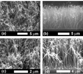
3.1. Film morphologies by MPCVD and ECR-CVD The SEM micrographs of the CNTs by MPCVD are shown inFig. 1.Fig. 1a and b shows the top and side views of the CNTs with CH4/H2as source gas, respectively. The corresponding micrographs for the CNTs with CH4/N2 as source gas are shown in Fig. 1c and d. These figures show that the typical spaghetti-like CNTs can be fabricated by MPCVD, although the well-aligned CNTs can also be grown under certain deposition conditions. In terms of the effect of replacing hydrogen with nitrogen, it is shown that the CNTs in Fig. 1d (30–50 nm in diameter) are relatively larger in diameter and straighter in shape than those in Fig. 1b (10–30 nm in diameter). From the previous studies
[27,30], introduction of nitrogen in the MPCVD system is a favored condition to form so-called bbamboo-like MWNTsQ instead of bhollow-like MWNTs.Q
Fig. 2 shows the SEM micrographs of CNTs by ECR-CVD.Fig. 2a–c shows morphologies of CNTs with CH4/H2
Table 1
Specimen designations and deposition conditions of CNTs by MPCVD and ECR-CVD methods
Designation MPCVD ECR-CVD
Pretreatment Deposition Pretreatment Deposition
MP-1 MP-2 ECR-1 ECR-2
Catalyst (thickness, nm) Co (7.5) Co (100)
Gas sources H2 CH4/H2 CH4/N2 H2 CH4/H2 CH4/N2
Flow rate (sccm) 100 10/100 10/100 20 18/2 18/2
Working pressure (Pa) 670 2130 2130 0.3 0.3 0.3
Microwave power (W) 500 800 800 800 800 800
DC bias (V) N/A (self-biasing) 100 100 200
Temperature (8C) ~650 (plasma heating) ~650 ~630 ~630
as source gas, where the inset inFig. 2a corresponds to a micrograph at higher magnification andFig. 2b is the image of pressed CNTs. There is no significant difference in appearance for CNTs with CH4/N2 as source gas when comparingFig. 2d with others, although the tip shapes are pyramid-like instead of round-like. It is obvious that CNTs by ECR-CVD in Fig. 2 are much more well-aligned, perpendicular to the substrate and greater in diameter than those by MPCVD inFig. 1. The diameters of CNTs with CH4/H2and CH4/N2as source gases in Fig. 2c and d are about 30–60 and 40–80 nm, respectively. However, it is interesting to note that the CNTs by ECR-CVD are all bamboo-like in structure and tip growth in model, whether
nitrogen is present or not. The TEM image shown inFig. 3is a bamboo-like CNT grown by ECR-CVD. Its compartment thickness is generally thinner than that of bamboo-like CNTs grown by MPCVD.
3.2. Growth mechanisms of CNTs under high-pressure and low-pressure plasma CVD
In order to study growth mechanisms, it is required to examine the differences in plasma generation between MPCVD (high gas pressure) and ECR-CVD (low gas pressure). When compared to the MPCVD system, the main feature of the ECR-CVD system is much greater in terms of mean free path of ion collisions. This is due to its lower gas pressure and electron cyclotron resonance effect, and the more directional ionized species caused by strong magnetic field (B=875 G) and bias potential [31]. This brings the ECR source many advantages, such as high plasma density (typically 1012 cm 3), high ionization fraction (approach unity), and perpendicularly directed ions with depositing species and bombardment energy.
The CNT growth rate by MPCVD is about 1–3 Am/min, in contrast to ~0.1 Am/min by ECR-CVD. This can be due to more depositing species for the CNT growth under higher plasma pressure. It also implies that the mass transport is the rate-controlling step of the deposition process. The
ran-Fig. 2. SEM micrographs of CNTs by ECR-CVD with Co as catalyst. (a) Top view and the inset at high magnification: CH4/H2plasma (specimen
ECR-1). (b) Side view of the pressed CNTs: CH4/H2plasma (specimen
ECR-1). (c) 458 Side view: CH4/H2plasma (specimen ECR-1). (d) 458 Side
view: CH4/N2plasma (specimen ECR-2).
Fig. 3. TEM micrograph of the CNTs by ECR-CVD with Co as catalyst, under CH4/H2plasma (specimen ECR-1).
Fig. 1. SEM micrographs of CNTs by MPCVD with Co as catalyst. (a) Top view: CH4/H2 plasma (specimen MP-1). (b) Side view: CH4/H2 plasma
(specimen MP-1). (c) Top view: CH4/N2plasma (specimen MP-2). (d) Side
view: CH4/N2plasma (specimen MP-2).
Fig. 4. Raman spectra of the Co catalyst-assisted CNTs. (a) MPCVD, CH4/
H2plasma (specimen MP-1). (b) MPCVD, CH4/N2plasma (specimen
MP-2). (c) ECR-CVD, CH4/H2plasma (specimen ECR-1). (d) ECR-CVD, CH4/
domly directed motion of the depositing species in MPCVD is believed to cause attachment of carbon atoms on the catalyst surface at relative broad directions to form the spaghetti-like CNTs. In contrast, the perpendicularly direc-ted ions with depositing species at higher bombardment energy in the ECR-CVD (low-pressure plasma) system can be the cause of well-aligned CNTs.
3.3. Raman spectra and field emission properties
Fig. 4 depicts the micro-Raman spectra of CNTs by MPCVD (curves (a) and (b)) and ECR-CVD (curves (c) and (d)). Curves (b) and (d) correspond to CNTs by replacing H2 with N2 as one of the source gases, where the D-line corresponds to sp3bonding as well as defects of CNTs such as pentagon and heptagon; and G-line corresponds to sp2 bonding of crystalline graphene sheets. The D-line and G-line for curves (a), (b), (c), and (d) are (1356, 1597), (1344, 1589), (1355, 1593), and (1351, 1589) cm 1, respectively. The corresponding I( G)/I(D) ratios are 0.90, 1.13, 0.68, and 0.74, respectively. It was reported that the tensile stress in the carbon-based films can shift Raman peak positions to a lower-frequency side[28,32]. In other words, the introduc-tion of nitrogen into both high-pressure and low-pressure plasma CVD may cause more tensile residual stress in the deposited CNTs structures that ascribed to more defects in the graphene layers due to higher bombardment energy of nitrogen ions than hydrogen. The results of I( G)/I(D) ratios indicate that the CNTs by MPCVD have a better nanotube quality than those by ECR-CVD. It may be also due to higher ion bombardment energy in ECR-CVD circumstance that results in more defects in the ECR-CVD-grown CNTs. However, if we compare the I( G)/I(D) ratio by the same process of MPCVD or ECR-CVD, we can find that the introduction of nitrogen in both processes increased the I( G)/ I(D) ratio. Does this seem unreasonable? But after carefully examining the deposits, we found that the presence of nitrogen in the plasma derived cleaner deposited films by either MPCVD or ECR-CVD. It indicates that the higher bombardment energy of nitrogen ions/atoms could etch out the amorphous carbon.
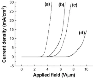
Fig. 5illustrates the J–E curves of the CNTs by MPCVD (curves (a) and (b)) and ECR-CVD (curves (c) and (d)), in which curves (b) and (d) correspond to CNTs by replacing H2with N2 as one of the source gases, respectively. It is obvious that the CNTs by MPCVD with or without the presence of nitrogen show better field emission properties. The turn-on electric fields (Eturn-on), defined as the applied field strength at a current density J=1 AA/cm2, are 2.48, 3.41, 3.54, and 5.53 V/Am for curves (a)–(d), respectively. The threshold electric fields (Eth), defined as the applied field strength at J=10 mA/cm2, are 3.98, 6.01, 6.62, and 9.61 V/Am for curves (a)–(d), respectively. On field emission properties of CNTs, the results indicate that the CNTs by MPCVD (high-pressure plasma) are better than CNTs by ECR-CVD (low-pressure plasma), and the CNTs
with the presence of hydrogen in plasma are better than with nitrogen. The major reasons may be attributed to: (1) the higher aspect ratios and so higher shape enhancement factor b of CNTs by MPCVD or without the presence of nitrogen plasma; (2) effectively increasing the emitting sites by exposing defects on the tube stems of the spaghetti-like CNTs; and (3) greater blocking or screening effects from the catalysts at the tips and the neighboring well-aligned CNTs by ECR-CVD [29].
4. Conclusions
The MPCVD (higher plasma pressure) and ECR-CVD (lower plasma pressure) with and without the presence of nitrogen were used to study the effects of plasma pressure and the presence of nitrogen on growth of CNTs. The high-pressure plasma system can provide a greater amount of depositing carbon-based species, but in a random fashion of motion. It results in a higher CNT growth rate and spaghetti-like CNT formation. The low-pressure plasma system (ECR-CVD) with proper negative bias application can produce more directed positive depositing species with higher kinetic energy. It gives rise to the well-aligned tip growth CNTs. The CNTs by higher plasma pressure system without the presence of nitrogen have better field emission properties and tube quality (higher Raman I( G)/I(D) ratios).
Acknowledgements
The authors would like to acknowledge the support of the National Science Council of Taiwan under contract nos. NSC 92-2216-E-009-009, NSC 92-2216-E-009-010, and NSC 92-2120-M009-001.
Fig. 5. Field emission J–E curves of the Co catalyst-assisted CNTs. (a) MPCVD, CH4/H2plasma (specimen MP-1). (b) MPCVD, CH4/N2plasma
(specimen MP-2). (c) ECR-CVD, CH4/H2plasma (specimen ECR-1). (d)
References
[1] P.G. Collins, A. Zettl, H. Bando, A. Thess, R.E. Smalley, Science 278 (1997) 100.
[2] R. Martel, T. Schmidt, H.R. Shea, T. Hertel, P.H. Avouris, Appl. Phys. Lett. 73 (1998) 2447.
[3] L. Roschier, J. Penttila, M. Martin, P. Hskonen, M. Paalanen, U. Tapper, E.I. Kauppinen, C. Journet, P. Bernier, Appl. Phys. Lett 75 (1999) 728.
[4] H. Dai, J.H. Hafner, A.G. Rinzler, D.T. Rinzler, D.T. Colbert, R.E. Smalley, Nature 384 (1996) 147.
[5] G. Che, B.B. Lakshmi, E.R. Fisher, C.R. Martin, Nature 393 (1998) 346.
[6] E. Frackowiak, F. Beguin, Carbon 39 (2001) 937.
[7] A. Zuttel, Ch. Nutzenadel, P. Sudan, Ph. Mauron, Ch. Emmenegger, S. Rentsch, L. Schlapbach, A. Weidenkaff, T. Kiyobayashi, J. Alloys Compd. 330–332 (2002) 676.
[8] N. Nishimiya, K. Ishigaki, H. Takikawa, M. Ikeda, Y. Hibi, T. Sakakibara, A. Matsumoto, K. Tsutsumi, J. Alloys Compd. 339 (2002) 275.
[9] A. Zuttela, P. Sudana, Ph. Maurona, T. Kiyobayashib, Ch. Emmeneggera, L. Schlapbacha, Int. J. Hydrogen Energy 27 (2002) 203.
[10] W.I. Milne, K.B.K. Teo, M. Chhowalla, G.A.J. Amaratunga, D. Pribat, P. Legagneux, G. Pirio, V.T. Binh, V. Semet, Curr. Appl. Phys. 2 (2002) 509.
[11] J.E. Junga, Y.W. Jina, J.H. Choia, Y.J. Parka, T.Y. Kob, D.S. Chunga, J.W. Kima, J.E. Janga, S.N. Chaa, W.K. Yia, S.H. Chob, M.J. Yoonb, C.G. Leeb, J.H. Youb, N.S. Leee, J.B. Yooc, J.M. Kima, Physica, B 323 (2002) 71.
[12] J.M. Bonard, M. Croci, C. Klinke, R. Kurt, O. Noury, N. Weiss, Carbon 40 (2002) 1715.
[13] S. Iijima, Nature 354 (1991) 56.
[14] T.W. Ebbesen, P.M. Ajayan, Nature 358 (1992) 220.
[15] A. Thess, R. Lee, P. Nikolaev, H. Dai, P. Petit, J. Robert, C. Xu, Y.H. Lee, S.G. Kim, A.G. Rinzler, D.T. Colbert, G. Scuseria, D. Tomanek, J.E. Fisher, R.E. Smalley, Science 273 (1996) 483.
[16] J. Li, C. Papadopoulos, J.M. Xu, M. Moskovits, Appl. Phys. Lett. 75 (1999) 367.
[17] C.J. Lee, J. Park, Appl. Phys. Lett. 77 (2000) 3397. [18] Y. Avigal, R. Kalish, Appl. Phys. Lett. 78 (2001) 2291.
[19] J.I. Sohn, S. Lee, Y.H. Song, S.Y. Choi, K.I. Cho, K.S. Nam, Appl. Phys. Lett. 78 (2001) 901.
[20] Y.Y. Wei, G. Eres, V.I. Merkulov, D.H. Lowndes, Appl. Phys. Lett. 78 (2001) 1394.
[21] Z.F. Ren, Z.P. Huang, J.W. Xu, J.H. Wang, P. Bush, M.P. Siegal, P.N. Provencio, Science 282 (1998) 1105.
[22] S.H. Tsai, C.W. Chao, C.L. Lee, H.C. Shih, Appl. Phys. Lett. 74 (1999) 3462.
[23] H. Murakami, M. Hirakawa, C. Tanaka, Appl. Phys. Lett. 76 (2000) 1776.
[24] V.I. Merkulov, D.H. Lowndes, Y.Y. Wei, G. Eres, E. Voelkl, Appl. Phys. Lett. 76 (2000) 3555.
[25] C. Bower, W. Zhu, S. Jin, O. Zhou, Appl. Phys. Lett. 77 (2000) 830. [26] C. Bower, O. Zhou, W. Zhu, D.J. Werder, S. Jin, Appl. Phys. Lett. 77
(2000) 2767.
[27] H.L. Chang, C.H. Lin, C.T. Kuo, Diamond Relat. Mater. 11 (3–6) (2002) 793.
[28] C.H. Lin, H.L. Chang, M.H. Tsai, C.T. Kuo, Diamond Relat. Mater. 11 (3–6) (2002) 922.
[29] C.M. Hsu, C.H. Lin, H.L. Chang, C.T. Kuo, Thin Solid Films 420– 421 (2002) 225.
[30] C.H. Lin, H.L. Chang, C.M. Hsu, A.Y. Lo, C.T. Kuo, Diamond Relat. Mater. 12 (2003) 1851.
[31] D.L. Smith, Thin-Film Deposition Principles and Practice, Interna-tional edition, McGraw-Hill, Taipei, 1999, p. 508.
[32] C.T. Kuo, C.R. Lin, H.M. Lien, Thin Solid Films 290–291 (1996) 254.