國立交通大學
電子工程學系電子研究所碩士班
碩 士 論 文
階層性和模組化的
泛用型媒體存取控制擬真器平台設計
The Hierarchical and Modular Design
of Generic MAC Emulator Platform
研 究 生:陳裕華
指導教授:黃經堯 博士
階層性和模組化的泛用型媒體存取控制擬真器平台設計
The Hierarchical and Modular Design of Generic MAC Emulator Platform
研 究 生:陳裕華 Student: Yu-Hua Chen
指導教授:黃經堯 Advisor: Ching-Yao Huang
國 立 交 通 大 學
電子工程學系電子研究所碩士班
碩 士 論 文
A Thesis
Submitted to Department of Electronics Engineering
College of Electrical & Computer Engineering
National Chiao Tung University
in Partial Fulfillment of the Requirements
for the Degree of
Master
in
Electronics Engineering
July 2010
階層性和模組化的
泛用型媒體存取控制擬真器平台設計
學生:陳裕華 指導教授:黃經堯 博士
國立交通大學電子工程學系電子研究所碩士班
摘 要
行動通訊設備商在設計新產品的同時會碰到一連串的考驗包括標準的更改、系統維 護、新功能或者是新演算法的驗證,這些考驗都影響到上市的時間。因此媒體存取控制 層擬真器的設計無論是對工程師或者是公司來說都相當重要。在本文中我們提出具有階 層性跟模組化的媒體存取控制層擬真平台,利用階層性跟模組化展現乾淨易維護的架構, 對於未來的延展性或者是新功能的撰寫和驗證都大幅增加優勢。媒體存取控制層位於第 二層,上接網路層下接實體層,我們定義的媒體存取控制層擬真器架構也有對網路層的 支援跟實體層訊號回饋,以此基底作研發可以增加開發速度並可信賴其驗證結果。The Hierarchical and Modular Design
of Generic MAC Emulator Platform
Student: Yu-Hua Chen
Advisor: Ching-Yao Huang
Department of Electronics Engineering
Institute of Electronics
National Chiao Tung University
ABSTRACT
When designing a new product, telecommunication manufacturers will face a series of challenges such as standards evolution, system maintenance, addition of new features or verification for new algorithms. These challenges may delay the time to market. Because of that, the design of MAC emulator is quite important to both companies and engineers. In the article, we proposed a hierarchical and modular MAC emulator platform. According to the characteristic of hierarchy and module, we try to perform a clear architecture which is much easier to maintain. It is a great support in future extension, adding new feature and verification. MAC (medium access control) layer is in the middle of network layer and physical layer. Our defined MAC emulator architecture also has the support from the upper layer (network layer)
誌 謝
在完成研究跟論文之際,首先要感謝我的指導教授黃經堯教授,幫我規劃電子所兩 年的行程,讓我在計畫跟研究之間取得平衡,也承蒙黃教授不斷提供研究的指導、督促 與資源,讓我不僅僅在學習上甚至生活上沒有後顧之憂,在此向黃教授致上最誠摯的謝 意。此外,亦感謝口試委員李永定協理與資工系趙禧綠教授在口試時給予的建議。 感謝實驗室的學長和同學們,特別是同一小組的曾理銓和陳冠穎學長,在計畫期間 不厭其煩的訓練我並且給予計畫上的指導和方向,才能在期限以內完成兩個計畫,此計 畫是我研究所生涯的主軸也是這篇論文的根源。再來是吳東佑學長,在研究之餘會帶著 我去運動,讓我體會身體健康的重要,也讓我重拾好久不見的健康身體跟標準體重。 最後要感謝我的家人和女友,一路上不斷的鼓勵我、支持我,沒有你們我的求學過 程一定艱難痛苦,這本研究論文代表著我學生生涯的終點,也是對你們的致意,謝謝你 們支持我成為你們的光榮和驕傲。 謹此這篇研究論文,特別獻給在天上的阿嬤,我從交大畢業了。 陳裕華 2010 年七月二十日 謹誌於國立交通大學目 錄
中 文 摘 要 ... i 英 文 摘 要 ... ii 誌 謝 ... iii 目 錄 ... iv 表 目 錄 ... vi 圖 目 錄 ... vii 符 號 與 略 語 說 明 ... ix Chapter 1. Introduction ... 1Chapter 2. Mobile WiMAX System Review ... 4
2.1. WiMAX Network Topology ... 4
2.2. MAC Layer Technical Overview... 5
2.2.1. MAC PDU ... 5
2.2.2. MAC Frame Structure ... 7
Chapter 3. The Implementation of MAC Emulator Platform ... 9
3.1. Hierarchical and Modular Design ... 9
3.1.1. Systematic Analysis ... 9
3.1.1.1. Supervisor Module ... 10
3.1.1.2. Manager Modules ... 11
3.2. BS MAC Emulator Architecture ... 17
3.2.1. Data Plane ... 17
3.2.2. Control Plane ... 22
3.3. Basic MS MAC Emulator Architecture ... 25
3.4. Connection Interface between BS & MS ... 27
3.4.1. Socket Programming ... 27
3.4.2. TCP and UDP socket programming ... 28
3.4.3. Sockets Application on Emulator Platform ... 29
3.5. Emulated Scenario and Physical Information ... 31
3.6. Multi-Thread for Realistic BS Operation ... 33
Chapter 4. Demo Case of Emulator Platform ... 35
Chapter 5. Conclusion and Future Works ... 37
表 目 錄
Table 3-1 List of Defined Manager Modules ... 12 Table 3-2 List of Defined Controller Modules ... 13 Table 3-3 List of Defined Passive Objects ... 14
圖 目 錄
Figure 1-1: MAC Layer Architecture ... 2
Figure 1-2: Hierarchical MAC System Class Diagram ... 3
Figure 2-1: WiMAX Network Topology from www.xarxaneta.org ... 4
Figure 2-2: SDU and PDU Diagram ... 6
Figure 2-3: Examples of the Ordering of Payload and Sub-headers in a MAC PDU ... 6
Figure 2-4: Typical TDD Frame Structure under OFDMA Mode [1] ... 7
Figure 3-1: Hierarchical MAC System Architecture Diagram ... 10
Figure 3-2: Manager Module Block Diagram ... 11
Figure 3-3: Controller Module Block Diagram ... 13
Figure 3-4: Passive Object Block Diagram ... 14
Figure 3-5: PDU Class Diagram ... 15
Figure 3-6: Reconfigure MAC Architecture ... 16
Figure 3-7: Overall BS Architecture ... 17
Figure 3-8: SDU Classification Controller Flow Chart ... 18
Figure 3-9: SDU Scheduling Controller Flow Chart ... 19
Figure 3-10: Packing/Fragmentation Logic Flow ... 20
Figure 3-11: Burst Controller Flow Chart ... 20
Figure 3-12: Frame Structure under the Proposed Emulator Platform ... 21
Figure 3-13: Framing Flow Chart ... 21
Figure 3-14: Control Plane and Data Plane operation ... 22
Figure 3-15: Network Entry Manager Flow Chart ... 23
Figure 3-16: Connection Manager UML Diagram ... 24
Figure 3-25: MS Funstion Flow Chart ... 25
Figure 3-26: Streaming for MS ... 26
Figure 3-18: Socket Interface ... 27
Figure 3-19: TCP Socket Program Flow ... 28
Figure 3-20: UDP Socket Program Flow... 29
Figure 3-21: Network Architecture of Emulator ... 30
Figure 3-22: Emulated Scenario ... 31
Figure 3-23: Sequential Execution of the Platform ... 34
Figure 3-24: Parallel Execution by Using Multi-Thread ... 34
Figure 4-1: Screen Shot (stand by) ... 35
Figure 4-2: Screen Shot (streaming priority low) ... 36
符 號 與 略 語 說 明
略 語 說 明
BS Base station
CID Connection identifier CS Convergence Sublayer DCD Downlink channel descriptor DL Downlink
DPC Data plane command FCH Frame control header HO Handover
MAC Medium access control layer MS Mobile station
OFDM Orthogonal frequency division multiplexing OFDMA Orthogonal frequency division multiple access PHY Physical layer
QoS Quality of service
RRM Radio resource management UCD Uplink channel descriptor
UL Uplink
Chapter 1.
Introduction
Medium Access Control (MAC) protocols play a very important role in wireless node-to-node communication, such as that between base stations and mobile terminals. This article focuses on quick prototyping, early-stage verification and extensible design of generic MAC layer systems. Starting from the integrated system of WiMAX/Wi-Fi dual-mode MAC (especially design in WiMAX), we apply Object-Oriented Analysis and Design (OOA&D) principle on both protocols, identification of the common and different components between both systems. By using divide-and-conquer and bottom-up design approaches, we are able to integrate WiMAX and WiFi MAC, and facilitate reuse and performance optimization of common components between the two systems.
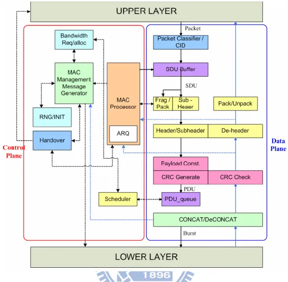
As shown in Figure 1-1, the MAC protocol layer, in terms of implementation, could be separated in two parts: the Data Plane and the Control Plane. The main function of the Data Plane is production of MAC layer’s protocol data units (PDUs). It could either be analyzed with electronic system level (ESL) methodologies, or realized by FPGA hardware solutions. The Control Plane takes charge of the Data Plane according to various signal feedbacks. These feedbacks include PHY-to-MAC, Network-to-MAC and inter-BS or BS-to-MS signaling.
Figure 1-1: MAC Layer Architecture
In recent years, in order to verify the functionality of MAC layer, major manufacturers begin to adopt MAC Emulators at early design stages to facilitate the accurate analysis, reduce design complexity and achieve better time-to-market. Considering the massive man power and time cost in designing a complete communication system, we think it is an ultimately important issue to take into account both the system performance and speedy system building. Based on this reason, our research puts emphasis on facilitating system verification speed, quick system prototyping, extensibility, and early detection of problems. All these factors contribute to a complete and quick system building.
Thus we introduce some new approaches to MAC prototype design. We apply Object-Oriented Analysis & Design (OOA&D) and hierarchical architecture principles in our
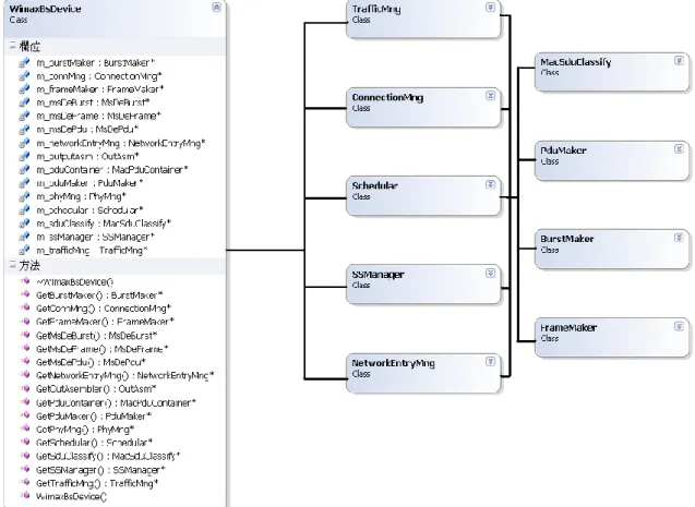
MAC design in order to facilitate functional analysis, bottom-up implementation and early-stage exhaustive verification. In the Future, without losing portability, we can port the original design to SystemC verification platform, which combines the object-oriented nature and cycle-accurate hardware simulation. The criteria of quick system prototyping and accurate verification are thus satisfied at the same time. A brief expression of hierarchical system architecture, in terms of OOA&D, is shown in Figure 1-2.
Chapter 2.
Mobile WiMAX System Review
WiMAX (Worldwide Interoperability for Microwave Access) is a telecommunication protocol that provides fixed and fully mobile internet access. The current WiMAX revision provides up to 40 Mbit/s with the IEEE 802.16m update expected offer up to 1 Gbit/s fixed speeds. The name "WiMAX" was created by the WiMAX Forum, which was formed in June 2001 to promote conformity and interoperability of the standard.
2.1.
WiMAX Network Topology
Figure 2-1 shows the WiMAX topology. The transmission supports LOS (Line-of-Sight) and NLOS (Non-Line-of-Sight). The topology is like GSM network. There are BSs and MSs and BSs can communicate with each other. But the different is that WiMAX backbone network is IP based core network.
2.2.
MAC Layer Technical Overview
A characteristic of WiMAX MAC layer is that it is connection-oriented. Each connection is distinguished with a 16-bit connection identifier (CID). When performing network entry, an MS sets up multiple connections with the BS. The connections are created based on the services mapped to the MS, including broadcast, management and data transmission services. Each data connection is associated to a QoS level. Connections are dynamically added or dropped if services are initiated or terminated with the MS.
The WiMAX MAC also uses a scheduling algorithm for which the subscriber station needs to compete only once for initial entry into the network. After network entry is allowed, the subscriber station is allocated an access slot by the base station. The time slot can enlarge and contract, but remains assigned to the subscriber station, which means that other subscribers cannot use it. In addition to being stable under overload and over-subscription, the scheduling algorithm can also be more bandwidth efficient. The scheduling algorithm also allows the base station to control quality of service (QoS) parameters by balancing the time-slot assignments among the application needs of the subscriber stations.
2.2.1. MAC PDU
MAC protocol data unit (PDU) is a data unit for protocol communication between the MAC layers of BS and MS. Basically, data traffic comes in the form of service data units (SDUs) from upper layers. The MAC layer tunnels upper layer traffics without knowledge of the payload content (shown in Figure 2-2).
Figure 2-2: SDU and PDU Diagram
According to Reference [1], two MAC header types are specified:
– Generic MAC Header: Used in MAC PDUs containing payload data. The generic MAC header indicates length, destination CID, encryption key and included subheader type of the PDU.
– Bandwidth Request Header: Used for requesting uplink bandwidth by MS.
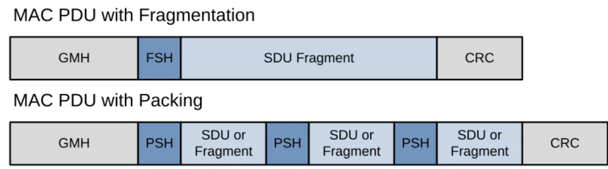
As Figure 2-2 shown above, the payload length is variable. Also, the SDU length from upper layer isn’t the fixed value. Because of those unpredictable reasons, there is a packing/fragmentation mechanism for the PDU payload. Each data fragment under packing/fragmentation should be attached to a packing/fragmentation sub-header.
Figure 2-3 shows examples of the ordering of data fragments and sub-headers.
GMH FSH SDU Fragment CRC GMH PSH SDU or Fragment PSH SDU or Fragment PSH SDU or Fragment CRC
MAC PDU with Fragmentation MAC PDU with Packing
2.2.2. MAC Frame Structure
WiMAX supports both time division duplex (TDD) and frequency division duplex (FDD) modes, but the OFDMA mode supports only TDD. For TDD mode, uplink and downlink use the same spectrum, and a PHY frame is separated into downlink and uplink subframe in time domain. A Typical frame structure layout is shown in Figure 2-4.
Figure 2-4: Typical TDD Frame Structure under OFDMA Mode [1]
1. Preamble:
Each downlink frame starts with a preamble, which lasts for one OFDMA symbol and occupies the entire spectrum. The preamble is robustly modulated in BPSK across subcarriers
2. Frame Control Header (FCH):
FCH contains Downlink Frame Prefix, which indicates the coding scheme and length of DL-MAP. MSs decode the DL-MAP according to information provided in FCH. The FCH uses the four logical subchannels following the preamble.
3. Downlink Map (DL-MAP):
The DL-MAP describes the DL subframe. By specifying subchannel and OFDMA symbol allocation to each user, the DL-MAP enables MSs to decode the DL subframe. Modulation of DL-MAP is fixed to QPSK, and the coding scheme is specified in the FCH. 4. Uplink Map (UL-MAP):
UL-MAP is similar to the DL-MAP. The UL-MAP describes the UL subframe, and namely bandwidth allocation among the served users. The UL-MAP is embedded in the first DL burst.
5. Downlink/Uplink Bursts:
DL/UL bursts contain data and messages to be transmitted by BS/MS. Each DL burst is mapped with a DL Interval Usage Code (DIUC), and the burst profile is provided in the DL-MAP. Similarly, each UL burst has a UL Interval Usage Code (UIUC), and its PHY characteristics are described in the UL-MAP.
6. Ranging Subchannels:
MSs use ranging subchannels to perform initial ranging, periodical ranging , handover ranging and bandwidth requests. Ranging is a process in which an MS adjusts its PHY parameters according to indicated by BS.
7. Transition Gaps:
Receiver mode and transmitter mode are separated by transition gaps to ensure proper operation. The gap from DL to UL subframe is Transmit Transition Gap (TTG), while the one from UL to DL is Receive Transition Gap (RTG).
Chapter 3.
The Implementation of MAC Emulator Platform
In this chapter, we introduce the proposed architecture including. First we try to explain the concept of hierarchical and modular design we proposed. Then, analyze the BS architecture (including data plane and control plane) by using these two concepts. Besides the BS, we also have a basic MS platform to negotiate with BS part. We try to put some significant elements in this emulator architecture, such as emulation scenario, timer, and multi-thread programming. Those significant elements will help the emulation more realistic.
3.1.
Hierarchical and Modular Design
In order to face the big emulator system, we are sure that we need a systematic way to analyze and maintain. We propose a hierarchical and modular design for the system. We convince there have some advantages as follows:
1. Systematic Analysis 2. Reusability
3. Reconfigurability
4. Extension to Advance use
These four advantages are explained in the following sections.
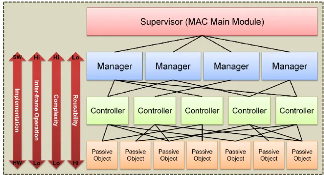
architecture includes four level classes: supervisor, manager, controller and passive object. These four levels imply some meanings such as reusability, complexity, inter-frame operation and implementation. The highest level is supervisor. The duty of supervisor is to control all the managers. For example, there are only one supervisor in the emulator called MAC main module. MAC main module (supervisor) controls manager modules and controller modules. Passive objects are driven by manager and controller modules.
Figure 3-1: Hierarchical MAC System Architecture Diagram
3.1.1.1.
Supervisor Module
There is only one supervisor module (MAC Maine Module) in whole emulator platform. The supervisor module controls all the behavior of the emulation such as handling the entry of MS, handling the interrupt situation, executing the emulation flow, and design of the FSM (finite state machine). We define the supervisor module is the highest level in the hierarchical architecture.
3.1.1.2.
Manager Modules
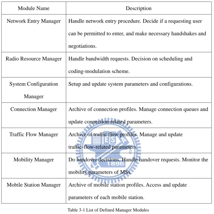
Manager modules are the second level below the supervisor module. The block diagram of manager modules is shown in Figure 3-2. They typically involve some joint decision and operation among multiple users, service flows, connections, and record profiles. Some manager modules serve as “archives” of various records. Any module in need can check the records in manager modules, but they can’t change records by themselves. They must send some information to the specific interface to inform manager modules and update the status. It’s also the characteristic of hierarchical architecture. Table 3-1 is listed some defined manager modules.
Module Name Description
Network Entry Manager Handle network entry procedure. Decide if a requesting user can be permitted to enter, and make necessary handshakes and negotiations.
Radio Resource Manager Handle bandwidth requests. Decision on scheduling and coding-modulation scheme.
System Configuration Manager
Setup and update system parameters and configurations.
Connection Manager Archive of connection profiles. Manage connection queues and update connection-related parameters.
Traffic Flow Manager Archive of traffic flow profiles. Manage and update traffic-flow-related parameters.
Mobility Manager Do handover decisions. Handle handover requests. Monitor the mobility parameters of MSs.
Mobile Station Manager Archive of mobile station profiles. Access and update parameters of each mobile station.
Table 3-1 List of Defined Manager Modules
3.1.1.3.
Controller Modules
Controller modules (shown in Fig 3-2) are the third level in the architecture. They just involve single user, traffic flow, connection, and record profile. Briefly speaking, these modules are much uncomplicated. They don’t need to handle multiple things. They only do
monotonous work. The main purpose is to perform routine logic and decisions. Table 3-2 is listed some defined controller modules.
Figure 3-3: Controller Module Block Diagram
Module Name Description Classification
Controller
Called by Data Plane Manager. Classify upper-layer packets into connections.
Ranging Controller Called by either Mobility Manager or Network Entry Manager. Handle single user’s ranging requests and make decisions on ranging messages and parameters. Performs either initial or periodic ranging.
Synchronization Controller
Called by Network Entry Manager. Obtain and maintain PHY and MAC synchronization.
ARQ Controller Called by Data Plane Manager. Produce and manage ARQ blocks. Framing Controller Called by Data Plane Manager. Produce/parse frames.
QoS Controller Called by Radio Resource Manager. Define and maintain the QoS of a single connection.
3.1.1.4.
Passive Objects
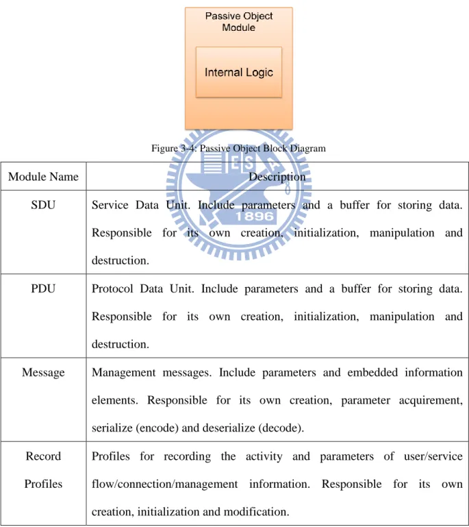
Passive objects (shown in Fig 3-4) are the basic level of whole MAC emulator architecture. As the name of this object, they are passive that means they don’t do anything actively. They wait for callings from other active modules, and they are self-supporting and independent. Table 3-3 is listed some defined passive objects.
Figure 3-4: Passive Object Block Diagram
Module Name Description
SDU Service Data Unit. Include parameters and a buffer for storing data. Responsible for its own creation, initialization, manipulation and destruction.
PDU Protocol Data Unit. Include parameters and a buffer for storing data. Responsible for its own creation, initialization, manipulation and destruction.
Message Management messages. Include parameters and embedded information elements. Responsible for its own creation, parameter acquirement, serialize (encode) and deserialize (decode).
Record Profiles
Profiles for recording the activity and parameters of user/service flow/connection/management information. Responsible for its own creation, initialization and modification.
3.1.2. Reusability and Reconfigurability
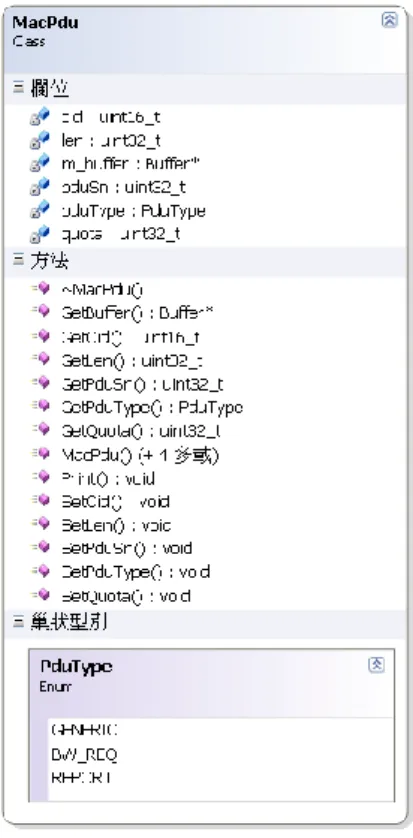
Besides the hierarchical design, we also apply Object-Oriented Analysis and Design (OOA&D) principle in this platform. In OOAD, there is an important characteristic called data encapsulation. While we want to design a module, all we need to think is what members the module should have and what functions the module should do. That is data encapsulation. For example, the class diagram of PDU is shown in Figure 3-5.
Figure 3-5: PDU Class Diagram
We put the members and functions in the class. That helps the design consideration and reusability. As for reusability, we can modify the existing class for other platform. Because of the flexibility, we don’t need to design a whole new module for other specific protocol. It reduces development time.
hierarchical design, we recommend that lower level modules can be reusable (controller and passive object). After the analysis of two different systems, it is sure that MAC should have some general parts and specific parts which illustrated in Figure 3-6. We can modulate the general part and build new modules for specific parts. Then, carefully design the negotiation bridge between two modes. The negotiation bridge will be the challenge of dual-mode design.
Figure 3-6: Reconfigure MAC Architecture
3.1.3. Extension to Advance Uses
Although the MAC emulator platform is a software approach, we can add hardware to become HW/SW co-design. Nowadays, ESL (electronic system level) become a popular verification way. It can combine hardware and software in one platform. As an example for the emulator, the basic routine part (ex: data plane) can be modified to Verilog (hardware description language) and control or decision part can be software approaches. That can make the emulator platform more realistic because of the addition of hardware.
Another one is using SDR (software-define radio) to make dual-mode device. More and more standards use same physical base (OFDM). Therefore, we can use SDR to implement dual-mode on one physical base. That can reduce chips costs and device area.
3.2.
BS MAC Emulator Architecture
Figure 4 shows the proposed BS architecture. The red part is control plane, and blue part is data plane. Data plane takes charge of the data formation from upper layer SDU to frame. Control plane sends some decision information and updates some states. We also have information from physical layer. This information will help the scheduling manager to do better decision.
Figure 3-7: Overall BS Architecture
given by the control plane, and executes the control plane’s commands by sending management messages to the air interface. Data plane includes the following components:
1. SDU Classification Controller:
SDU classification controller will classify the SDU by their CID to the respective connection queue as shown in figure 3-8. Also SDU classification controller will inform connection manager in control plane to update connection information (add connection or delete connection). All the SDUs will be stored in respective connection queue and wait for scheduling. START Is SDU queue empty? Y Classify SDU By CID N Inform connection manager to update status
Move SDU from SDU queue to connection queue Is SDU queue empty? N FINISH CLASSIFICATION Y
2. SDU Scheduling Controller:
SDU Scheduling Controller follows the signal from the Scheduling Manager in the control plane. Select the SDU from all connection queues and store them in the scheduled queue as shown in figure 3-9. Controller is only to do the selection work, and the scheduling algorithm part is in Scheduling Manager in control plane.
START
Scan all the existing connection queue Get information (num of SDU) from scheduling manager
Select SDU from relative connection
queue and put them to scheduled queue More traffic ? Y FINISH SCHEDULING N
Figure 3-9: SDU Scheduling Controller Flow Chart
3. PDU Maker Controller:
PDU is constructed by header and data (shown in Figure 2-2). PDU maker will check the scheduled queue every 5ms. While it’s not empty, PDU maker accesses the scheduled SDU. Estimate the data length and CID, and write information in the respective header. Then, combine header and data into PDU which will be stored in PDU queue.
PDU length is also decided in PDU maker controller. Because of the channel condition, PDU length is variable. We could send a big PDU while the channel condition was great. If the condition was bad, the PDU length could be shorter. So we have the mechanism for
START Append subheaders other than packing/ fragmentation subheaders Subtract subheader size from payload quota Is the SDU packing/frag allowed? Retrieve SDU from indicated CID Just-fit Logic N Y Compare residual
SDU size with payload quota (PAY – 2PSH) < SDU < (PAY – FSH) SDU > (PAY – FSH) SDU fragmented? Fragmentation Logic N Y Fragmentation subheader Next PDU SDU < (PAY – 2PSH) Packing Logic Packing
Subheader Payload quota left?
N Y
PSH: Packing subheader (2 bytes) FSH: Fragmentation subheader (3 bytes)
Figure 3-10: Packing/Fragmentation Logic Flow
4. Burst Controller:
Burst is concatenated by many PDU. There are lots of PDU with different CID in the PDU queue. Burst Controller checks all the PDUs in the queue and concatenates them into bursts respectively. In this emulator platform, we simplify the relation between user ID and CID. In the default situation, user ID and CID are the same value (1-1 mapping).
START Access first PDU in PUD queue and check its CID
Check CID from the next
PDU
Concatenate them Equal
Pop out the used PDU
Non-equal Is PDU queue empty? N FINISH Y
5. Framing Controller:
Figure 2-4 is the typical frame structure in IEEE 802.16 (WiMAX). In this emulator platform, we don’t consider the 2-D resource allocation (the emulator doesn’t support MCS and some physical effects). We design the frame structure as shown in figure 3-12. The information of bursts will be write (serialize) to DL-MAP, and MS will check the DL-MAP block to be sure which burst it wants.
Figure 3-12: Frame Structure under the Proposed Emulator Platform
START PreambleSerialize DL-MAPSerialize SerializeUL-MAP
Serialize burst
Pop out the used burst Is burst queue empty? FRAMING COMPLETE Y N
3.2.2. Control Plane
Control plane collects lots of information and makes decisions for data plane. Take Figure 3-14 as an example. Scheduling controller, PDU size controller and MCS controller will send the information to relative data plane manger. In this emulator platform, the trigger signal to control plane can be transmitted from lower layer (physical layer) or made by some assumptions. We use some channel models (such as shadowing and path loss) to create the information from physical layer. Without the control plane, data plane is just a frame generator. Carefully design the control plane can make the platform more flexible and smart.
Figure 3-14: Control Plane and Data Plane operation
We develop some control plane managers to enhance the emulator platform:
1. Network Entry Manager
While the MSs turn on or move into the coverage of BS, they will do network entry procedure. Figure 3-15 is described that BSs’ behavior. We also do these procedures to make
sure MSs’ logging in our platform. START PHY Synchronization MAC Synchronization Initial Ranging Basic Capability Negotiation Authorization And Key Exchange Registration FINISH PHY Preamble Sync. UL/DL Param. Accquired Ranging & Automatic Adjust Complete
Registration Complete
Figure 3-15: Network Entry Manager Flow Chart
2. Connection Manager
Connection Manager takes charge of managing all the service connection. For all of the situations, connection manager will update the status of the connections such as adding and deleting connection. We also classify connections into eight types: uninitialized, broadcast, initial ranging, basic, primary, transport connection, multicast and padding. Figure 3-16 gives a UML diagram that we define the connection manager module and WiMAX connections (passive objects). Because WiMAX is a connection-based system, connection manager must be carefully designed. The connection manager is like a information control center. We apply the STL (Standard Template Library) containers (such as vector, queue, deque…etc) to store the connection information and SDUs from upper layer. We can easily store, access, and
Figure 3-16: Connection Manager UML Diagram
3. Scheduling Manager
Scheduling Manager provides the architecture that schedule algorithm and interface are separate. We can easily add new algorithm and choose different algorithm to check the performance. Because we don’t have the physical model for modulation coding scheme, we use the quantities of PDU for scheduling principle. If the radio resource is enough, we can select more PDUs for the respective users.
Figure 3-17: Scheduler Architecture
3.3.
Basic MS MAC Emulator Architecture
MS (mobile station) is the receiver part in the emulator platform. It has basic decode functions (decode frame, decode bursts, decode PDUs). The received frame includes all of the MSs’ bursts, so we need to read the DL-MAP. DL-MAP stores the information of the respective downlink bursts. We use CIDs to map users (1-1 mapping). After MS deserialize the information of the burst location, MS takes the respective burst and puts in burst queue. Other useless bursts and information will be released to save memory block. A Burst is constructed by many PDUs. MS calculates the quantities of the PDUs (burst size divided by PDU size) and decodes them to PDUs. All the decoded PDUs are stored in the PDU queue, and MS decomposes the PDUs into the original SDUs. These SDUs should be streaming datagrams or fragments from some indicated pre-stored files (picture). As for streaming, we open the UDP socket and indicate the local address and port (shown in Figure 3-26).
STRAT Network Entry Procedure Receive Frame?
Decode Frame (deserialize DL-MAP
which indicates the respective parts) Decode Burst (deserialize header) Decode PDUs (deserialize header) Original SDU is put in the SDU
queue
Y
FINISH
.
Figure 3-26: Streaming for MS
Application of streaming has an obvious advantage. The emulator not only performs monotonous data transferring. We can use real traffic and emulate the effect of traffic loading. If the resource of emulator (it means the ability of emulator computation) is congested with the traffic jams (lots of resource request), the scheduling manager will arrange the resource depends on the QoS. The scheduled result will be shown on the monitor by VLC player. VLC player can decode the movie with receiving lots of datagram in a period time. The quantities of datagram are variable because of the codec (mpeg4, H.264…etc). But we can still use the decoded result which is successful or not as scheduled consequence. Briefly speaking, we can verify the specific scheduling algorithm by watching the streaming on the monitor which is played fluently or not.
3.4.
Connection Interface between BS & MS
Most of the emulators put the BS and MS in one project, but our platform is different. We make MS and BS as two divided and independent modules. The difference is that two independent modules doesn’t share the same memory block. It is much more like real BS and MS. In the real case, BS and MS use wireless module (RF chips) to connect each other. But in our emulator platform, we focus on the MAC operation instead of physical layer effects. So we use wire connection instead of wireless connection.
3.4.1. Socket Programming
We use windows socket programming to connect BS and MS. Socket programming gives us a convenient interface to drive the layers below transport layer. Figure 3-18 gives us a clear concept. We put our process (emulator platform) on the socket interface, and use the existing API by socket library. We can easily drive the network protocols to make a wire connection.
3.4.2. TCP and UDP socket programming
We can make TCP and UDP connection by using socket programming. In this section, we just describe the implementation of TCP and UDP connections instead of protocol parts. TCP is connection-oriented. We can see Figure 3-19 that shows a TCP socket flow. In this flow, we can see the server continuous listening and waiting for the response to ensure the reliable connection.
Figure 3-19: TCP Socket Program Flow
UDP connections are much simpler. UDP connections just need to bind the address and continuous sending packet to the indicated address. UDP connection doesn’t care about the reliability. The application of UDP is streaming. YouTube provides streaming platform on the internet. The streaming server like YouTube just sends the datagram (UDP packet) to the request address. If some datagram is missing, server won’t retransmit the missing part. For terminals, maybe just miss a short period of the streaming. Figure 3-20 shows a UDP socket program flow.
Figure 3-20: UDP Socket Program Flow
3.4.3. Sockets Application on Emulator Platform
The characteristics of TCP and UDP are quite different. TCP has a reliable connection. We can use it in transferring some acknowledgement message. For example, the network entry procedure needs some acknowledgement message to change the state (network entry FSM). As for UDP, in our platform we use it in streaming.
Figure 3-21 gives an illustration about the network architecture of platform. VLC is an open-source media player which supports streaming sending and receiving. In one version of our platform, we can use a VLC player as a streaming server which continuously sends the datagrams. All the sending datagrams will be received by the indicated BS module. After the
the VLC player. We can use the player watching streaming on MS sides.
3.5.
Emulated Scenario and Physical Information
Figure 3-22 shows a 2-tier cellular architecture. Each cell’s coverage is the relative BS’s coverage. We set the reuse factor which equals 1, that means all the cells use the same frequency. Because of this scenario, we can calculate the SINR (signal to interference plus noise ratio)
Figure 3-22: Emulated Scenario
Equation (3.1) is the calculation of SINR. According to EVM (evaluation methodology), we add the shadowing and path-loss effect to calculate the signal and interference. Equation (3.2) lists the elements of the signal and interference. is the transmission power, and it’s set as the fixed value which is -47dBm. is the antenna gain, and it’s set as the fixed value which is 17dBi. and S is the effect of path-loss and shadowing. The calculation
will calculate the SINR according to MS’s location. If the MS is fixed point, BS just only calculates once. If the MS is mobile point, BS calculates the SINR every 5ms (frame time). After the calculation of the SINR, the scheduling manager uses the MAX-CINR to allocate the resource to MSs. Bigger the SINR is, more SDUs can be selected.
(3.1)
(3.2)
Transmission power is related to the location of MSs, and antenna gain is related to the direction of the antenna. It is much more complicated. In our platform, we want to simplify the situation, so we fixed the value of and . Although the and is fixed, we have the flexible architecture to add some physical model if needed.
3.6.
Multi-Thread for Realistic BS Operation
When a program is loaded into memory, it is called a process. But one process a have multiple threads. A thread of execution is the smallest unit of processing that can be scheduled by an operating system. The sequential execution is that a process only have one thread, and this thread do all of the process sequentially. For multi-thread, there are multiple threads in one process, and those threads can execute the process independently. Multi-thread programming also can be used for parallel process. Later we will introduce the application of parallel processing in our emulator platform.
The sequential execution isn’t suitable for the MAC emulator. In the real BS, all the process is parallel. We have developed and improved the MAC emulator. We can see the Figure 3-23 which illustrates the sequence of the older version emulator platform. The emulator always receives the packet from the streaming server, and then it does some frame works (packing to PDU). After the basic BS operation, emulator sends them to the MSs.
Actually the BS operation is not normal for sequential process. We notice that the input of the emulator can’t only have one streaming. There should be multiple streamings sent by many streaming servers. The existing emulator platform can’t handle those parallel streaming input. So we revised the emulator platform. Our new feature is handling multiple streaming parallel by using multi-thread. We set many threads (the number of threads depending on the number of inputs) to handle the coming streaming. Figure 3-24 illustrates the multi-thread processing. Take Figure 3-24 as an example, there are three inputs: FTP transferring (from pre-stored files), streaming 1 and streaming 2 (from two different streaming servers). These
a frame in every 5ms. We collect all the SDU from the time period, and use these collected SDUs to do frame work. After the frame work, the BS sends them to the indicated MSs. The thread of frame work and the threads of input are independent. It assembles to the real BS operation.
Figure 3-23: Sequential Execution of the Platform
Chapter 4.
Demo Case of Emulator Platform
We want to perform a demo for our emulator platform. In this chapter, these three devices (streaming server, BS, and MS) are in the same computer because it is simpler to show the response of each device. It can be run in three different computers as shown in Figure 3-21. The situation is that BS has a streaming input which is sent by streaming server (in real world, it’s like YouTube.). Besides the streaming input, we create congestion inside the BS. Because of the congestion, the streaming which is shown on the MS side has the probability that MS can’t decode it. Because congestion shares the resource of BS, MS can’t receive amounts of datagram to decode the stream. Figure 4-2 shows that the MS can’t decode the movie completely. Because of that, we use the schedule manager to raise the level of QoS. The schedule manager decreases the quantities of SDUs which is selected to make PDUs. Also, raise the priority of the streaming service. Figure 4-3 shows the scheduled result. We can play the streaming fluently.
Base Station
Figure 4-2: Screen Shot (streaming priority low)
Figure 4-3: Screen Shot (streaming priority high)
MS Decode Failed
Chapter 5.
Conclusion and Future Works
In the article, we propose a hierarchical and modular methodology in the design of generic MAC emulator platform, and give an implementation of WiMAX MAC emulator with the proposed methodology. We clearly defined the MAC architecture by using hierarchical and modular design. We don’t focus on the improvement of transmission throughput or effective algorithm. Our contribution is to give a well-defined emulator platform. All the components are modular and hierarchical, and the architecture is flexible. It is possible to add more modules in the future. The applications of the emulator platform are various, such as HW/SW co-design, ESL verification, and embedded system design. The purpose for this emulator is that reduces the time for development and increase the accuracy of the verification.
The wireless environment (RF) is replaced to wired environment (internet). Many embedded system has its own RF module. In the future, we can port our MAC system to the embedded system. It is possible for the transplantation. Windows sockets part can be change to linux sockets, and multi-thread parts can be change to POSIX thread library. We only need to drive the RF module for physical transmission. The architecture doesn’t change for the transplantation. It can solve the problem that uses wired transmission in wireless protocol implementation.
Emulator isn’t like simulator. Emulator is a bit by bit operation platform. To a certain extent, it has the much more real response to the activity by applying some new features. For example, we illustrate the scheduling algorithm performed in Chapter 4. The physical model
two-dimension (OFDMA symbol and subchannel). The effective two-dimensional allocation is also an important research that can be verified with MCS-support MAC emulator platform.
The mechanism of FSM (finite state machine) is also important. Both MS and BS need a complete FSM for any interrupt situation. FSM plays an important role in the MAC design. It is not only one MS in the BS. Handling many MSs needs a complete FSM to control. Another work is using the reconfigurbility to make multi-system. Many protocols use the same physical base. We can combine two different protocols (like WiMAX and Wifi even LTE) in one system and device by modified the software which is called SDR (software defined radio) I mentioned in section 3.1.2.
In summary, physical model, complete FSM and multi-system issues are three important works in the future. These three issues can lead the MAC emulator much more realistic and effective.
Reference
[ 1 ] IEEE 802.16 Working Group, “IEEE Standard for Local and Metropolitan Area Networks – Part 16: Air Interface for Fixed Broadband Wireless Access Systems,” IEEE Std. 802.16-2004, October 2004.
[2] GuoSong Chu, Deng Wang, and Shunliang Mei, “A QoS Architecture for the MAC Protocol of IEEE 802.16 BWA System,” on Communications, Circuits and Systems and West Sino Expositions, IEEE 2002 International Conference, vol.1, pp. 435-439, 2002. [3] De La Oliva A, Banchs A, Soto I, Melia T, and Vidal A, “An Overview of IEEE
802.21:Media-Independent Handover Services,” IEEE Wireless Communications, vol.15, pp. 96-103, August 2008.
[4] Rehan Qureshi, Arek Dadej,and Qiang Fu, “Issues in 802.21 Mobile Node Controlled Handovers,” Telecommunication Networks and Applications Conference, pp. 53-57, 2007.
[5] Hans-Peter Loeb, Christian Lis, and Christian Sauer, “UMAC – A Universal MAC Architecture for Heterogeneous Home Networks,” Digital Object Identifier, 2009. [6] 涂治安譯,精通 Windows Sockets 網路程式設計,碁峰資訊股份有限公司,民 98
年

![Figure 2-4: Typical TDD Frame Structure under OFDMA Mode [1]](https://thumb-ap.123doks.com/thumbv2/9libinfo/8751070.205937/18.892.146.804.416.806/figure-typical-tdd-frame-structure-under-ofdma-mode.webp)