國
立
交
通
大
學
資訊工程學系
博
士
論
文
行 動 網 路 內 安 全 多 路 徑 連 結 架 構 之 設 計
The Design of Secure Multi-Homed Architecture in Mobile Networks
研 究 生:羅嘉寧
指導教授:謝續平 博士
行動網路內安全多路徑連結架構之設計
The Design of Secure Multi-Homed Architecture in Mobile Networks
研 究 生:羅嘉寧 Student:Jia-Ning Luo
指導教授:謝續平 博士 Advisor:Dr. Shiuhpyng Shieh
國 立 交 通 大 學
資 訊 工 程 學 系
博 士 論 文
A Dissertation
Submitted to Department of Computer Science and Information Engineering College of Electrical Engineering and Computer Science
National Chiao Tung University in partial Fulfillment of the Requirements
for the Degree of Doctor of Philosophy
in
Computer Science and Information Engineering
July 2005
Hsinchu, Taiwan, Republic of China
行
動
網
路
內
安
全
多
路
徑
連
結
架
構
之
設
計
學生:羅嘉寧
指導教授:謝續平 博士
國立交通大學資訊工程學系
摘
要
隨著行動通訊的發展與普及,現今的行動裝置常具有兩種以上的網路介面,稱之為多路徑連結 架構網路。在一個多路徑連結架構網路中,行動裝置可以根據不同的應用與需求,即時選擇一 個最佳的網路介面,如此可以承受多種網路障礙,網路延遲或封包遺失之情形,進而提升整體 網路的傳輸品質。然而,設計一個完善的多路徑連結網路需要多方面的考量,因此本論文將探 討以下三項主題: 本論文所要探討的第一個主題是網際網路的擴充問題。在現今的網路架構中,最常用來解 決網際網路擴充問題的方式是使用網際網路位址轉譯器 (NAT)。然而網際網路位址轉譯器有許 多的缺失,例如無法連結至多階層私有網路中,以及可能存在網際網路位址衝突的問題。因此 我們提出了一種解決方案,稱之為 MRSIP 架構,以取代網際網路位址轉譯器。使用 MRSIP 架 構將使得在 NAT 架構下的前述問題加以解決。 本論文的第二部份著眼於改進一個在多連結路徑網路下所使用的通訊協定,稱之為資料流 控制傳輸協定 (Stream Control Transmission Protocol; SCTP)。然而因為原先資料流控制 傳輸協定並不是針對多連結路徑網路而設計,因此我們探討使用該傳輸協定的不足,如路徑選 擇及網路轉換效率問題等,並針對這些問題提出一系列的解決方案及加以分析。.
在本論文的第三部分中,我們提出了一個新的身份確認及金匙交換協定,以用於多連結路 徑網路。在這個協定裡,並不需要有一個公正的第三者以作為金匙交換的中介者,如此可以避 免因網路傳輸中斷導致無法進行身份確認的情形。在這個身份確認及金匙交換協定中,我們解
決了以前學者發現的問題並加以改良,而且只需從事較少的指數運算及記憶體,因此非常適用 於只具備些許運算能力及記憶體的行動裝置中。
The Design of Secure Multi-Homed Architecture
in Mobile Networks
Student:Jia-Ning Luo
Advisors:Dr. Shiuhpyng Shieh
Department of Computer Science and Information Engineering
National Chiao Tung University
ABSTRACT
With the growth of mobile computing, currently a mobile device may have one or more network interfaces, which is called as ‘multi-homed network.’ In a multi-homed network the data connections can be placed in the best possible interface or forwarded through several paths thereby decreasing end-to-end delivery delay and increasing the network capacity. Also, using a multi-homed network can improve the network performance because it is against network failure or network partitioning. To address these situations, this thesis investigates solutions in multi-homed architecture in mobile networks. Research consists three parts:
Part one investigates the solution of Internet scaling problem. The well-known solution of Internet scaling problem is using the Network Address Translator (NAT). However, there are still many problems cannot be solved by NAT. For example, NAT cannot access to multi-level private network, or prevent the address collision. To overcome these problems, we propose the MRSIP framework to replace the NAT.
Part two investigates the enhancement of communication protocol to be used in multi-homed network architecture, the Stream Control Transmission Protocol (SCTP). Since the original
designing of SCTP protocol is not to be used in multi-homed network, we discuss the drawback of SCTP protocol such as path selection and changeover decision problems, and propose several algorithms to solve these problems in the SCTP protocol.
In part three, we propose a new authenticated key agreement protocol to be used in the multi-homed network environment. In the propose protocol, the key information center is needed only when the secure network system is being set up or when new users request to register. Furthermore, our protocol needs fewer exponential computations and memory, which is suitable for the low-end mobile devices. Finally, we discuss the possible extensions and conclude.
Acknowledgement
I am grateful to my advisor Shiuhpyng Shieh for his advices and patience over these years. Special thanks are also to the other readers of this work including L. M. Tseng, W.B. Lee, R. J. Hwang, J.H. Chiu, R. J. Chen, and S. K. Hwang. Their valuable comments and suggestions have helped make this thesis much better.
I also thank for all the classmates, seniors and juniors in the distributed system and network security lab, especially C. T. Lin, C. H. Wu and S. I. Hwang. Without their support, I cannot finish this thesis smoothly.
Finally, I dedicate this thesis to my family, and my girlfriend Y. T. Yang, for their understanding and support.
Contents
Table of Contents i
List of Figures iii
List of Tables v
1 Introduction 1
2 Related Work 4
2.1 Network address translation (NAT) and it’s variants . . . 5
2.1.1 NAT variants . . . 6
2.1.2 Application level gateway . . . 10
2.1.3 NAT limitations . . . 11
2.1.4 Realm-specific IP . . . 12
2.1.5 Problems with RSIP . . . 15
2.2 Multi-Homed networks . . . 16
2.2.1 Mobile IP and mobile IPv6 . . . 20
2.2.2 SCTP protocol . . . 21
2.3 Authentication protocols to be used in multi-homed networks . . . 24
2.4 Summary . . . 26
3 Multi-Layer RSIP Management Architecture 28 3.1 System components and terminology . . . 29
3.1.1 Registration of MRSIP clients . . . 31
3.1.2 De-registration of MRSIP clients . . . 32
3.1.3 Address binding . . . 32
3.1.4 Address unbinding . . . 34
3.1.5 Address collision avoidance . . . 35
3.1.6 Security aspects . . . 37
3.2 Protocol specification . . . 38
3.2.1 Parameter specification and formats . . . 38
3.2.2 Control message types . . . 40
3.3 Two protocol examples . . . 43
3.4 Comparison . . . 47
3.5 Summary . . . 48
4 Multi-homed Architecture in Mobile Networks 50 4.1 Problems in SCTP protocol . . . 51
4.1.1 Path-selection and multi-homing . . . 52
4.1.2 SCTP failover control . . . 54
4.2 Proposed enhanced SCTP protocol . . . 57
4.2.1 Primary path selection algorithm . . . 58
4.2.2 Alternative path selection algorithm . . . 59
4.2.4 Long-term failover algorithm . . . 62
4.3 Performance evaluation . . . 63
4.3.1 Two paths with same network speed between endpoints . . 64
4.3.2 Three paths with different network speed between endpoints 66 4.4 Summary . . . 68
5 Secure Communication in Multi-homed Networks 72 5.1 Multi-homed networks and peer-to-peer applications . . . 73
5.2 Proposed secure authenticated key agreement protocol . . . 75
5.3 Computation overhead . . . 83 5.4 Security analysis . . . 84 5.5 Summary . . . 87 6 Conclusion 89 Curriculum Vitae 100 Publication List 101
List of Figures
2.1 Network Address Translation Framework . . . 6
2.2 Application Level Gateway (ALG) . . . 11
2.3 Example Network of RSIP architecture . . . 13
2.4 Cascaded RSIP Network . . . 15
2.5 Redundant link in RSIP . . . 17
2.6 Multi-homed Network with NAT, case 1 . . . 18
2.7 Multi-homed Network with NAT, case 2 . . . 19
2.8 Multi-homed Network with NAT, case 3 . . . 20
3.1 Address binding in MRSIP framework . . . 35
3.2 The address collision of two private networks (I) . . . 36
3.3 The address collision of two private networks (II) caption . . . 37
3.4 Client communicates with host resides in public network . . . 44
3.5 Client communicates with hosts resides in another private network 47 4.1 SCTP retransmit state diagram with congestion . . . 55
4.2 SCTP retransmit state diagram with failure . . . 56
4.3 Two paths with same network speed between endpoints . . . 65
4.5 Two paths, link 0 down for 30 seconds . . . 66 4.6 Two paths, link 0 down for 45 seconds . . . 67 4.7 Two paths, link 0 down for 90 seconds . . . 67 4.8 Three paths with different network speed between endpoints . . . 68 4.9 Three paths, link 0 and link 1 down for 15 seconds alternatively . 69 4.10 Three paths, link 0 and link 1 down for 30 seconds alternatively . 69 4.11 Three paths, link 0 and link 1 down for 45 seconds alternatively . 70 4.12 Three paths, link 0 and link 1 down for 90 seconds alternatively . 70 5.1 Message flow in the initial phase . . . 77 5.2 The authenticated key agreement phase . . . 80 5.3 The subsequent authentication phase . . . 82
List of Tables
2.1 Address Mapping of Static NAT . . . 7
2.2 Address Mapping of Dynamic NAT . . . 8
2.3 Address Mapping of NAPT . . . 8
3.1 Comparison of NAT, RSIP and MRSIP . . . 48
4.1 Terminology . . . 52
Chapter 1
Introduction
In the current Internet environment, enterprises often use private address space to setup their network environment for a variety of reasons. Three major rea-sons that use private network are firewall, Virtual Private Network (VPN) and Network Address Translator (NAT). By having more address space, this enables operationally and administratively convenient addressing schemes as well as eas-ier growth paths. For example, companies run firewall systems may use private address space to isolate internal networks. People also use NAT to build home networks when they cannot get enough IP addresses from their Internet Service Provider (ISP).
The hosts that reside in a private network are unreachable by the Internet routers by default because Internet routers will not route packets that come from private network addresses. NAT is proposed to solve half of this problem. How-ever, Internet users may wish to communicate with those unreachable hosts, espe-cially when they use peer-to-peer applications such as Internet-Telephony, MSN, Internet game, file sharing or terminal service.
The cascade private network occurred when users in a private network build another private network inside. For example, assume one big company built a private network to reduce the amount of public IP addresses. The research depart-ment in this company may wish to build a small private network to protect their sensitive data. Assume these two private networks are interconnected by a NAT device. To allocate the resources inside the private networks and to connect with them becomes an important issue.
Furthermore, In the quest for network redundancy, enterprises often subscribe more than one leased line from several network service providers to build a multi-homed network environment. In a multi-homing network the data connections can be placed in the best possible interface or forwarded through several paths thereby decreasing end-to-end delivery delay and increasing the network capacity.
Another aspect of performance improvement due to multi-homing is against network failure or network partitioning. To address these situations, this thesis investigates solutions in multi-homed architecture in mobile networks.
This dissertation is organized as follows:
Chapter 2 briefly introduce the related work of Internet scaling problems and multi-homed network architecture, includes the Network Address Translation (NAT) and it’s variants, the multi-homing protocol such as Stream Control Transport Protocol (SCTP), and the authentication protocols to be used in the multi-homed networks.
Chapter 3 investigates the MRSIP architecture that to be used in communi-cating . The basic design objectives of MRSIP can be summarized as follows: transparent-access capabilities with the private network, cascade private network architecture, redundant path reducing between source and destination nodes, and
reduce the address-collision probability.
Chapter 4 discuss the problems exists in the SCTP, including the path selec-tion problem and failover problem. We proposed four algorithms to enhance the weakness of the original SCTP protocol.
In chapter 5, we propose a new authenticated key agreement protocol to be used in the multi-homed network. In the propose protocol, the key information center is needed only when the secure network system is being set up or when new users request to register. A new subsequent authentication phase is used to reduce the computation overhead and network traffic. Finally, we discuss the possible extensions and conclude.
Chapter 2
Related Work
In the quest for network redundancy, enterprises often subscribe more than one leased line from several network service providers to build a multi-homing net-work environment.
In a multi-homed network, the data connections can be placed in the best pos-sible interface or forwarded through several paths thereby decreasing end-to-end delivery delay and increasing the network capacity. Another aspect of perfor-mance improvement due to multi-homing is against network failure or network partitioning.
The most recently popular multi-homed environment is the mobile networks. Current mobile devices are often equipped with several network interfaces such as WLAN, GPRS, IrDA, or Bluetooth. During the communication period, the mobile device is able to migrate from one associated network behind an interface to the other.
In this chapter, we briefly introduce three major problems impacting the inter-net: the Network Address Translation (NAT), the multi-homing protocol such as
Stream Control Transport Protocol (SCTP), and the authentication protocols to be used in the multi-homed networks.
2.1
Network address translation (NAT) and it’s
vari-ants
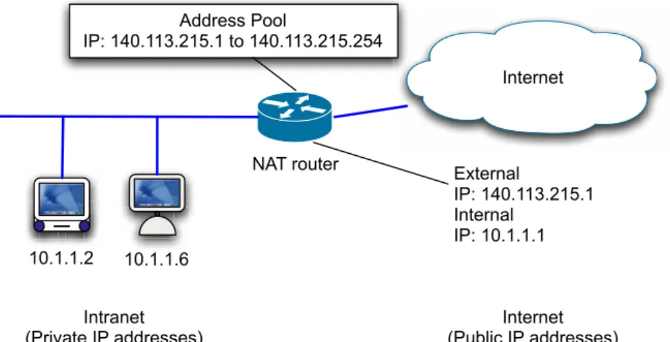
Network Address Translation is a method by which IP addresses are mapped from one realm to another, in an attempt to provide transparent routing to hosts [54]. NAT has been widely applied in network equipment due to the leakage of IPv4 addresses space. NAT’s fundamental role is to alter the addresses in the IP header of a packet [56]. Many applications cannot work under NAT environment because NAT servers try to modify the IP headers to provide transparent routings. These applications include well-known FTP and H.323 protocols [14]. To solve this problem, application-level gateway (ALG) is used [65]. Application-level gate-way works fine with common protocols such as FTP, SNMP and VoIP, but does not provide end-to-end security such as Kerberos, RPC, and IPsec [19, 52, 4, 40, 30]. Network Address Translation (NAT, as shown in Figure 2.1) has become a common Internet technology for a variety of reasons. In figure 2.1, an NAT router with two interfaces, 10.1.1.1 and 140.113.215.1, provides transparent routing be-tween two address realms, the Intranet realm (using private IP addresses) and the Internet realm (public IP addresses). NAT converts the inside addressing realm (e.g., 10.1.1.2) into another address realm (e.g., 140.113.215.2) before forwarding packets to public networks. In other words, NAT can be used to connect a private network, which uses unregistered private IP addresses with a public network that
uses limited registered IP addresses. Internet External IP: 140.113.215.1 Internal IP: 10.1.1.1 Internet (Public IP addresses) Intranet (Private IP addresses) Address Pool IP: 140.113.215.1 to 140.113.215.254 NAT router 10.1.1.2 10.1.1.6
Figure 2.1: Network Address Translation Framework
NAT allows hosts within a private network to uni-directionally access remote hosts in the external network. The IP addresses of the hosts in the private network are only unique within the network and may not be valid in the external network.
Traditionally, NAT is used to bind many private IP addresses and TCP/UDP ports into one globally unique IP address and its TCP/UDP port. Such kind of NAT methods allow hosts within a private network to transparently access hosts in the external network.
2.1.1
NAT variants
There are many variations of address translation that lend themselves to different applications: static NAT, dynamic NAT, network address port translation (NAPT), bi-directional NAT and twice NAT.
• Static NAT
addresses of hosts in a private domain as they originate sessions to the ex-ternal domain. For packets outbound from the private network, the source IP address and related fields such as IP, TCP, UDP, and ICMP header check-sums are translated. For inbound packets, the destination IP address and the checksums as listed above are translated.
In static NAT, the computer with the IP address of 10.1.1.2 will always translate to 140.113.215.2, as shown in table 2.1.
Source IP Address Destination IP Address 10.1.1.2 140.113.215.2 10.1.1.3 140.113.215.3 10.1.1.6 140.113.215.6 Table 2.1: Address Mapping of Static NAT
• Dynamic NAT
With dynamic NAT, all the available public IP addresses are stored in one address pool. NAT boxes will create (or update) an address mapping only when a session is established.
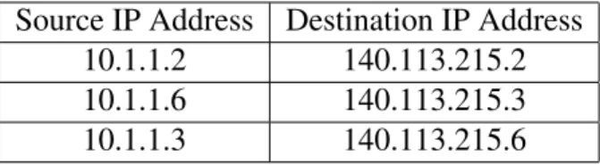
In dynamic NAT, it also establishes a one-to-one mapping between private and public IP address, but the mapping could vary depending on the public IP address available in the pool. For example, the computer with the IP ad-dress of 10.1.1.2 will translate to the first available adad-dress in the range from 140.113.215.2 to 140.113.215.254, which is 140.113.215.2. Later the com-puter with the IP address of 10.1.1.6 will translate to the second available address, 140.113.215.3, as shown in table 2.2
• Network Address Port Translation (NAPT)
translat-Source IP Address Destination IP Address 10.1.1.2 140.113.215.2 10.1.1.6 140.113.215.3 10.1.1.3 140.113.215.6 Table 2.2: Address Mapping of Dynamic NAT
ing transport identifier (for example, the TCP and UDP port numbers, or ICMP’s query identifiers). This allows the transport identifiers of a number of private hosts to be multiplexed into the transport identifiers of a single external address. That is, NAPT allows a set of hosts to share a single ex-ternal address. NAPT can be combined with traditional NAT so that a pool of external addresses are used in conjunction with port translation.
For packets outbound from the private network, NAPT would translate the source IP address, source transport identifier and related fields such as IP, TCP, UDP and ICMP header checksums. Transport identifier an be one of TCP/UDP port or ICMP query ID. For inbound packets, the destination IP address, destination transport identifier and the IP and transport header checksums are translated.
In table 2.3, the TCP packet from 10.1.1.2 with port 80 will be translate to 140.113.215.2 with port 80, and the TCP packet from 10.1.1.6 with port 80 will be translate to the same IP address 140.113.215.2 but the port number is different.
Source IP Address:Port Destination IP Address:Port 10.1.1.2:80 140.113.215.2:80 10.1.1.6:80 140.113.215.2:81 10.1.1.3:80 140.113.215.2:82
• Bi-directional NAT or Two-Way NAT
By using traditional NAT, hosts in an external network are not able to initiate a session request to a host inside the private network. This is in contrast with anther kind of NAT, Bi-directional NAT (see RFC 2663) [56] (also known as Two-way NAT).
A bi-directional NAT server allows sessions in both inbound and outbound directions. When the connection is established in either direction, the pri-vate network address is statically or dynamically mapped to a globally unique address. The assumption of bi-directional NAT is that Fully Qualified Do-main Names (FQDN) of hosts both in private networks and public net-works are end-to-end unique. Therefore, a DNS Application Level Gate-way (DNS-ALG) [57] is used with bi-directional NAT to facilitate name to IP address and TCP/UDP port mapping.
• Twice NAT
Twice NAT is a variation of NAT in that both the source and destination IP addresses are translated by NAT box. This is in contrast to Traditional-NAT and Bi-Directional NAT, where only one of the addresses (either source or destination) is translated.
Twice NAT is necessary when private and external realms have address col-lisions. The most common case where this would happen is when a site may have changed from one provider to another, but chosen to keep the addresses it had been assigned by the first provider. In such cases is that the address of the host in the external realm may have been assigned the
same address as a host within the local site. If that address were to appear in a packet, it would be forwarded to the internal node rather than through the NAT device to the external realm. Twice-NAT attempts to bridge these realms by translating both source and destination address of an IP packet, as the packet transitions realms.
2.1.2
Application level gateway
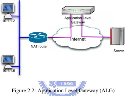
Despite the convenience brought by NAT, there are still some limitations and se-curity issues when NAT is applied. Not all applications are able to pass through NAT server transparently; especially those that carry IP address and TCP/UDP port information inside their payloads. In such applications, an Application Level Gateway (ALG, as shown in Figure 2.2) [56] is required to perform address trans-lations on application packets that contain IP address and TCP/UDP port infor-mation for outbound sessions. In Figure 2, all payloads routed by the NAT server will be forwarded to the ALG. The ALG interprets the payloads and performs the necessary address translations on the payloads of the connection. However, ALG is not intended for inbound connections. If a session is initiated from the public network, ALG cannot break through the NAT server, either. If inbound sessions must be allowed, ALG must be integrated with the NAT server. For some simple protocols that use fixed ports only, NAT with port forwarding [63] can be performed on the NAT server. Port forwarding function on the NAT server can forwards all packets from certain ports to their dedicated servers. In this case, we can also treat the NAT server as a virtual server that distributes the traffic among designated server farms.
The combination of NAT server and an ALG cannot provide end-to-end se-curity; especially when the NAT server and the application level gateway are not located in a trusted boundary. Furthermore, an ALG may become a bottleneck and forwarding throughput of the border router combined with the NAT server could be degraded considerably. Internet Application Level Gateway Server NAT router 10.1.1.2 10.1.1.6
Figure 2.2: Application Level Gateway (ALG)
2.1.3
NAT limitations
There are some other limitations when using NAT to handle translations between private addresses and a small range of addresses that were allocated for public use. For example, since a NAT router keeps the mapping relations of all sessions established through it, the requests and responses of those sessions must be routed via the same NAT router. For this reason, it is usually recommended to combine a NAT router with a border router in a domain. However, such configuration makes an NAT router the target of attacks and intrusions.
No matter what kind of NAT method is used, the TCP/IP checksums in the for-warded packets cannot be encrypted since NAT requires the capability to translate any part of the headers and packets according to the referred addressing scheme. If data encrypted within an IP packet contains information that must be translated, it becomes extremely difficult for a NAT server to perform any network address translation. Thus, any host applying encryption to TCP/IP checksums should be assigned a globally unique IP address, exempted from NAT.
In addition, NAT may potentially break the end-to-end nature of applications on the Internet; therefore, the use of NAT threatens the end-to-end security of the Internet. Actually, many security protocols exchange IP addresses or TCP/UDP port related information in their authentication packets. These security protocols are vulnerable to disability for passing through the NAT server. As a result, a certain group of security protocols may fail when applying such addresses trans-lations to their authentication packets.
2.1.4
Realm-specific IP
Realm-Specific IP (RSIP) is another approach that based on the concept of grant-ing a host from one addressgrant-ing realm a presence in another addressgrant-ing realm by allowing it to use IP address from the second addressing realm [3]. An RSIP server/gateway replaces the NAT box, and RSIP-aware hosts on the private net-work are referred to as RSIP clients. RSIP clients inside a private can lease a public IP address to communicate with outside hosts. The RSIP protocol is ex-tended to support both IKE (a UDP application) and the IPsec-defined AH and ESP headers [39, 28, 29, 12].
Due to the limitation of NAT mechanism, Realm Specific IP (RSIP) provides an alternative solution. RSIP is based on the concept of granting a host from one address-ing realm a presence in another addressing realm by allowing it to use IP addresses from the second addressing realm. An RSIP server replaces the NAT router, and RSIP-enabled hosts are referred to as RSIP clients.
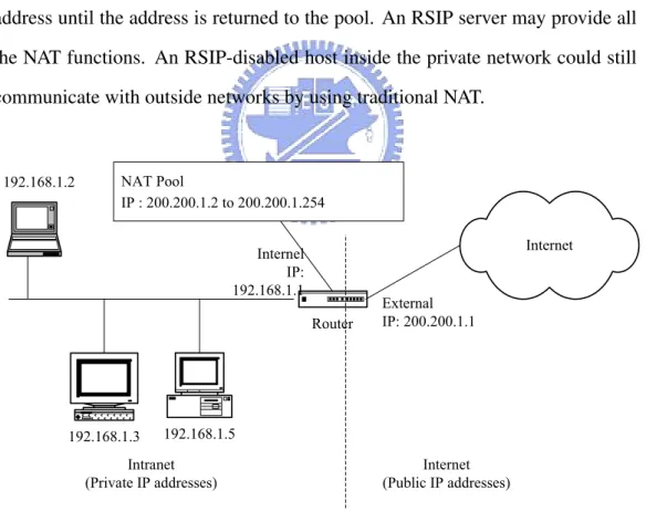
An RSIP server maintains a pool of IP addresses to be leased by RSIP clients. Upon client request, the RSIP server allocates a public address to the client. An RSIP client may lease more than one public address from the RSIP servers. Once an address is allocated to a particular client, only that specific client may use the address until the address is returned to the pool. An RSIP server may provide all the NAT functions. An RSIP-disabled host inside the private network could still communicate with outside networks by using traditional NAT.
192.168.1.5 192.168.1.3 Router Internet NAT Pool IP : 200.200.1.2 to 200.200.1.254 External IP: 200.200.1.1 Internel IP: 192.168.1.1 Intranet
(Private IP addresses) (Public IP addresses)Internet 192.168.1.2
As shown in Figure 2.3, an RSIP server C with two interfaces, 192.168.1.1 and 200.200.1.1, connects both public and private networks. Host A is an RSIP client with private address 192.192.1.5, and host B with address 140.113.216.164 belongs to public network. C has a pool of public IP addresses, 200.200.1.2 to 200.200.1.254, which it can assign to host A and other RSIP clients in private network.
When RSIP client A wants to connect to host B, client A first requests a pub-lic IP ad-dress, 200.200.1.5, from RSIP server C. Client A tunnels data packets across private network to C. C stripping off the outer headers and routing the inner packets to B. When a packet from B arrives at C, C will also tunnel those packets to A.
Since A can lease a public address from RSIP server C to communicate with B in public network, the end-to-end nature of the Internet connectivity is guaranteed in the RSIP architecture. Most of the ALG in NAT implementation is no longer required.
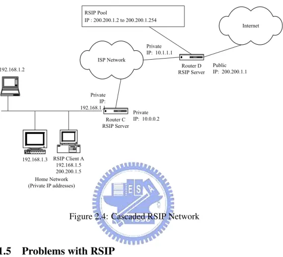
It is possible for RSIP to allow for cascading of RSIP servers. For example, consider an ISP that uses RSIP for address sharing amongst its customers. It might assign only a private IP address to a particular customer. This customer may use RSIP again in his home network. No matter how many levels of RSIP, RSIP servers only assign public IP addresses to client. As shown in Figure 2.4, if RSIP client A requests an IP address from the nearest RSIP server C, C leases one public address 200.200.1.5 for host A from RSIP server Ds public address pool.
RSIP Client A 192.168.1.5 200.200.1.5 192.168.1.3 Router C RSIP Server ISP Network Private IP: 10.0.0.2 Private IP: 192.168.1.1 Home Network (Private IP addresses) 192.168.1.2 Internet Router D RSIP Server RSIP Pool IP : 200.200.1.2 to 200.200.1.254 Public IP: 200.200.1.1 Private IP: 10.1.1.1
Figure 2.4: Cascaded RSIP Network
2.1.5
Problems with RSIP
RSIP provides a mechanism for end hosts to lease public IP addresses from RSIP server, which avoid the limitation of NAT. Hosts without RSIP client-enabled could still communicate with public network by using traditional NAT. However, RSIP ar-chitecture still has the following drawbacks:
First, the RSIP architecture does not concern about security issues to authorize or authenticate clients. The RSIP server cannot manage the resources efficiently, and it may meet the Denial of Service attack [11]. Second, The RSIP tunnel establishes be-tween client and server is not encrypted. Third, the RSIP server contains only one public addresses pool. Hosts in the public network cannot lease
private IP address from the RSIP server in the reverse direction. For example, consider a mobile host that uses other ISP to access the Internet. This mobile host cannot use RSIP to grant access to his home network.
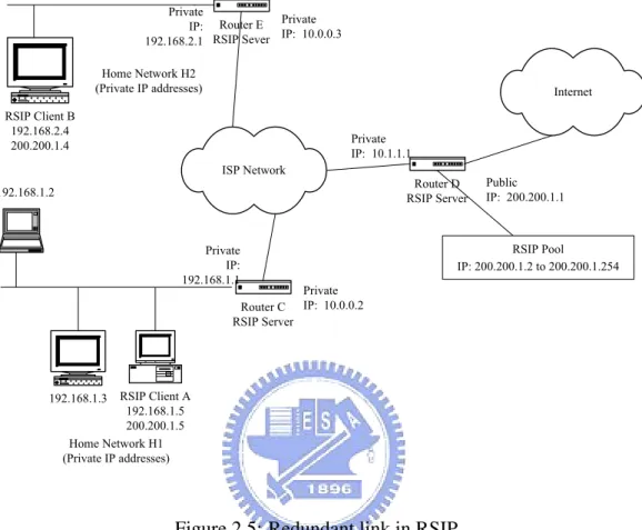
Furthermore, considering two customer-networks use cascade RSIP to con-nect to the same ISP, as shown in Figure 2.5. If RSIP client A that resides in home network H1 wants to communicate with RSIP client B that resides in home net-work H2, both of them should request public addresses from ISPs RSIP Server D. The communication link between RSIP client A and RSIP client B will be: client A → Router C → Router D → Router E → client B. Where the both the two pubic address and the two tunnels that setting up from Router C to Router D and Router E to Router D are unnecessary.
2.2
Multi-Homed networks
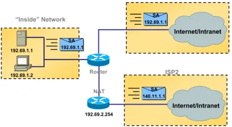
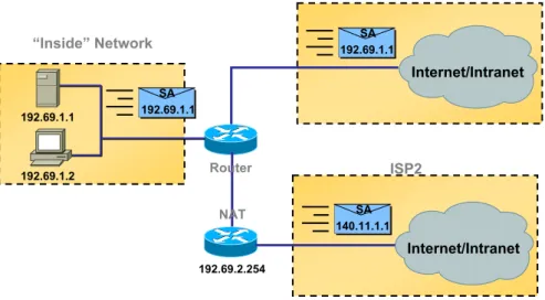
In a multi-homed network, a mobile host may have one or more network inter-faces. The network interfaces may support the mobile host one or more public IP address or private IP address. If the IP address is a private one, an NAT box is resides in the network. Here we summarize five different situations of the network architecture:
Case 1 The mobile host has only one network interface and the edge router has n links. The host A connects to a single network realm X; the edge router of realm X has one or more path to link to Internet. The IP address assigned to host A is a public IP address.
RSIP Client A 192.168.1.5 200.200.1.5 192.168.1.3 Router C RSIP Server ISP Network Private IP: 10.0.0.2 Private IP: 192.168.1.1 Home Network H1 (Private IP addresses) 192.168.1.2 Internet Router D RSIP Server Public IP: 200.200.1.1 Private IP: 10.1.1.1 RSIP Client B 192.168.2.4 200.200.1.4 Router E RSIP Sever Home Network H2 (Private IP addresses) RSIP Pool IP: 200.200.1.2 to 200.200.1.254 Private IP: 192.168.2.1 Private IP: 10.0.0.3
Figure 2.5: Redundant link in RSIP
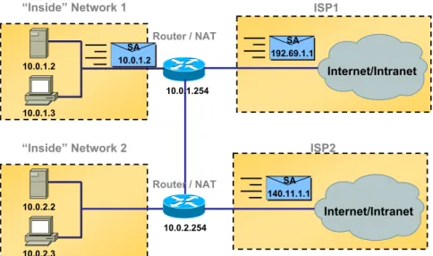
than one edge router with several interface to link to Internet. The IP address assigned to host A is a private IP address. NAT function is performed in the edge router.
Case 3 The mobile host has only one network interface and the edge router has n links. The host A connects to a single network realm X; the edge router of realm X has one or more path to link to Internet, whereby one NAT box is resides in one link. The IP address assigned to host A is a private IP address. Case 4 The mobile host A connects to several network realms; the IP addresses
assigned to host A are all public IP addresses. Each realm may contain several outbound links.
Case 5 The mobile host A connects to several network realms, the IP addresses assigned to host A may be public IP address or private IP address.
“Inside” Network 192.69.1.1 192.69.1.2 SA 192.69.1.1 Internet/Intranet SA 192.69.1.1 ISP2 Internet/Intranet SA 140.11.1.1 NAT Router 192.69.2.254
Figure 2.6: Multi-homed Network with NAT, case 1
To overcome the problems described above, the Internet Engineering Task Force (IETF) proposed two protocols to support terminal mobility among IP sub-nets, the Mobile IP protocol and the Stream Control Transmission Protocol (SCTP) [61]. However, both of them still contain several problems. In the mobile IP net-work, a mobile host sends a binding update message to perform a roaming op-eration when a mobile host migrates from one interface to another. If the home
“Inside” Network 1 10.0.1.2 10.0.1.3 SA 10.0.1.2 Internet/Intranet SA 192.69.1.1 ISP2 Internet/Intranet SA 140.11.1.1 Router / NAT Router / NAT 10.0.1.254 10.0.2.254 “Inside” Network 2 10.0.2.2 10.0.2.3 ISP1
Figure 2.7: Multi-homed Network with NAT, case 2
agent (HA) is unreachable at this time, the foreign agent (FA) cannot process this location update request. Packets send to mobile node (MN) cannot be forwarded to the newest location and the connection will be terminated.
Another two solutions are based on DNS: Round robin DNS and Dynamic DNS. Round robin DNS is usually used for balancing the load of geographically distributed Web servers, but can be used in a multi-homing environment. Dy-namic Domain Name System (DDNS) is a method of keeping a domain name linked to a changing IP address as not all computers use static IP addresses. An mobile host with DDNS supports will update it’s current IP addresses with the DNS server, which means other users just need to use DNS query to find out the current location of the mobile node.
“Inside” Network 192.69.1.1 192.69.1.2 SA 192.69.1.1 Internet/Intranet SA 192.69.1.1 ISP2 Internet/Intranet SA 140.11.1.1 NAT Router 192.69.2.254
Figure 2.8: Multi-homed Network with NAT, case 3
2.2.1
Mobile IP and mobile IPv6
In Mobile IP network [45], a mobile node (MN) gets a Home Address from its home agent (HA). When a mobile node handoffs to a foreign network, it gets a Care-of Address (CoA) from foreign agent (FA) and informs home agent (HA) its care-of address by sending a registration request message to the home agent. The home agent maintains the binding between the care-of address and the home address of each mobile node. When a valid binding for a mobile node exists, the home agent will capture all the packets sent from correspondent nodes (CNs) to the mobile node’s home address and forward them by tunneling to the care-of ad-dress. In MIPv6 [25], the mobile node uses can inform correspondent nodes about its current location by using a binding-update message; the correspondent nodes will be able to send packets directly to mobile node’s care-of address, instead of sending packets through mobile node’s home address.
2.2.2
SCTP protocol
The Stream Control Transmission Protocol (SCTP) [61] is an IP-based end-to-end, connection oriented transport protocol developed by the Internet Engineering Task Force (IETF) Signaling Transport working group for the transport of signal-ing data. However, SCTP is a general purpose transport protocol which provides numerous advantages over user datagram protocol (UDP) and transmission con-trol protocol (TCP). For instance, SCTP combines the datagram orientation of UDP with the sequencing and reliability of TCP. Additionally, SCTP uses multi-stream, message-oriented routing in multi-homed environments. SCTP provides applications with enhanced performance, reliability, and control functions.
SCTP protocol overview
In SCTP, data is transmitted between endpoints through a connection referred to as an association. An association begins with an initiation of a four-way hand-shake between two endpoints and is maintained until all data has been success-fully transmitted and received. Within SCTP, user data and control messages are assembled into chunks. An SCTP packet contains a common header and zero or more chunks.
SCTP message streams
The term ”stream” is used in SCTP to refer to a sequence of user messages that are to be delivered to the upper-layer protocol in order with respect to other messages within the same stream [61]. SCTP multi-streaming logically divides user data into unidirectional streams with each stream having its own delivery mechanism.
All streams within a single association share the same congestion and flow con-trol parameters. Through multi-streaming, SCTP eliminates unnecessary blocking that often occurs in TCP transmission.
In TCP, user data is delivery in a single sequence of bytes which is strictly ordered. This delivery mode results in a major drawback known as ”head-of-the-line blocking (HOL),” where messages are not allowed to bypass each other. Multi-streaming decouples data delivery and transmission, and in doing so pre-vents Head-of-Line blocking.
SCTP streams are effectively unidirectional channels, within which messages are usually transported in sequence, unless the user requests a message to be de-livered by an unordered service. The stream mechanism may reduce the effects of head-of-line blocking, especially in the case of a large number of small messages and a large number of stream. SCTP also provides a mechanism for unordered delivery service as UDP. User messages sent using this mechanism are delivered to the SCTP user as soon as they are received without any processing.
SCTP Multi-Homing
The SCTP supports multi-homed endpoints with more than one IP address. SCTP has a built in failure detection and recovery scheme, known as failover, which al-lows associations to dynamically send traffic to an alternative destination address when needed without losing the end-to-end association or requiring the applica-tion to intervene. This failover occurs after a threshold number of transmission timeouts to the primary destination address have occurred. SCTP also exploits this path redundancy in its retransmission policy.
2.2.3
IP round-robin and dynamic DNS
IP Round robin works on a rotating basis in that one server IP address is handed out, then moves to the back of the list; the next server IP address is handed out, and then it moves to the end of the list; and so on. Round robin DNS is usually used for balancing the load of geographically distributed Web servers. For example, a company has one domain name and three identical home pages residing on three servers with three different IP addresses. When one user accesses the home page it will be sent to the first IP address. The second user who accesses the home page will be sent to the next IP address, and the third user will be sent to the third IP address. In each case, once the IP address is given out, it goes to the end of the list. The fourth user, therefore, will be sent to the first IP address, and so forth. Although very easy to implement, round robin DNS has important drawbacks, such as those inherited from the DNS hierarchy itself and TTL times, which causes undesired address caching to be very difficult to manage. Moreover, its simplicity makes remote servers that go unpredictably down inconsistent in the DNS tables. However, this technique, together with other load balancing and clustering methods, can produce good solutions for some situations.
Dynamic Domain Name System (DDNS) [66] is a method of keeping a do-main name linked to a changing IP address as not all computers use static IP addresses. Typically, when a user connects to the Internet, the user’s ISP assigns an unused IP address from a pool of IP addresses, and this address is used only for the duration of that specific connection. This method of dynamically assign-ing addresses extends the usable pool of available IP addresses. A dynamic DNS service provider uses a special program that runs on the user’s computer,
contact-ing the DNS service each time the IP address provided by the ISP changes and subsequently updating the DNS database to reflect the change in IP address. In this way, even though a domain name’s IP address will change often, other users do not have to know the changed IP address in order to connect with the other computer.
2.3
Authentication protocols to be used in multi-homed
networks
Network users potentially need to access sensitive private data or digital sign transaction over the network, which means secure transmission of information over insecure communication channels is a major issue in current Internet. To build a secure communication environment in multi-homed networks, an authen-tication protocol is required. Authenauthen-tication protocol is an important technique to verify the identities of the communication parties when they start a connection. This service is usually provided in combination with a key generation scheme between the parties.
In recent years, a variety of protocols for authentication and key agreement have been proposed and applied to many communication environments. There are two different approaches to used in designing the authentication protocols: centralized or de-centralized.
Most current authentication mechanisms are based on the centralized approach, such as the well-known Kerberos authentication protocol [58], which required a trusted third party (key information center) between the communication parties.
In the Internet-scale multi-homing environment, the trusted third party becomes a bottleneck because the server should have enough computation power, network bandwidth and data storage to deal with large amount of users. When it is unable to process requests or vulnerable to attacks, millions people may be influence. Furthermore, in a large-scaled multi-homed network, the mobile host may not reach the server all the time.
Another approach is decentralized schemes. In a de-centralized authentication protocol, there are no central servers to deal with authentication and encryption, only two peers are involved in the communication. A lot of research has been done and many algorithms have been proposed to make the decentralized authentication schemes more secure [13, 35, 9, 42, 48]. Two of the famous decentralized authen-tication schemes are the RSA scheme and the Diffie et al’s public key distribution system [13, 35]. Both of them still need a server to keep user’s public information, and the correctness and security of that information must be guaranteed.
In a multi-homed network, it is better to use the decentralized authentication schemes because the communicating peers may come from different networks, which means communication with a central server is difficult.
To avoid the central server bottleneck to be occurred in large-scale multi-homed networks, identity-based (ID-based) authentication schemes are developed [9, 42, 48]. In an ID-based authentication scheme, the public information of a user, such as name and address, are used as user’s public key, which need not be stored in a central server. The first ID-based scheme proposed by Shamir [48], which rely on the existence of a trusted central authority, supports only digital sig-nature rather than message encryption. In 1989, Okamoto and Tanaka extended Shamir’s idea and combined digital signature and key distribution in a sample
ID-based scheme, which supports message encryption and withstands the conspiracy problem [42]. Okamoto and Tanaka’s scheme has the following problems: user identifications may be forged, user secret information may be disclosed, and the high overhead of exponential computations is needs. Tsujii proposed another ID-based cryptosystem, which suffers from the conspiracy problem, still needs high overhead of exponential computations.
2.4
Summary
In this chapter, we briefly introduce three major problems impacting the inter-net: the Network Address Translation (NAT), the multi-homing protocol such as Stream Control Transport Protocol (SCTP), and the authentication protocols to be used in the multi-homed networks.
NAT is considered a solution to the insufficiency of IPv4 address space. How-ever, if IPv6 is widely deployed on the Internet, address space will no more be an issue and we can obviate the need of NAT. Regardless of address space consider-ation, NAT can still be considered a solution in IPv6 for security or load-sharing concerns.
In the near future, Internet service providers may only provide NAT solutions to small enterprise networks due to the shortage of address space. In such trends, existing Internet security protocols must be re-examined together with this new network environment.
The Stream Control Transmission Protocol is an IP-based end-to-end, con-nection oriented transport protocol which is a general purpose transport proto-col which multi-stream, message-oriented routing in multi-homed environments.
SCTP provides applications with enhanced performance, reliability, and control functions.
Finally, we evaluate two different approaches to used in designing the authen-tication protocols: centralized or de-centralized. We found it is better to use the decentralized authentication schemes in the multi-homed networks.
Chapter 3
Multi-Layer RSIP Management
Architecture
With the growth of virtual private networks, a user hides in a private network may wish to communicate with other users reside in another private network. Most of the private networks use IP ranges 10.0.0.0/24, 172.16.0.0/16, or 192.168.0.0/8 defined by IETF [46]. The address collision problem may occur if both sides use the same address space. Currently both NAT and RSIP architectures not only lack server connection ability, but also cannot solve the address-collision prob-lem. Eun-Sang Lee et al. proposed an architecture that modified the mapping table inside NAT-server to provide server connection ability [33]. However, Lee’s architecture does not solve the end-to-end security problem.
In this chapter, we propose a new architecture, the MRSIP framework, to solve the above problems. The specific goals of our framework are as follows.
Each of the network hierarchies described in the above chapter addresses some of the deficits of Internet scaling problems. However, as has been pointed out
above, none of these architectures can be considered a completely satisfying solu-tion yet. The aim of MRSIP is to define a clear, simple, and flexible architecture which integrates the advantages of each of the abovementioned approaches while avoiding their disadvantages, and which provides a solid bases for adding new features in a consistent and straight-forward manner. The basic design objectives of MRSIP can be summarized as follows:
• Transparent-access capabilities with the private network. • Cascade private network architecture.
• Redundant path detection between source and destination nodes • Reduce the address-collision probability
Our proposed framework is useful in real world implementations. Our frame-work is also very well suited to small private netframe-works such as home netframe-works and security devices like firewalls.
3.1
System components and terminology
In order to convert a standard RSIP network into an MRSIP network, it is at least necessary to insert an MRSIP agent into the framework, and to replace all RSIP server and RSIP client to MRSIP server and MRSIP client, respectively. In the following, we will motivate and explain the functionality of the MRSIP network infrastructure.
• MRSIP Gateway
ad-dress realms and owns one or more IP adad-dresses in each realm that can be assigned to MRSIP clients. An MRSIP gateway contains two major com-ponents, the MRSIP server and the MRSIP agent.
• MRSIP Client
An MRSIP client replaces the original RSIP client with several modifica-tions: each time when MRSIP client initiates a new connection, it requests a new pair of IP/port resources from MRSIP gateway. When the connec-tion is terminated, the MRSIP client returns those resources back to MRSIP gateway. An MRSIP client may lease many IP/port resources for several communications at the same time.
• MRSIP Agent
An MRSIP agent provides the resource management, tunnel establishment, and redundant path detection. It manages resources that will lease to or re-turn from MRSIP clients or other MRSIP gateways. The MRSIP agent con-tains two addresses pools, the inner address pool with private addresses and the outer address pool with public addresses. In a cascade MRSIP frame-work, the outer address pool also contains private address.
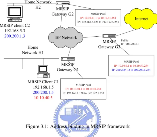
An MRSIP agent may lease its address to another MRSIP gateway. In Figure 1, the MRSIP agent C contains two address pools, 10.10.40.1 to 10.10.40.254 and 192.168.1.128 to 192.168.1.253, whereby both of them are private addresses. But agent C can request public addresses (200.200.1.2 to 200.200.1.254) from its parent RSIP gateway D.
The MRSIP framework is more portable compares to the original RSIP net-work by using the several address pools: hosts inside the private netnet-work
can request the public IP address and hosts outside can get private addresses to access local servers.
• MRSIP Server
The MRSIP server is responsible for tunnel establishment and data forward-ing with MRSIP clients and other MRSIP gateways. Consider that an MR-SIP client resides in a private network want to send data packets to the public network, the MRSIP client first register and requests a public IP from MR-SIP gateway, establishes a tunnel with the correspondent MRMR-SIP server, and encapsulates those data packets into that tunnel. The MRSIP server receives data in the tunnel, decapsulates those tunneled data packets, and sends them to the destination host.
Consider another case that both the source and destination hosts reside in two MRSIP private networks. When the MRSIP client requests an IP from a local MRSIP gateway, the MRSIP gateway forwards the request to the des-tination network’s MRSIP to get a private IP in the desdes-tination network. The MRSIP client establishes a tunnel to the local MRSIP gateway as mention above. Another tunnel is established between two correspondent MRSIP gateways. The MRSIP client uses the requested private IP and these two tunnels to reach the destination host.
3.1.1
Registration of MRSIP clients
When an MRSIP client startup, it first determines where is the location of the local MRSIP gateway, and sends a registration request to the MRSIP gateway. The MRSIP gateway checks the registration request and authenticates the client’s
identity. After that, it generates a client-ticket, inserts client’s information and this client-ticket to a host table, and returns this ticket to the client. The MRSIP client uses this ticket to do addressing binding before establishing a connection outside.
3.1.2
De-registration of MRSIP clients
When an MRSIP client determines it does not need RSIP service anymore, it sends a de-registration request with its client-ticket to the local MRSIP gateway. The MRSIP gateway checks the client-ticket and removes the client’s entry in its host table. If a specific interactive period timeout reached after the MRSIP client registered itself to the local MRSIP gateway, the MRSIP gateway deregister this specific client and removes the client’s entry automatically.
3.1.3
Address binding
As far as described in this paper, when the RSIP client requests an IP from the local RSIP gateway, the RSIP servers always returns a public IP to the client in the original RSIP framework. By the way, the original RSIP client cannot communicate with hosts resides in another private network, except the remote host is also an RSIP client that binds a public address already. To solve this problem, our modified MRSIP client requests IP in the destination realm. The link properties can be summarized as follows:
1. Both the source host and the destination host are all in the public network. 2. The source host resides in a private network, but the destination host is in
3. The source host is in public network but the destination host resides in a private network.
4. Both the source host and the destination host reside in private networks interconnected by the public network.
5. Both the source host and the destination host reside in private networks interconnected by a private network.
In case 1, the source host communicates with destination host by public IP directly. In case 2, the source host uses MRSIP client to request a public IP address from local MRSIP gateway and establishes a tunnel with MRSIP server.
In case 3, a public IP address should be previously assigned to the destination host. The source host should have the ability to query destination host’s IP address by dynamic domain name system or other service allocation protocols.
Now considering case 4, there are two approaches that can solve this problem. First, both source and destination hosts requests public IP address from MRSIP gateway to communicate with each other. This is the traditional RSIP strategy. The second approach required the source host requests a private address from the MRSIP gateway resides in the destination network. The source host estab-lishes tunnels from itself to the destination’s MRSIP server and uses that private IP address to communicate with the destination host. In the second approach, the destination host is no longer required to get a public IP previously.
In case 5, there are two approaches similar to the case 4. First, both source and destination hosts requests public IP address from MRSIP gateway to communicate with each other. All the data packets transmit from the sender are encapsulated in a tunnel routed to the public networks, and routed back to another encapsulated
tunnel to reach the destination. Figure 1 shows the example. Assume host A and B gets the public addresses 200.200.1.5 and 200.200.1.3 from RSIP gateway D, respectively.
This approach requires two unnecessary tunnels (Host A → Gateway C → Gateway D and Host B → Gateway E → Gateway D) and two public IP address (200.200.1.3 and 200.200.1.5). The public IP addresses are expansive resources to those large networks that only have a little range of public IP.
The second approach required the source host requests a private address from the MRSIP gateway resides in the destination network. The MRSIP gateways in both sides negotiate a shortest path between them, and establish a server-to-server tunnel within the path. The source host establishes a tunnel from itself to the local MRSIP gateway and uses that private IP address to communicate with the destination host. In the second approach, the data packets will not route to public network and no public IP address is required.
As shown in Figure 3.1, router C establishes a client-to-server tunnel from A to C and a server-to-server tunnel from gateway C to gateway E. Router C gives client A one private address 10.10.40.5, instead of the 200.200.1.5. Client A uses the leased private address and these two tunnels to communicate with client B
3.1.4
Address unbinding
The address unbinding procedure is happened when an MRSIP client returns the early requested session-ticket to MRSIP gateway when the correspondent com-munication is terminated. The MRSIP gateway drops all the tunnels between the source and the destination host correspondent to the specific session-ticket. The
MRSIP Client C1 192.168.1.5 200.200.1.5 10.10.40.5 MRSIP Gateway G1 ISP Network Home Network H1 Internet MRSIP Gateway G3 Public IP: 200.200.1.1 MRSIP client C2 192.168.5.3 200.200.1.3 MRSIP Gateway G2 Home Network H2 MRSIP Pool IP: 10.10.0.1 to 10.10.50.254 IP: 200.200.1.2 to 200.200.1.254 MRSIP Pool IP: 10.10.40.1 to 10.10.40.254 IP: 192.168.1.128 to 192.192.1.253 MRSIP Pool IP: 10.10.41.1 to 10.10.41.254 IP: 192.168.5.128 to 192.192.5.253
Figure 3.1: Address binding in MRSIP framework
released resources are put back to the MRSIP gateway’s resource pool that can be use for future requests.
3.1.5
Address collision avoidance
Assigning private address of the destination network to the source MRSIP client reduces the necessary of public IP address, but induces the probability of address collision. Most of the private networks use IP ranges 10.0.0.0/24, 172.16.0.0/16, or 192.168.0.0/8 defined in [46]. Considering Figure 3.2 and 3.3, if the RSIP client A with private address 192.168.1.5 wants to connect to host B and host F, whereby the addresses are all 192.168.1.3
To avoid the occurrence of address collision, when the MRSIP gateways detect an address collision during the address-binding step, the MRSIP gateways negoti-ate with other MRSIP gnegoti-ateways to replace the IP address one-side or both-side to prevent the collision. For example, consider when the MRSIP gateway C in Fig-ure 3.2 receives a connection request to Host B from MRSIP client A, gateway C first discover host B is inside its neighbor MRSIP network. It attempts to request a private address from MRSIP gateway E, assume it is 192.168.1.6. Gateway C then detects there is an address collision and then returns an alternate IP address 10.10.40.5 to host A from its own address pool to avoid the address collision.
MRSIP Client C1 192.168.1.3 10.10.40.5 MRSIP Gateway G1 ISP Network Home Network H1 Internet MRSIP Gateway G3 MRSIP client C2 192.168.1.3 MRSIP Gateway G2 Home Network H2 MRSIP Pool IP: 10.10.0.1 to 10.10.50.254 IP: 200.200.1.2 to 200.200.1.254 MRSIP Pool IP: 10.10.40.1 to 10.10.40.254 IP: 192.168.1.128 to 192.192.1.253 MRSIP Pool IP: 10.10.41.1 to 10.10.41.254 IP: 192.168.1.128 to 192.192.5.253
Figure 3.2: The address collision of two private networks (I)
In figure 3.3, when gateway C receives a connection request to Host B from MRSIP client A, gateway C first discover host B is resided in another MRSIP
network partition by a public network. It attempts to request a private address from MRSIP gateway E, assume it is 192.168.1.6. Gateway C then detects there is an address collision and then returns an alternate public IP address 200.200.1.5 to host A from its parent RSIP gateway’s address pool to avoid the address collision.
MRSIP Client C1 192.168.1.5 200.200.1.5 MRSIP Gateway G1 ISP Network Home Network Internet MRSIP Gateway G2 MRSIP Pool IP: 10.10.0.1 to 10.10.50.254 IP : 200.200.1.2 to 200.200.1.254 MRSIP Gateway G3 Host C2 192.168.1.3 MRSIP Pool IP: 140.113.216.2 to 140.113.216.254 IP: 192.168.1.128 to 192.168.1.254 MRSIP Pool IP: 10.10.40.1 to 10.10.40.254 IP: 192.168.1.128 to 192.168.1.254
Figure 3.3: The address collision of two private networks (II) caption
3.1.6
Security aspects
The original RSIP framework does not discuss about the security issue. The RSIP server does not identify its clients and assumes they should use IPsec or other encryption protocols to protect the packets. Also, the original RSIP client cannot access a server resides in a private network if the server does not have a public IP
address. Furthermore, the RSIP server cannot resist from denial of service attack if an attacker get all the public addresses from server’s IP pool.
In our proposed MRSIP framework, both MRSIP client and MRSIP server should prove there identify to the MRSIP gateway. The MRSIP gateway only pro-vides services for trust clients and servers. An MRSIP gateway controls whether a client can get a private address to access a specific private server. Even the MR-SIP gateway inhibits a client to use private address to access the specific server directly; the client may try to use public IP address to access the server.
3.2
Protocol specification
In this section, we define the parameters and the control message types that uses in our MRSIP framework. We provide a series protocol examples in section 3.3 to demonstrate how the MRSIP works.
3.2.1
Parameter specification and formats
In the original RSIP protocol specification [3] describes the parameters and con-trol messages. Our MRSIP framework extends the specification to provide the ability of authenticate clients and gateways. The extended parameters are de-scribed as follows:
• Client-ID:
A client-ID specifies an MRSIP client’s identity. The client-ID data struc-ture contains a unique 32-bit integers and a string that specifies client’s in-formation. The string can be a private IP address, user’s e-mail address, or
a certificate issued by a particular certificate-authority. • Gateway-ID:
A Gateway-ID is a string that specifies an MRSIP gateway’s identity. The Gateway-ID data structure contains a unique 32-bit integer and a string that specifies an MRSIP gateway’s identity information.
• Session-ID:
A Session-ID is a unique 32-bit integer that used by MRSIP clients and gateways to differentiate an MRSIP client’s bindings.
• Signature:
The signature is appended in the rest of each request or response message to authenticate the message.
• Client-Ticket:
A client-ticket is issued by a particular MRSIP gateway for a specific client after the registration procedure is succeeded. The client-to-gateway tunnel information and other server information are stored in the client-ticket. • Session-Ticket:
A session-ticket is issued by a particular MRSIP gateway for a specific client after the address binding procedure is succeeded. The session-ticket contains the assigned IP resources and other parameters given by the gate-way.
A gateway-ticket is issued by a particular MRSIP gateway for the other specific MRSIP gateway after the registration procedure is succeeded. The gateway-ticket contains the MRSIP gateway information.
• Tunnel-Ticket:
A tunnel-ticket is issued by a particular MRSIP gateway for the other spe-cific MRSIP gateway after the tunnel-binding procedure is succeeded. The tunnel-ticket contains the gateway-to-gateway tunnel information, and the IP addresses that can be provided by the remote gateways.
3.2.2
Control message types
In this section we describe the control message types that is used in our MR-SIP protocol. The MRMR-SIP control messages are based on the ”request-response” model. These control messages contains the register procedures, de-register pro-cedures, tunnel-establishment propro-cedures, address-binding propro-cedures, and host query procedures.
• Registration request and response:
An MRSIP client sends a registration request to its home MRSIP gateway to register itself before requests any resources. An MRSIP gateway should register itself to neighbor gateway before requests any resources or establish tunnels. Both MRSIP client and gateway should not register more than once before it has de-registered. An MRSIP client or gateway should provide his Client-ID or Gateway-ID and signature to the specific gateway, respectively. The registration response message is used by an MRSIP gateway to confirm
the registration of an MRSIP client or the other MRSIP gateway. A Client-Ticket or a Gateway-Client-Ticket is returned for future operations.
• De-registration request and response:
An MRSIP client or gateway de-registers itself to an MRSIP gateway when the connection is no longer required. If an MRSIP client de-registers itself, all of the client’s address-bindings are revoked. If an MRSIP gateway de-registers itself to the other MRSIP gateway, all of the address binding and tunnels are revoked. The de-registration response message is used by an MRSIP gateway to confirm the request.
• Tunnel-binding request and response:
The tunnel-binding request and response messages are used by an MRSIP gateway to establish a gate-way-to-gateway tunnel with the other MRSIP gateway. An MRSIP gateway should register itself to the specific MRSIP gateway to get one Gateway Ticket before establishing a tunnel between them.
• Free-tunnel request and response:
The free-tunnel request and response are used by an MRSIP gateway to free a tunnel. A tunnel is freed when all the address binding inside the tunnel are all freed.
• Address-query request and response:
An MRSIP client or an MRSIP gateway uses the address-query request mes-sage to ask an MRSIP gateway whether or not a particular address or
net-work is local or remote. The MRSIP client uses this information to deter-mine whether to contact the host directly or via MRSIP gateway. When an MRSIP gateway receives the query-request message, the gateway performs the following procedures if the queried address is not access directly by itself: first, it forwards the query request message to its neighbor MRSIP gateways and wait for response. Second, a tunnel-binding request message will be sent to a specific MRSIP gateway to establish a tunnel between them. Finally, it returns a response message to the client or gateway that sent the query message.
• Address-binding request and response:
An MRSIP client sends the address-binding request message to its home MRSIP gateway to bind an outside IP address. If the MRSIP gateway cannot allocate the resource requested by the client, it forwards the request to his neighbor gateway. A Session-Ticket is returned to the client and a client-to-gateway tunnel is established between the MRSIP client and its home MRSIP gateway.
• Free-Binding request and response:
When an address binding is no longer required by an MRSIP client, it sends the free-binding request message with a Session-Ticket to the MRSIP gate-way. MRSIP gateway frees the specific resources. If the resource is not own by the gateway, the gateway forwards the request to other MRSIP gateways. All the unused tunnels between client and gateway will be released.
3.3
Two protocol examples
In this section we describe two protocol examples of the MRSIP framework. An MRSIP client is denote by Cn, and an MRSIP gateway is denote by Gn, where n is a number to identify each entity. All MRSIP client-to-gateway traffic, gateway-to-client traffic and gateway-to-gateway traffic is denote by ’Cn→ Gn’, ’Gn→ Cn’, and ’Gn→ Gn’, respectively.
1. Client communicates with host resides in public network C1 → G1: REGISTER REQUEST
G1→ C1: REGISTER RESPONSE
The MRSIP client attempts to register with the gateway, the gateway re-sponds and assigning a client-ticket to the client.
C1 → G1: QUERY REQUEST
G1→ C1: QUERY RESPONSE
When the client C1 attempts to connect to other host C2, C1 sends a query
message to G1to retrieve C2’s address information. G1responds if C2is in
the foreign network or not.
C1 → G1: ADDRESS-BINDING REQUEST
G1→ C1: ADDRESS-BINDING RESPONSE
C1 determines that C2 is located in the public network; C1 attempts to
re-quest a public IP from the gateway G1 and establishes a tunnel between
C1 → G1 → C2: Data-Packets
C1uses the tunnel to communicate with C2.
C1 → G1: FREE-BINDING REQUEST
G1→ C1: FREE-BINDING RESPONSE
C1 ends the connection with C2 and releases the binding IP address to the
gateway.
C1 → G1: DE-REGISTER REQUEST
G1→ C1: DE-REGISTER RESPONSE
C1de-registers itself with the gateway.
C1 G1 C2 Register Request Register Response Query Request Query Response Address-Binding Request Address-Binding Response DATA DATA Free-Binding Response De-register Request De-register Response Free-Binding Request
2. Client communicates with hosts resides in another private network that par-tition with the public network between them
When the client C1 attempts to connect to other host C2, C1 registers with
it’s nearest gateway G1 and sends a query message to G1 to retrieve C2’s
address information.
G1→ G2: REGISTER REQUEST
G2→ G1: REGISTER RESPONSE
G1→ G2: QUERY REQUEST
G1 recognizes that C2 is resides in another private network that partitions
with the public network. G1tries to register itself to the remote gateway G2
to retrieve the C2’s information and send the result to C1. Fr
G2→ G1: QUERY RESPONSE
G1→ C1: QUERY RESPONSE
C1 → G1: ADDRESS-BINDING REQUEST
C1 determines that C2 is located in the foreign network; C1 attempts to
request a public IP from the gateway G1 and establishes a tunnel between
itself and the gateway.
G1→ G2: TUNNEL-BINDING REQUEST
G2→ G1: TUNNEL-BINDING RESPONSE
The gateway G1 forwards the address-binding request to G2 and return the
result to C1. A gateway-to-gateway tunnel from G1 to G2 is established
between the address request intervals. C1 → G1 → G2 → C2: Data-Packets
C1uses the tunnel to communicate with C2.
C1 → G1: FREE-BINDING REQUEST
C1ends the connection with C2 and releases the bound IP address to G1.
G1→ G2: FREE-TUNNEL REQUEST
G2→ G1: FREE-TUNNEL RESPONSE
G1→ C1: FREE-BINDING RESPONSE
Register Request Reguster Response Query Request Query Request Query Response Query Response
Address Binding Request
Tunnel Binding Request Tunnel Binding Response Address Binding Response
DATA DATA DATA
Free Binding Request
Free Tunnel Request Free Tunnel Response Free-Binding Response
C1 G1 G2 C2
Figure 3.5: Client communicates with hosts resides in another private network
3.4
Comparison
In this section, we compare the functionality of NAT, RSIP and MRSIP, as shown in table 3.1. According to table 3.1, the NAT has only limited function to connect to or from public network (an application level gateway maybe required). Both the RSIP and MRSIP network, which can get one IP address from the gateway,