轉酯化反應發展於微流道系統之研究
118
0
0
全文
(2) 轉酯化反應發展於微流道系統之研究 Development of real-time microfluidic reactor for the characterization of transesterification reaction. 研究生:黃美榕 Student:Mei-Jung Huang 指導教授:柯富 祥 Advisor:Dr. Fo-Hsiang Ko. 國 立 交 通 大 學 奈 米 科 技 研 究 碩 士 論 文. A Thesis Submitted to Institute of Nanotechnology College of Engineering National Chiao Tung University in partial Fulfillment of the Requirements for the Degree of Master in Institute of Nanotechnology June 2008 Hsinchu 300, Taiwan. 中 華 民 國 九 十 七 年六 月.
(3) Acknowledgment 本研究之得以順利完成,首先感謝恩師 柯富祥教授這兩年來對學生不論是 在學問研究方面及待人處世上的指導與教誨,以及對於研究內容及成果,均悉心 校閱與指正,師恩浩瀚,學生銘感於心。另外,在研究期間承蒙俊淇學長這一路 上的帶領,從一開始完全在狀況外的我,到現在能夠將論文完成,對本研究提供 諸多寶貴意見,使得論文更佳紮實,於此謹致誠摯謝意。 在研究所這兩年生活中,特別感謝其昌學長、佳典學長、銘清學長、亦儂學 長、志杰學長、群芳學姊、敬雅學姊、子銘學長的指導與照顧,教導我實驗室的 生態與做人處事的道理,從學長姐們的身上學到許多書本中沒學過的事物,讓我 受益良多。還有一路走來的同窗好友們中書、阿生、德玲、品麟的相互扶持與勉 勵;以及戰友依蓁常常聽我在抱怨並適時的給我建議,常賦予生活上以及精神上 的一劑強心針,在此致以無限的謝意。也感謝鄭捷學弟、柏軒學弟、嘉琦學妹、 玟菲學妹以及京璋學弟在實驗研究上的協助與幫忙。 最後我要感謝一路支持我的家人—因為有爸爸媽媽的支持,大姐、婷、跟小 蘭姐的關心及激勵,我才可以完成碩士學業,願將所有成就與你們分享。. I.
(4) 轉酯化反應發展於微流道系統之研究. 學生: 黃美榕. 指導教授:柯富祥 國立交通大學 奈米科技研究所 碩士論文. 摘. 要. 近年來,隨著奈米科技的日益進步,微小化系統也逐漸備受重視。微小化 系統是一門延伸各領域的學問,需要化學、物理、生物、光學等各工程學科的結 合製作與設計。能夠建立一個微小型系統並直接快速地偵測其中的生物或化學分 子,也就是將以往傳統大型複雜的分析裝置,提供體積縮小化、平行分析化、降 低生產成本及縮短反應時間等優勢,將對於分析及研究上提供重大的貢獻。 傳統上對與轉酯化反應多是利用鹼製程來進行催化油脂以生產脂肪酸酯 類,亦是生質柴油。因具有反應時間短、成本低廉等優點亦是目前有發展工 業化的製程,但是其中的廢液處理也造成嚴重的環境污染問題。若是利用脂 肪分解酶來進行催化油脂以生產脂肪酸酯類,是具有無污染、環保的優勢。然 而,較高的操作成本及冗長的反應時間是導致酵素製程不受青睞的最主要原 因。對於脂肪分解酵素純化分離取得不易,再加上酵素無法進行重複回收再. II.
(5) 利用,所以價格相較於鹼製程來的高昂。因此本研究注重於發展出一個可以 減少成本、縮小試劑體積及縮短反應時間的轉酯化反應偵測系統。 本研究中將利用微小化系統的優勢以探討生物分子於微流道系統的表現。由 於在實驗中,脂肪分解酶反應時間的長短取決於酵素的活性及酵素的安定性, 因此將酵素經過固定化程序來進行提昇酵素活性及安定性為一個非常重要的 步驟。我們利用化學蝕刻技術製作出形貌特徵為金字塔所形成的織構化表面, 並結合自組裝技術來固定脂肪分解酶,由於織構化的表面可用以增加脂肪分解酶 的鍵結及矽基材的穿透度,並進而發展出一套在微流道系統上偵測脂肪分解酶催 化三酸甘油脂反應的方法。 研究中利用偵測與分析轉酯化反應的方法有:藉由 可見光與紫外光吸收光譜 儀來測定,發現透射係數可以有判定的指標。實驗證實在不同反應時間中,穿透 度有不同的變化,可用以觀察轉酯化反應的發生,然而此種光譜偵測的方法並不 能確切地提供反應的轉化率;我們發現三酸甘油脂與脂肪酸酯類尾端氫原子化學 位移的差異,並根據此差異來利用核磁共振儀偵測轉酯化反應,可以得到實際的 反應轉化率;由於實驗中得知轉酯化反應對於光線有反應,因此我們利用這點結 合太陽能板與微流道系統發展出一套光電偵測平台,並藉由特定波長的光訊號經 由太陽能板以收集電子訊號。 實驗中,我們結合自組裝技術及化學蝕刻法以提高脂肪分解酵素經固定化程 序的活性及安定性,並整合微流道系統來克服轉酯化反應中酵素製程的缺點。最 後結合上述的偵測方法,以推測不同的方法對於轉酯化反應在微流道系統中的分 析結果。. III.
(6) Development of real-time microfluidic reactor for the characterization of transesterification reaction Student:Mei-Jung Huang. Advisor:Dr. Fu-Hsiang Ko. Institute of NanoTechnology National Chiao Tung University. ABSTRACT Recently, the microfluidic technology has become very important and widely used in many research fields such as biochemical technology, semiconductor technology and electronics technology. The microfluidic technology, the studies on the motion of fluid and particles through the microchannels, is an emerging field that has given rise to a large number of scientific and technological developments over the last years. In this study, we would like to develop a microfluidic reactor for production of the biodiesel of transesterification reaction. First, we immobilized lipase on the tetramethyl ammonium hydroxide (TMAH) textured surface with self-assembled monolayer (SAMs) of covalent bonding. The TMAH textured surface for anisotropic texturisation are usually growing pyramidal structures which are increasing the surface areas for lipase-immobilized and decreasing the reflectivity for advancing IV.
(7) light absorption. The immobilization of lipase on solid substrate is an essential step for many applications in the field of biocatalysis duo to the relevance for the performance to improve and optimize the lipase activity and stability. However, the transesterification by enzyme method is time-consuming compared to acid- or alkali-catalyzed. Development the microfluidic reactor system is an important way to improving the reaction rate and enhancing the conversion yield due to the high surface-volume ratio and advancing the mass and heat transfer. This experiment aims is to provide a new approach that could potentially analyze the real-time reaction of transesterification. Moreover, new generation of biosensors combining new bioreceptors with the ever-growing number of transducers is emerging. The microfluidic reactor transducers of analysis systems are used in the optical spectroscopy. (UV-Vis. spectroscopy). for. detecting. the. transmission. of. transesterification reaction. Following is detecting by nuclear magnetic resonance (NMR) for identifying the structure of biodiesel and then estimating the conversion of reaction. Since the response of transmission can be detected from transesterification reaction, the exploration of photo-electronic analysis, photodetector, can be used for monitoring the biocatalytic reaction in real-time. It is based on the phenomenon of different transmission and converted to electric signal. Since the detection of UV/Vis-NMR can confirm the conversion of transesterification and the detection of optical-electric. (UV/Vis-photodetector). can. be. real-time. monitoring. the. transesterification reaction. Combine with above analysis methods, the experiments provide a new approach for an easy and feasible way to analyze and detect the transesterification reaction.. V.
(8) Contents Acknowledgment………………………………………………………...I Abstract (Chinese) ……………………………………………………..II Abstract (English) ……………………………………………………IV Contents………………………………………………………………VI List of tables……………...…………………………………………..VIII List of Figures ………………………………………………………..IX Chapter 1: Introduction………………...…………………………………….…....1 1.1 Gener al I nt ro du ct io n………………………….. …….. ……… ….. ... 1 1.2 L it er at ur e s Re v ie w…… … ………… …… …. . ……. …………. … …4 1.2-1 Biosensors………………………….…………..……………………..........4 1.2-2 Micorfluidic Systems……………………………………………………8 1.2-3 Biodiesel Analysis………………………………………………………..13 1.3 M o t iv a t io n… … … … … … … … … …… … …… … … … … …… … . … 1 5 1.4 T hes is Or g an izat io n……………………..……………. .………. … 16 Chapter 2: Principles and Operations ……..……………………………….….....18 2.1. Transesterification Reaction........................................................................18. 2.2 2.3 2.4 2.5 2.6. Lipase................................................................................................................21 Texturisation of the Pyramidal Structure..........................................................24 Immobilizat ion Technology…........................................................25 Microfluidic System…......................................................................................28 Quantitative Analysis..……………………………………………………….29 2.6-1 Ultraviolet-Visible Spectrophotometer………..……………………...29 2.6-2 Nuclear Magnetic Resonance Spectroscopy………..…………………31 2.6-3 Photodetector……………………………………………………..….32. Chapter 3: Experimental …………………………………………………….….....33 3.1 3.2 3.3. The Texturing Process by TMAH…...............................................................33 Enzyme Immobilization………………………………………………..41 The Characterization of the Lipase-Immobilized…………….………………44 3.3-1 Bradford Quantitative Analysis……...……...……………….………44 3.3-2 Measurement of Lipase Activity…………………………..….……….45 3.4 Specific Activity and Relative Specific Activity……………..…….............47 3.5 Triglyceride Synthesis by Lipase-Catalyzed………………………………....48 3.6 Construction of a Microfulidic Reactor……………………………………...49 3.6-1 PDMS Molding………...…….……………...………………….……49 3.6-2 Adhesion of PDMS Elastomer to Substrate……...…………….…….51 VI.
(9) 3.6-3. Fabrication and Integration of the Microfluidic Reactor……….……..54. Chapter 4: Results and Discussion……………………………………….…….....58 4.1. Optimal Conditions of Anisotropic Texturisation…………………………..58 4.1-1 Surface Morphology of the Pyramidal Structure and Its Reflectivity Analysis………………………………………………………………58 4.1-2 Surface Energy of the Pyramidal Structure………………………64 4.2 Activity and Stability of Immobilized Enzyme……………………………67 4.2-1 Effect of pH on Lipase Activity and Stability…………….….………..68 4.2-2 Effect of Temperature on Lipase Activity and Stability………..……68 4.2-3 Effect of Lipase Concentration on Lipase Activity and Stability…...70 4.2-4 Quantitative Analysis of Lipase on the Textured Surface…….……..71 4.3 Alcoholysis of Transesterification Reaction………………………..……....72 4.4 Transesterification Reaction by Microfluidic Platform………………….…..76 4.4-1 Ultraviolet-Visible Spectrophotometer Analysis….……………...…...78 4.4-2 Transesterificationfrom NMR Analysis……………………...………82 4.4-3 Electrical Properties of Commercial Cell…………………….……...91 4.4-4 Analysis by Transesterification Reaction………………………...…..96 Chapter 5: Conclusions……….………………………………….……….....100 References………………………………………………………………………….102. VII.
(10) List of Tables Chapter 1 Table 1-1 Economical feasibility of biodiesel………………………………………..3. Chapter 2 Table 2-1 Various Biodiesel Production Processes…………………………………..19 Table 2-2 Biodiesel emissions compared to conventional diesel…………………….20 Table 2-3 Compare the different materials of microfabrication……………………...29 Table 2-4 Important terms and symbols for absorption measurements…………...…30. Chapter 4 Table 4-1 The measurement of and contact angle at different etching time by 1.19 % TMAH and 50 % of IPA solution at 80 0C………………………………..66 Table 4-2 The measurement of surface tension and total surface energy at different etching time………………………………………………………………..67. VIII.
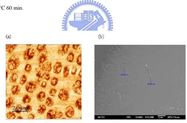
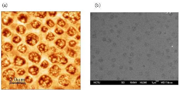
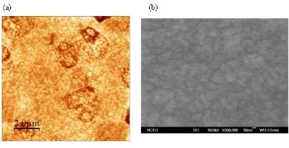
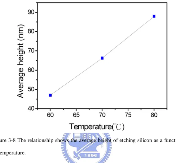
(11) List of Figures Chapter 1 Figure 1-1 A schematic representation of biosensors…………………………………1 Figure 1-2 A biosensor consists of a bioelement and a sensor element……………….2 Figure 1-3 The analytical curve obtained for H 2 O 2 , using the developed biosensor with Au–cysteamine–glutaraldehyde–HRP……………………………….5 Figure 1-4 Flow-cell set-up and fiber optic biosensor configuration………………….6 Figure 1-5 Working principle of glucose biosensors………………………………….6 Figure 1-6 Schematic view of the rotation of a F1 protein motor in a PDMS microchamber……………………………………………………………..9 Figure 1-7 Photograph of a fabricated microfluidic substrate with integrated photodetector chip…………………………………….………………….10 Figure 1-8 Images of immobilization technique for enzyme microreactor…………..12 Figure 1-9 The overall flow of this study…….………………………………………16. Chapter 2 Figure 2-1 Transesterification reaction of triglyceride……………………………….19 Figure 2-2 Products formed by lipase-catalyzed hydrolysis of triglycerides………...22 Figure 2-3 Structure of lipase in closed conformation and open conformation form..23 Figure 2-4 The bio and sensor element in biomaterial-sensor coupling can be divided into four general classes………………………………………………….27 Figure 2-5 Reflection and scattering losses with a solution contained in a typical glass cell……………………………………………………………………….29 Figure 2-6 The equation of Beer-Lambert low…………………………………….…30. Chapter 3 Figure 3-1 Anisotropic etching of silicon with 2.38 % TMAH solution in 60 oC 60min ………………………………………………………………………….34 Figure 3-2 Anisotropic etching of silicon with 2.38 % TMAH solution in 70 oC 60min ………………………………………………………………………….34 Figure 3-3 Anisotropic etching of silicon with 2.38 % TMAH solution in 80 oC 60min ………………………………………………………………………….35 Figure 3-4 The reaction of general texturing silicon surface……………………...…35 Figure 3-5 Anisotropic etching of silicon with 1.67 % TMAH solution and 30 % IPA in 60 oC 60min………………………………………………………......36 Figure 3-6 Anisotropic etching of silicon with 1.67 % TMAH solution and 30 % IPA IX.
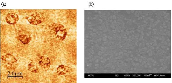
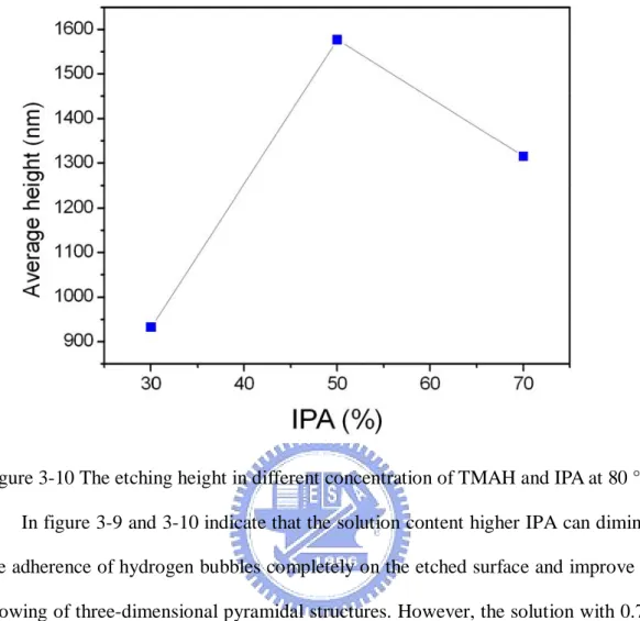
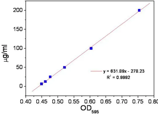
(12) in 70 oC 60min……………………………………………………….….37 Figure 3-7 Anisotropic etching of silicon with 1.67 % TMAH solution and 30 % IPA in 80 oC 60min…………………………………………………………..37 Figure 3-8 The relationship shows the average height of etching silicon as a function of temperature……………………………………………………………38 Figure 3-9 The morphology of AFM and SEM with different concentration of TMAH and IPA at 80 °C. 60 min…………………………………………………39 Figure 3-10 The etching height in different concentration of TMAH and IPA at 80 °C. …………………………………………………………………………..40 Figure 3-11 EDC reacts with a carboxyl group, forming an amine-reactive O-acylisourea intermediate……………………………………………….42 Figure 3-12 Reaction scheme for forming amide bonds with a self-assembled monolayer of 3-MPA on a gold surface…………………….…………….43 Figure 3-13 The typical standard curve of the Bio-Rad protein assay with BSA……45 Figure 3-14 The hydrolysis reaction of pNPP on the catalyst activity of lipase……..46 Figure 3-15 Illustration of PDMS mother mold…………………………………...…50 Figure 3-16 Example of the microreactor made of PDMS…………………………..51 Figure 3-17 The chemical structure of PDMS……………………………………….51 Figure 3-18 Schematic view of the adhesion between PDMS molding and glass Substrate………………………………………………………………53 Figure 3-19 Schematic diagrams of fabrication and integrations in microfluidic Reactor……………………………………………………….…………55 Figure 3-20 Schematic of the testing apparatus used for microfluidic system with syringe pump………………………………………………………….56. Chapter 4 Figure 4-1 The AFM and SEM texturing morphology of 1.19 % of TMAH and 50 % of IPA solution at 80 °C with varying time…………...………………….59 Figure 4-2 Average height of pyramidal structures with different time…………...…60 Figure 4-3 Comparison of different conditions of etching surface…………………..63 Figure 4-4 The reflectivity of silicon substrate with and without textursation process by N&K analyzer………………………………………………………64 Figure 4-5 The drop of DI water on the textured surface coated a gold thin film….66 Figure 4-6 Effect of optimal pH on the activity of free and immobilized lipase…….68 Figure 4-7 Effect of the optimal temperature on the activity of free and immobilized lipase……………………………………………………………………69 Figure 4-8 Effect of the optimal lipase concentration on the activity of free and X.
(13) immobilized lipase……………………………………………………….71 Figure 4-9 The quantitative analysis of lipase-immobilized on the substrate for 10 reused cycles……………………………………………………………..72 Figure 4-10 Schematic of lipase catalysis in the oil-water interface…………………73 Figure 4-11 Proposed model for the action of a soluble enzyme at an interface…….74 Figure 4-12 Schematic of microfluidic platform with the L-channel intersection…..77 Figure 4-13 Comparison of the transmission with different vegetable oils by alkali-catalysis…………………………………………………………..79 Figure 4-14 Measurement of the transmission spectrum by lipase catalyst with time.80 Figure 4-15 The relationship of transmission and catalysis time at 400nm………….81 Figure 4-16 Schematic diagrams of the chemical shift of CH 3 groups…………..….83 Figure 4-17 Comparison of 1H-NMR spectrum before and after transesterification by Alkali-catalyzed for previously observation the chemical shift position of triglyceride and esters………………………………………………..…85 Figure 4-18 Schematic of UV/Vis-NMR analysis system…………………………86 Figure 4-19 The 1H-NMR spectrums exhibit the chemical shift of CH 3 groups with triglyceride and eaters for each hour……………………………………88 Figure 4-20 Effect of lipase catalyses the transesterification reaction for the conversion increasing with time………………………..………………89 Figure 4-21 The relationship of transmission and conversion with the transeaterifacation reaction by lipase-catalyzed……………………..…90 Figure 4-22 Schematic view of photodetector……………………………………….91 Figure 4-23 I-V characteristic of photodetector with interdigitated lines……………92 Figure 4-24 Schematic of UV/Vis-photodetector analysis system…………………..93 Figure 4-25 The relationship of log current and voltage with solar cells which are stressed the voltage from -8V to 8V. The solar cell has better sensitivity under external negative bias operation in -5V…………………………..94 Figure 4-26 The I-t curve of lipase-immobilized on the solar cell and exposed to 400nm at bias of -5V……………………………………………………95 Figure 4-27 The relationship of transmission and current of solar cll with the transeaterifacation reaction by lipase-catalyzed…………………..…….97 Figure 4-28 The relationship of the transesterification reaction compared with the UV/Vis-NMR and UV/Vis-photodetector analysis system………….….98. XI.
(14) Chapter 1 Introduction 1.1. General Introduction The interdisciplinary study of biology, chemistry, and electronics becomes more. and more important than ever before. Combining the biotechnology and semiconductor technology, various types of biochips and biosensors have now been developed to detect and monitor the specific binding of biomolecular on the solid-state substrates. [1] The history of biosensors can trace back to 1962 with the development of enzyme electrodes by scientist Leland C. Clark. [2] Biosensors are known as immunosensors, optoelectrodes, chemical carries, resonant mirrors, glucometers, biochips, and biocomputers. The biosensors are described as a chemical sensing device in which a biologically derived recognition entity is coupled to a transducer, to allow the quantitative development of some complex biochemical parameter. And it is an analytical device incorporating a deliberate and intimate combination of a specific biological element and a physical element. A basic concept of biosensor in Fig. 1-1 and Fig. 1-2 shows it consists of a bioelement and a sensor element. The bioelement may be an enzyme, antibody, living cells, or tissue. The sensing element may be electric current, electric potential, and so on. [2]. Figure 1-1 A schematic representation of biosensors. [2]. 1.
(15) Figure 1-2 A biosensor consists of a bioelement and a sensor element. [2]. In this study, we try to develop a real-time microfluidic sensor and apply it for transesterification reaction detection applications. The sensor can be applied to green chemistry field. The biosensor is constructed by combining immobilized enzyme molecule as the bioelement, and the sensing element plays a role on optical element, electric current and chemical analysis. The transesterification reaction, in this process, is catalyzed by immobilized enzyme, lipase (triacylglycerol acylhydrolase, EC 3.1.1.3), for production of biodiesel fuel. Biodiesel has become more attractive because of its environmental benefits and the fact that it is made from renewable resources which indicates the vegetable oils or animal fats. The major advantage of biodiesel compared to other gasoline and petroleum diesel is that it is environmental 2.
(16) friendliness, and can be added in petroleum diesel with certain percentage to allay the energy issue. [3] As the rising energy demand and reducing petroleum reserves, fuels such as biodiesel and bioethanol are in the forefront of the alternative technologies. The price of bio-fuels will become more competitive to gasoline and petroleum diesel. Table 1-1 shows the economical feasibility of biodiesel. [4] However, there are some challenges for biodiesel fuel production, with lipase catalysis, from the following reasons: (i) reaction efficiency is poor and (ii) the stable activity of enzyme is necessary. In the thesis, we try to fabricate a microfluidic system which possesses the higher surface-to-volume ratios and lower reagents consumption. to the microfluidic system is expected to enhance the throughput rate of chemical synthesis and the amount of chemical product. [5]. Since the free enzyme for. transesterification loses its activity rapidly if it has no surface binding, we plan to retain the enzyme activity by means of immobilization onto the device surface.. Table 1-1 Economical feasibility of biodiesel.[4]. Biodiesel U.S. Europe. Petroleum. B100. B20. $1.5~2.0/gallon. $0.83~0.88/gallon. Vegetable oil. Waste grease. $0.54~0.62/l. $0.34~0.42/l. $0.68/gallon (taxes will add approximately $0.50 per gallon) $0.20~0.25/l. fiscal support from the government. B20 is nominally 20 percent biodiesel and 80 percent petroleum. B100 is 100 % pure neat biodiesel.. 3.
(17) 1.2 Literatures Review 1.2-1 Biosensors Biosensors are in general small devices based on direct spatial coupling between a biologically active compound and a signal transducer equipped with an electronic amplifier illustrated in figure 1-1. The response generated as a result of biochemical reaction is detected by a transducer to give a signal such as optical, electrical and thermal analysis in a given test sample. The biosensors can be of many types such as: resonant biosensors, optical detection biosensors, [6] thermal-detection biosensors, [7] ion-sensitive field-effect transistor (ISFET) biosensors,. [8] [9]. and electrochemical. biosensors. [6][7] The typically used bioelement enzyme is a large protein molecule that acts as a catalyst in chemical reactions but remains unchanged at the end of the reaction. The way of enzyme immobilization in the sensor has been investigated. It is an essential step for bioelement immobilization on the support materials. Mendes et al.. [11]. developed different immobilization procedures for horseradish peroxidase (HRP). The sensor of protein is efficiency immobilized on gold electrodes by different self-assembled monolayers (SAMs). The enzyme immobilization process uaes a cross linker to gold electrodes and modification with self-assembled monolayer which is constituted by structurally different thiols group that it is possible to develop distinct biosensors based on the –NH 2 terminal group of HRP.. [10]. The electrochemical. impedance spectroscopy and surface plasma resonance are used to evaluate the analytical response of the biosensor with respective to H 2 O 2 . In figure 1-3 shows the performance, which are confirmed that a larger extent of enzymatic adsorption onto the Au–cysteamine electrode, and suggests the promising to sensor promising for H 2 O 2 determination. 4.
(18) Figure 1-3 The analytical curve obtained for H 2 O 2 , using the developed biosensor with Au–cysteamine–glutaraldehyde–HRP. The linear response range, the detection limit and sensitivity presented by the proposed biosensor indicate that it can be used to determine hydrogen peroxide. [10]. A simple biosensor based on immobilized enzyme is developed for the monitoring of trace heavy metal ions. The biosensor system is designed based on the inhibition of urea activity, where the urea is immobilized on the membrane. When changing the pH, the bio-catalytic hydrolysis of urea changes the color from yellow to dark red, thus decreases in the reflectance response of the sensor measured at 615 nm by optical fiber sensor under the exposure to the heavy metal ions. [11] The construction of the optical biosensor is shown in figure 1-4. The immobilized urease and pH indicator strip are placed into the specially fabricated flow-cell with approximate 10 μL. The flow-cell device, with inlet and outlet for solution flow, is directly faced to the circular end of a fiber optic bundle probe. The bottom of flow-cell is PTFE disk in order to provide a reflective surface.. 5.
(19) Figure 1-4 Flow-cell set-up and fiber optic biosensor configuration. [11]. The most commercially successful biosensors are glucose biosensors. The first historic experiment that served as the origin of glucose biosensors is carried out by Clark and Lyons.. [2][12]. They utilize the phenomenon of glucose oxidation with a. glucose oxidase enzyme. The chemical reaction of glucose with oxygen is catalyzed in the presence of glucose oxidase shown in figure 1-5.. Figure 1-5 Working principle of glucose biosensors. [2]. 6.
(20) As soon as the enzyme recognizes the glucose molecules, it acts as a catalyst to produce gluconic acid and hydrogen peroxide from glucose and oxygen. In the meanwhile, the reaction also produces electrons, and protons, thus reduces glucose oxidase enzyme. The effect of interference is corrected by using platinum (Pt) electrodes, which is covered with the enzyme, and measuring the differential current. The chemical reaction of increasing the glucose content, the more oxygen is consumed. On the other hand, the lowering of glucose content results in more hydrogen peroxide generation. Hence, either the consumption of oxygen or the production of hydrogen peroxide can be detected with the help of platinum electrodes, and this can serve as a measuring indicator for glucose concentration. The biosensors are often used to cover sensor devices used in order to determine the analysis of substances and other parameters of biological. If the bioelement used as enzyme, the biological response of the biosensor is determined by the biocatalytic which converts the reactant to product. Immobilized enzymes possess a number of advantages which make them particularly applicable for use in such systems. It retains the activity and stability, which ensures that the same catalytic activity is present for a series of analyses. In the field of biosensors, there are various technical difficulties and more research efforts needed to find better alternatives. The bioelements and chemicals used in the biosensors are inevitable to be prevented from leaking out of the biosensor; biomolecules are attached to the transducer as strongly as possible; the detection range should develop to be large, selective and more sensitive, and research should be focused on the development of low-cost biosensors. At present, the development of faster, reliable, accurate, portable, and low-cost biosensors has become an important issue for the further applications in this field.. 7.
(21) 1.2-2 Microfluidic System The micorfluidic systems have several advantages for performing chemical reactions in comparison with the traditional technologies. The key advantages are the rapid heat exchange and rapid mass transfer, which cannot be achieved by the conventional batch system. As to the microfluidic systems used as analytical devices, the first approach is towards lab-on-a-chip devices. The lab-on-a-chip or micro-total-analysis system (μ-TAS) in conjunction with all of the components of the detection system has then to be integrated on a chip. These advances have also merged functions associated with sensing, actuation, and control to provide new platforms for chemical and biological research. The most important role of these systems is the function of analysis and detection system. Noji et al. [13] developed a technique capable of PDMS microchamber in order to perform single protein analysis. Figure 1-6 shows the microchamber of molding soft polymer PDMS onto glass substrate with dimensions of up to 2 μm in diameter and 2 μm in height. The measurement is to study the rotation activity of F1-ATPase protein (F1 protein) motors, by a single protein isolated in a microchamber. The activity can be estimated by the mechanical properties of rotary motor, F1 proteins hydrolyze ATP (adenosin-triphosphate) into ADP + P (adenosin-diphosphate + Phosphorous), and release energy which is converted into rotational torque. F1 proteins would rotate with the consumption of ATP molecules. As soon as the F1 proteins attach to the glass surface, they begin to rotate. The direction of the rotation is the same as that observed for the γ subunit and εsubunit, a kind of subunits with a stoichiometry consisted by the F1-ATPase. Rotation is absolutely dependent on ATP hydrolysis and inhibiting ATPase activity.. 8.
(22) Figure 1-6 Schematic view of the rotation of a F1 protein motor in a PDMS microchamber.. (a). A PDMS. microchamber. filled. with. buffer. and. one. F1-protein-coated bead, and (b) View of a microchamber with a bead rotating in chamber. The PDMS mold exhibits good property of optical detection in the visible and near-UV wavelengths. [14]. The PDMS microreactors are usually defined as miniaturized reaction systems fabricated by using the methods of microtechnology and precision engineering. Miniaturized analytical assays are useful in many fields of biotechnology. The possibility of performing similar analyses in parallel is an attractive feature. The microreactor is the proposed for a wide range of devices having small dimensions, and a further division according to size into nano, micro and minireactors. Most of the currently constructed microreaction devices take advantage of microfluidics, which enables use of micro- and nano-liter volumes of reactive species and ensures high efficiency as well as repeatability of biomolecular processes.. [15]. For the use of. microreactors in analytical chemistry and biochemical studies are that they can be coupled with numerous detection techniques such as fluorescence, absorbance, 9.
(23) electrochemical and chemiluminescence, and that pretreatment of the samples can be carried out on the chip. [16][17] Most spectroscopic detections are used for fluorescent tag or some photo-label attachment on the substance. The absorbance technique is advantageous as it does not require fluorescent tag attachment on the substance. In the UV or visible range most of the molecules or atoms absorb light at several wavelengths and then give a specific signature. Measuring the absorbing species in a sample solution is accomplished by applying the Beer-Lambert law. [14] Zhu et al. developed an integrated microfluidic UV absorbance detection system with attomol-level sensitivity for BSA.. [18]. The. fabrication for integration of bare photodetector chips into a polymer microfluidic substrate is shown in figure 1-7. Detection platforms fabricated using this approach exhibit exceptionally low concentration and mass detection limits down to 15 nM and 9.8 amol, respectively, for bovine serum albumin (BSA) as a model protein. Based on the Lambert–Beer relation, the sensitivity of the detection system can be increased linearly by increasing the optical path length. The integrated detector is potentially used for monitoring protein separations without resolution loss due to sample dispersion when passing through the detection region.. Figure 1-7 Photograph of a fabricated microfluidic substrate with integrated photodetector chip. [18] 10.
(24) Microfluidic systems, such as the enzymatic microreactors, have been developed in order to facilitate in biochemical analysis, and have applications in biocatalysis. The immobilization enzyme is often used with the achievements in chemical and biochemical microreaction. A centrifugal microchip that uses a compact disk (CD) player-like apparatus has also been described.. [19][20]. This method was applied to. antibody specificity, with the analysis process carried out by controlling the rotation speed shown in figure 1-8(a). This microfluidic system does not require the usual pump mechanism. Centrifugal and capillary forces were used to control the flow sequence of different solutions involved in the process. The microfluidic device was fabricated on a plastic CD. Each step of the analysis process was carried out automatically by controlling the rotation speed of the CD. This method is useful for the development of analytical microbioreaction systems for multiple analyses of single samples. Hisamoto et al.. [21]. reported that a nylon membrane could be formed at the. interface of two solutions formed in a microchannel shown in figure 1-8(b). Peroxidase is immobilized on this membrane, which is used as a chemicofunctional membrane. The synthesis of a chemically functional polymer membrane is reported by an interfacial polycondensation reaction and multilayer flow inside a microchannel. Single and parallel dual-membrane structures are successfully prepared by using organic/aqueous two-layer flow and organic/aqueous/organic three-layer flow inside the microchannel followed by an interfacial polycondensation reaction. Methods for the immobilization of enzymes on a microfluidic surface have also been developed because they can have the advantage of the larger surface area of microreaction systems. In these systems, a biotin–avidin system was most frequently used to immobilize enzymes. The biotinylated polylysine was physically immobilized on a glass surface to capture streptavidin-conjugated alkakine phosphatase 11. [22]. shown.
(25) in figure 1-8 (c). The device consists of a glass slide onto which enzyme has been immobilized in a well-defined region with a sharp interface that runs perpendicular to the direction of flow. By flowing substrate solution over the enzyme surface and measuring product concentration as a function of distance from the enzyme front, it can be determined the intrinsic kinetics of the reaction under steady-state conditions.. Figure 1-8 Images of immobilization technique for enzyme microreactor. (a) Schematic view of analysis structure CD and CD structure schematically drawn with a unit of eight parallel structures for analysis. (b) The membrane of a cross-linking enzyme-aggregate formed at microchannel surface. (c) The microreactor consists simply of a surface onto which enzyme has been immobilized. A Teflon gasket defines the walls of the channel. Flow over the surface is essentially uniform across the width of the channel. [19][20][21][22] 12.
(26) Numerous analytical micro enzyme-reactors have been developed that take advantage of the reduction in reaction time and the minimal amount of reagents used in microchannel systems. However, the range of immobilized enzymes available with satisfactory characteristics is still limited. The characterization of enzyme activity is a function of new biocatalysts and their substrates and the substrate concentration in the microreactors.. 1.2-3 Biodiesel Analysis Biodiesel is a renewable and a non-petroleum-based fuel made by a reaction of alcohol with vegetable oils, animal fats, or greases through a refinery process called transesterification reaction. The analytical methods of biodiesel discussed in this module can be divided into three categories: chromatographic methods,. [23] [24] [25]. spectroscopic methods, [26] [27] and physical-property based methods. [28] Chromatographic methods are used to separate a mixture of compounds based on theirbphysical chromatography. properties. (GC). The and. major. liquid. chromatographic chromatography. methods. (LC),. often. are. gas. termed. high-performance liquid chromatography (HPLC). In GC, the mixture is separated mainly by the boiling point and the structure of the individual compounds. To carry out a GC analysis, low concentrations of samples are usually dissolved in an organic solvent and then injected into the gas chromatograph. In this case, a sample needs to be derivatized with a silylating reagent in order to obtain a useful gas chromatogram. Derivatization improves their performance considerably, and can provide better resolution between compounds with similar properties. When the detector detects a material eluting from the column at a certain retention time, this will be shown by a peak in the chromatogram. Bunyakiat et al. [23] calculated the biodiesel conversion. 13.
(27) from GC analyses and standardization by the following equation:. Where W ME is the weight of methyl ester in liquid product that is obtained from gas chromatography; and W FA is the weight of fatty acid in each vegetable oil. Chiou and Wu. [24]. used LC to analyze the reaction production of biodiesel. LC. generally separates a mixture based on the solubility of its components in a solvent while passing the mixture through a column which is similar to GC. It is usually conducted at room temperature. Recently, spectroscopic methods that have been used for biodiesel include nuclear magnetic resonance (NMR) and near-infrared (NIR) spectroscopy. In both cases, certain characteristic peaks for oil and biodiesel in the spectra indicate how far the conversion of oil to biodiesel has progressed. NIR is easy to use and can give spectra in less than a minute. One of the advantages of these methods is that no derivatization is needed. Knothe. [27]. used 1H NMR spectroscopy for determining the. blend level of biodiesel in conventional diesel duel. Spectroscopic methods, on the other hand, give results in which all components of a mixture contribute simultaneously to the resulting spectrum. They can be used for quantification if appropriate components in the mixture exhibit unique peaks well separated from those of other components. Spectroscopic or chromatographic methods have been used most often for assessing biodiesel fuel quality and monitoring transesterification. In contrast to chromatographic methods, spectroscopic methods analyze the intact sample. However, it usually results in additional instrument costs. The chromatographic methods only detect if a compound is eluting, not its identity or structure. The identity or structure needs to be established through the use of standards as far as possible. Thus, using a. 14.
(28) spectroscopic method of detection in combination with a chromatographic method yields more detailed information. The most common analysis methods are GC-MS and LC-MS. Physical characterization methods are based on the difference in viscosity between the vegetable oil and the corresponding biodiesel. For example, the viscosity of soybean oil is 32.6 mm2/s at 38°C and that of biodiesel is 4.41 mm2/s at 40°C. The viscosity difference forms the basis of an analytical method for detecting by the viscometry applied to determining the conversion of vegetable oil to methyl ester. This can apply to monitor the progress of the transesterification reaction. It is noted that physical characterization methods do not provide much detailed analytical information than spectroscopic or chromatographic methods.. 1.3 Motivation The world energy demand issue continues to increase. The most feasible way to meet this growing demand is by utilizing alternative fuels. The biodiesel can be produced from transesterification reaction by means of chemical catalysis, acid- and alkali-catalyzed, and enzyme-catalyzed. The first two catalytic methods are received the greatest attention and used widely. As for the enzyme-catalyzed reaction, this reaction is considered natural and green. However, the reaction requires much longer reaction time and higher cost than other two methods. [23] For solving these problems, a new concept of micro systems needs to be developed. The special detection performed inside the microfluidic systems has the advantages in the fields of enhancing reaction efficiency. Furthermore, the microfluidic reactor requires much smaller sample volumes for the analysis system. This design conducts many measurements and consumes small volumes of samples, which is very importance for. 15.
(29) raising the price of feedstock materials recently. In this study, we would like to propose a new approach for the analysis and detection of transesterification reaction by means of fabricating a biosensor with enzyme-immobilized in microfluidic reactor system. The analysis of UV-Vis spectroscopy is an easy and feasible way of detecting the transesterification reaction, which idea has not been proposed for the detection of biodiesel before. Compared to other spectroscopic detections used fluorescent tag or some photo-label attachment on the substance, the UV-Vis method possesses the advantage of without any label such as fluorescent tag attachment. Under this approach, our ultimate goal is to develop a cheap and portable microfluidic reactor for faster production of the biodiesel. Our research demonstrates the potential application for the analysis and detection of transesterification reaction.. 1.4 Thesis Organization In this study, we report the enzyme-based biosensor of transesterification reaction for the production process of biodiesel. Our experimental flow is shown in figure 1-9.. Figure 1-9 The overall flow of this study. 16.
(30) The thesis is divided into five chapters. In chapter 1 is the general overview of the background and motivation of this study. Literature surveys the fabrication of biosensors, microfluidic systems, and reviews of biodiesel analysis. The principles and operations of this experiment are introduced in chapter 2. The detailed fabrication processes and immobilized steps are presented in chapter 3. In chapter 4, we discuss the activity of immobilized enzyme, microfluidic reactor performance and the analytical results of transesterification reaction. Finally, we summarize the contribution of our research in chapter 5.. 17.
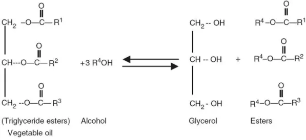
(31) Chapter 2 Principles and Operations 2.1. Transesterification Reaction Alkyl esters of short chain fatty acid are called biodiesel. ‘‘Bio’’ represents its. renewable and biological source in contrast to traditional petroleum-based diesel fuel; ‘‘diesel’’ refers to its use in diesel engines. We can obtain these esters (biosiesel) from triglycerides (oil) by transesterification with alcohol. Fig 2-1 shows the transesterification reaction of triglyceride. [4] The transesterification can be carried out by chemical, enzymatic or non-catalytic method.. [23]. The chemical method can. produce biodiesel and glycerol in the presence of a strong acid or base catalyst, in which normally be H 2 SO 4 and NaOH or KOH respectively. The alkali-catalyzed transesterification is much faster and less corrosive than the acid-catalyzed reaction and has been used for industrial scale. However, this reaction generates by-product i.e., waste water and requires high quality of feedstock during the producing of biodiesel. If oil has high free fatty acid and water content, acid-catalyzed transesterification reaction is more suitable.. [4][29]. The enzymatic one is. lipase-catalyzed which considered its energy-intensive process, but the high cost of enzyme and lower conversion of transesterification will be an important issue. Another approach is the non-catalytic, under supercritical methanol condition, just few minutes to product biodiesel and it is the fastest way of these methods. Because this type of non-catalytic method is under supercritical methanol condition, it takes most expensive production cost. [23] Table2-1 compares various biodiesel production processes.. 18.
(32) Figure 2-1 Transesterification reaction of triglyceride. And R1, R2, R3, R4 represent various alkyl group. [4]. Table 2-1. Various Biodiesel Production Processes. [4][23][29-30] Chemical Acid Condition. Enzyme. Non-catalytic (Supercritical). Near R.T.. >239.4 0C >8.09MPa. Alkali 0. 30~65 C. 60~80 0C. Reaction rate Middle (1hr~) Fast (30min~1hr) Slow (1hr~). Fast (sec~min). Waste water. Yes. No. No. Yield. Normal to high Yes. Low to high. High. Note points. 1. Low cost. 2. Suitable for high FFA and water content. 3. Difficult to purification. 4. Complicated process.. 1. High cost. 1. High cost. 2. Enzyme inactivity. 2. Large amount of 3.Environment-frien supercritical methanol. dly process. 3. Easy to purification. 4. Lower conversion 4. Only need to remove yield compare to methanol in the end of chemical method. process.. Yes 1. Low cost. 2. Need high quality TG. 3. Difficult to purification. 4. Anhydrous alcohol process.. FFA: free fatty acid TG: triglyceride. 19.
(33) Transesterification of triglycerides (vegetable oils and animal fats) to generate esters and glycerol to obtain a new engine fuel (biodiesel) is a well-prove process. Renewable biomass has also been considered as potential feedstock for vegetable oils to produce biodiesel. The main advantages of biodiesel as diesel fuel are liquid nature portability, ready availability, renewability, higher combustion efficiency, lower sulfur and aromatic content and higher biodegradability.. [3]. Table 2-2 shows the. biodiesel emissions compared to conventional diesel. Table 2-2 Biodiesel emissions compared to conventional diesel. [4]. As the energy is shortage and contamination problem around the world recently, the regeneration, biocompatibility, biodegradability, and environmental acceptability of biomass become noteworthiness theme. Although this is an environment-friendly process, the high price of biodiesel will be an important issue. The high price of biodiesel is in large part due to the high price of the feedstock and another part is depends on the price of the crude petroleum. [4] Nowadays more and more countries including Netherlands, Germany, Belgium, Austria, USA and Japan not only develop their renewable biomass process, but also promulgate the policy or tax relief to encourage people using the renewable biomass. 20.
(34) 2.2 Lipase In this experiment, we would like to generate esters through biocatalytic reaction with enzymes, lipase (triacylglycerol acylhydrolase, EC 3.1.1.3), which can normally be placed into three types by different positional specificities shown in figure 2-2. [31] [32]. A.. Non-specific lipase: This kind of lipases can completely catalyze the triglycerides to free fatty acid and glycerol. Examples of this type of lipases are Candida rugosa, Corynebacterium acnes and Stephylococcus aureus. And they show no marked specificity as regards the position on triglycerides molecule.. B.. 1, 3-specific lipase: The second type of lipases catalyses the release the fatty acids from the outer 1- and 3-positions glycerides specifically. 1, 2(2, 3)-diglycerides and 2-monoglycerides are chemical unstable and undergo acyl migration to give 1, 3-diglycerides and 1(3)-monoglycerides, respectively. Examples of the lipases are generated from Aspergillus niger and Rhizopus arrhizus species.. C.. Fatty acid specific lipase: The lipases catalyses the specific release of a particular type of fatty acid from glycerides. Most extracellular microbial lipases show little fatty acid specificity.. 21.
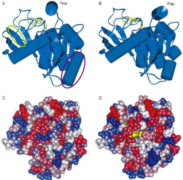
(35) (i) Nonspecific lipase:. (ii) 1, 3-specific lipase:. (iii) Fatty acid specific lipase:. Figure 2-2 Products formed by lipase-catalyzed hydrolysis of triglycerides. [31] [32]. Above-mentioned, we choice the Candida rugosa lipase as the biocatalysis enzyme because the non-specific lipase and the commercial availability in large quantities at a relatively low cost. Lipases can catalyze the hydrolysis and synthesis of esters at lipid/water interfaces, a phenomenon known as interfacial activation, which involves the displacement of a surface structure named the lid. [23] Lipases show a ‘lid’ controlling access to the active site which is yellow part in figure 2-3. The lipase three-dimensional structures were the first revealed by X-ray crystallography in 1990. [33]. And the interfacial activation might be due to the presence of an amphiphilic. peptidic loop covering the active site of the enzyme in solution, just like a lid or flap.. 22.
(36) Figure 2-3 Structure of lipase in closed conformation (A, C) and open conformation form (B, D). The purple one stands for and β strands and the green one is α helices. Upon opening of the lid, the catalytic triad (yellow) becomes accessible (D), and the region binding to the interphase becomes significantly more apolar. [33]. The lipases, whose structure has been constructed by members of the α/β-hydrolase fold family with a common architecture, compose of a specific sequence of α-helices and β-strands.[33] A lid is amphlpathic structure, and lipase used as catalysts in aqueous as well as water media. Interface-activated lipases occur in alternative conformation states with different activity: in the close conformation, the. 23.
(37) hydrophilic side faces the solvent, whereas the hydrophobic one is directed towards the protein core. The lid covers the enzyme active site, making it inaccessible to the substrate molecules. On the other hand, in open conformation the hydrophobic side faces the solvent, and the enzyme active site becomes exposed to the substrate-binding region.[31][33] Therefore, not only the amphipathic nature of the lid but also its specific amino acid sequence might be of importance for activity and specificity of lipases.. 2.3 Texturisation of the Pyramidal Structure There are lots of researches for random pyramidal texturing structures, due to decrease reflectivity of silicon solar cells and increase the short circuit current of the devices.. [34]. Anisotropic etching of silicon plays an important role for fabricating. various three-dimensional structures such as thin membranes and silicon microbridges for solar cell systems and IC processing. [34][35] The most commonly and simple way is using chemical etching solutions, NaOH or KOH. However, these chemical solutions containing K+ or Na+ ions are toxic, pollutant and the passivation layers (SiO 2 or SiN) deposited on the surface of the cell are contaminated after texturisation. An alternative to texturisation is tetramethyl ammonium hydroxide (TMAH). It was found that TMAH is not pollutant, not toxic and its use leads also to good etching characteristics of a pyramidal structure. [34-36] Moreover, the etching rate and surface morphology can be controlled by the etching parameters, such as concentration of the solution, temperature and the addition of surfactant. In this study, we investigate the etching process of silicon wafers with TMAH solutions of varying concentration under different temperature and surfactant conditions. This experiment with texturing the silicon substrates can generate the. 24.
(38) pyramidal structures which provide that aims of increasing the surface areas and decreasing reflectivity. The appearance of increasing surface areas has better perform of the immobilization lipase on the surface compared to the substrate without pyramidal structures. When decreasing the reflectivity, it can convert light signal to electric signal more completely, which has the same characteristics with solar cell. [37]. 2.4 Immobilization Technology The technology of immobilization is using chemical or physical method to immobilized enzyme onto the support or substrate. Enzymes are often immobilized onto solid supports to increase their thermal and operational stability, and recoverability.. [31]. Immobilization of enzymes has generally been used to obtain. reusable enzyme derivatives. This enables recycling of the biocatalyst and hence lowers the cost. The most important part of biosensor is the immobilization of a desired enzyme. Furthermore, the usefulness of immobilized enzyme depends on factors such as the immobilization method, the chemical and physical conditions (pH, temperature and contaminants), thickness and stability of the membrane used to couple the enzyme. [7] Various methods available for enzyme immobilization of biosensor can be showed in figure 2-4: membrane entrapment, physical adsorption, matrix entrapment, and covalent bonding, the four general classes: [2] A.. Membrane entrapment is based on entrapment of a solution containing the biologically active material on the surface of the sensor using a semipermeable membrane. In the scheme, a semipermeable membrane separates the analyses and the bioelement, and the sensor is attached to the bioelement. Membrane must have pores that small enough to retain the biologically active material, 25.
(39) and be matched to the biosensor so that it does not affect the response of transducer. B.. Physical adsorption is based on a combination of van der Waals forces, hydrophobic forces, hydrogen bonds, and ionic forces to attach the biomaterial to the surface of the sensor. This simplest method of immobilization is exposed to the biological material on the surface directly. Because of the weakly bond in molecule the sensor performance might be affected in changing of temperature, pH value.. C.. Porous entrapment is based on forming a porous encapsulation matrix around the biological material that helps in binding it to the sensor. And it is typically accomplished by formation of a gel containing biologically active material. This kind of method would not produce toxic by-products, and will increase the reactive areas by fixed biological components. D.. Covalent bonding is treated as a reactive group to which the biological materials can bind. This method is using chemical adsorption much stronger, thus biosensor lifetime would be longer. And the biological active material is directly on the surface of the sensor, thus it can reduce response time. The surface treatment to immobilize biomolecules, ex: Self-assembly monolayer (SAM): functional groups for coupling with proteins, such as NH 2 , COOH, SH, silane.[24]. 26.
(40) Figure 2-4 The bio and sensor element in biomaterial-sensor coupling can be divided into four general classes (a) membrane entrapment, (b) physical adsorption, (c) matrix entrapment, and (d) covalent bonding. [2]. As mentioned above, there are several methods for immobilization of enzymes. Some of these ways might have disadvantages and change the performance of enzyme .For example, the physical adsorption method is prone to leaching and shows instability whereas the covalent linking results in reduced activity of the biomolecule.[7] However, according to the researches ninety percent of the soluble enzyme was immobilized, and the immobilized enzyme was substantially more stable than the free enzyme.[38] The free enzyme lost its activity rapidly, and we could retains enzyme activity by immobilization technology method. In this experiment, we immobilized the enzyme onto the substrates by chemical methods, which covalent bonds are formed with the lipase. Protocols for covalent enzyme immobilization often begin with a surface modification or activation step.. 27.
(41) 2.5 Microfluidic System The microfluidic technology, which studies the motion of fluid and particles through the microchannels, is an emerging field that has given rise to a large number of scientific and technological developments over the last years. Microfluidics technology currently in development could have a revolutionary impact on the next generation of assays, particularly as lab-on-a-chip applications.. [39]. The history of. microfluidics technology starts in the early 1950s, when an effort to dispense small amounts of liquids in the nano and subnanoliter ranges, which basically is today’s ink-jet technology. Common methods of fabricating microfluidic devices and systems are including valves, mixers, and pumps, capable of controlling fluid flow by utilizing the physics of the microscale (μL) or nanoscale (nL). [40] Fluid flow at the microscale exhibits unique phenomena that can be leveraged to fabricate devices and components capable of performing functions useful for chemical reactions and biological operations. In miniaturization size of experiment enable precise control of the decreasing fluid volumes and reduce consumption of reagents and improve of controlling over the mass and heat transfer.[5] Because of the large surface-to-volume ratio of small fluid flow, microscale reactions might occur much faster and be revolutionized in the fields of high-throughput synthesis and chemical production. The materials of microfluidic devices have been fabricated in silicon, glass. [42]. or quartz. [43]. [41]. because of the similar technology available in the. microelectronics industry. However, for applications in the biochemistry field and polymeric materials are a desirable choice because of their lower cost, good possibility, and biocompatibility. [40] Table 2-3 lists the comparison of the materials of polymers and other substrates. [40-44] In this study, we would like to use the elastomer. 28.
(42) polymer material, polydimethylsiloxane (PDMS), an inexpensive one but powerful material and it offers several advantages compared with silicon or glass. Table 2-3 Compare the different materials of microfabrication. [40-44] Matrerial. Polymer. Silicon. Glass. Quartz. Feature aspect ratio. >10:1. >10:1. 2:1. >10:1. <1μm. <1μm. <1μm. fair. fair. Minimum feature size <1μm. Bioassay compatibility Fair to very good fair Optical detection. Good to excellent Poor to fair Good. Cost. Inexpensive. excellent. Inexpensive Inexpensive expensive to expensive. 2.6 Quantitative Analysis 2.6-1 Ultraviolet-Visible Spectrophotometer In optical detection, the ultraviolet-visible molecular absorption spectroscopy is based on the measurement of transmittance and absorbance. There is a linear relationship between concentration absorber (c) and absorbance (A) in figure 2-5, 2-6 and table 2-4. [45]. . Figure 2-5 Reflection and scattering losses with a solution contained in a typical glass cell. In this example, the light passes through the air-glass, glass-solution, solution-glass, and glass-air interfaces. [45] 29.
(43) Figure 2-6 The equation of Beer-Lambert low, [c] is linearly related to absorbance. [45]. The radiation of initial radiant power P0 is attenuated to transmitted power P by a solution containing c moles per liter of absorbing solution with a path length of b centimeters. Table 2-4 Important terms and symbols for absorption measurements. [45] Term and symbol. Definition. Alternative name and symbol. Incident radiant power, P 0. Radiant power in watts incident on sample. Incident intensity, I 0. Transmitted radiant power, P Radiant power transmitted by sample. Transmitted intensity, I. Absorbance, A. Log(P 0 / P). Optical density, D ; extinction, E. Path length of sample, b. Length over which attenuation l, d occurs. Concentration of absorber, c concentration in specified units Molar absorptivity, ε. A/bc. Molar extinction coefficient. In this study, we use ultraviolet-visible spectrophotometer to analyze the protein quantitative method of lipase-immobilized. We also found that the reaction before and after transesterification would change its characteristics of the transmittance at the wavelength of 400 nm. According to this phenomenon, we can detect the transesterification reaction of optical responses with time.. 30.
(44) 2.6-2 Nuclear Magnetic Resonance Spectroscopy Determining the structures of compounds is an important part for chemistry synthesis. Nuclear magnetic resonance (NMR) spectroscopy helps to identify the carbon-hydrogen framework of the compound. This instrumental technology not only identifies the functionality at a specific carbon but also determines what the neighboring carbons look like. Therefore, NMR can be used to determine the entire structure of a molecule. The most important applications for the organic chemist are proton NMR (1H-NMR) and carbon-13NMR spectroscopy. NMR spectroscopy developments have coincided with leaps in technology, such as readily available dedicated computers for Fourier transformation, efficient spectrometer control, and stable high-field superconducting magnets.. [46]. In principle, NMR is applicable to any nucleus. possessing spin. The electrons are changed, spinning particles with two allowed spin states of nuclei: +1/2 and -1/2. Spinning charged nuclei generates a magnetic field of a small bar magnet. In the absence of an applied magnetic field, the nuclei spin are randomly oriented. However, if the sample in an applied magnetic field, the nuclei twist and align in the larger magnet. [47] In this experiment, we have discussed the compound of triglyceride (oil) and esters (biodiesel) with different groups of protons. Therefore, this difference in the spin dynamics inspired us to analyze the structure of these two compounds by 1H-NMR spectroscopy.[27] Furthermore, we can estimate the yields in percentage for production of biodiesel by calculating the relative peak position and areas of the NMR spectra.. 31.
(45) 2.6-3 Photodetector Photodetectors are devices used for detection of light and converted electric signal from optical radiation with the source of visible, infrared, or ultraviolet wavelength. The important issues of these detectors are its signal to noise ratio, spatial resolution, ability to operate through a range of high to low input light levels, and spectral response. They are often used in sensing objects or encoding data by a change in transmitted or reflected light. There are many types of photodetectors which may be appropriate in a particular case: [48] A. Photodiode is a semiconductor device with p-n or p-i-n junction, where detects of light and generates a photocurrent. A particularly sensitive device is avalanche photodiodes, which can potentially provide higher gain bandwidth performance. B.. The metal-semiconductor-metal (MSM) photodetector is containing two Schottky barrier contacts of doped semiconductor material. The MSM device can be used as a photodetector by shining light on the top surface of the structure. When light impinges the electrodes of the semiconductor, it generates electric carriers, and is collected by the electric field and thus can form a photocurrent.. C.. Phototransistor is similar to photodiode but relatively more complicated to fabricate and generally require sizeable chip area. However, it is attractive for detection applications since it can achieve high gain through transistor action. In this experiment, we integrated the photodiode device, such as a solar cell,. and microfluidic systems for real-time sensing the transesterification reaction by lipase-immobilized on the solar cell surface.. 32.
數據
![Figure 1-4 Flow-cell set-up and fiber optic biosensor configuration. [11]](https://thumb-ap.123doks.com/thumbv2/9libinfo/8738585.203769/19.892.244.672.119.417/figure-flow-cell-set-fiber-optic-biosensor-configuration.webp)
+7
相關文件
Reading Task 6: Genre Structure and Language Features. • Now let’s look at how language features (e.g. sentence patterns) are connected to the structure
volume suppressed mass: (TeV) 2 /M P ∼ 10 −4 eV → mm range can be experimentally tested for any number of extra dimensions - Light U(1) gauge bosons: no derivative couplings. =>
incapable to extract any quantities from QCD, nor to tackle the most interesting physics, namely, the spontaneously chiral symmetry breaking and the color confinement..
• Formation of massive primordial stars as origin of objects in the early universe. • Supernova explosions might be visible to the most
• elearning pilot scheme (Four True Light Schools): WIFI construction, iPad procurement, elearning school visit and teacher training, English starts the elearning lesson.. 2012 •
(Another example of close harmony is the four-bar unaccompanied vocal introduction to “Paperback Writer”, a somewhat later Beatles song.) Overall, Lennon’s and McCartney’s
When ready to eat a bite of your bread, place the spoon on the When ready to eat a bite of your bread, place the spoon on the under plate, then use the same hand to take the
The min-max and the max-min k-split problem are defined similarly except that the objectives are to minimize the maximum subgraph, and to maximize the minimum subgraph respectively..
