Electric Power System Analysis and
Design of an Expanding Steel Cogeneration Plant
Cheng-Ting Hsu Chao-Shun Chen Chia-Hung Lin
Member, IEEE Senior Member, IEEE Member, IEEE
Department of Electrical Engineering Department of Electrical Engineering Department of Electrical Engineering Southern Taiwan University I-Shou University Kaohsiung University of Applied Sciences
Tainan, Taiwan Kaohsiung, Taiwan Kaohsiung, Taiwan cthsu@ mail.stut.edu.tw cschen@ mail.nsysu.edu.tw [email protected] Abstract --This paper presents the electric power system
analysis and design of an expanding steel cogeneration plant. The power system configuration and the equipment parameters of the cogeneration plant are well designed according to the power flow, short circuit, voltage fluctuation, harmonic flow and transient stability analyses. According to the power flow analysis, the site and capacity of shunt capacitor banks as well as the tap position of transformers are determined to maintain all the buses voltage at acceptable range and to keep the power factor above 0.95. Also, to comply with the restriction of circuit breaker capacity, the high impedance transformers are designed even if they consumed more reactive power from the system. In addition, the voltage fluctuation resulted from the dramatic reactive power variation of hot strip rolling mill can be greatly reduced if proper static var compensator (SVC) is installed. The significant voltage sag due to the starting of induction motor can be effectively improved by applying wye-delta transformer starter. Furthermore,the total voltage harmonic distortion (THDV) and the total current demand distortion (TDDI) are both acceptable if the proper filters are installed. It is also found that the cogeneration system can keep stable operation in isochronous mode by applying the governor control action and the load shedding scheme after tie line tripping. It is concluded that the power system analyses is important for the steel plant with cogeneration unit to identify hidden problems and remedy strategy to ensure the system power quality and operation performance.
Index Terms-- Power system analysis and design, Power quality, Cogeneration plant
I. INTRODUCTION
This paper presents the power system design and analysis of an expanding steel plant. The existing plant makes steel by applying DC arc furnace and has a H-beam welding line. To increase the amount and diversity of products, the plant is planning to build many new mills like blast furnaces, basic oxide furnaces and hot strip rolling mill. After that, it will become an integrated steelmaking plant for converting iron into finished products. It is very important to provide power supply with high quality and high reliability to these continuous operation equipments. In addition, to make use of the waste gases which are the by product of the iron making and to enhance the reliability of power system, many cogeneration units are considered to be installed in the steel plant. These new equipments and cogeneration units will make a significant impact on the planning and operation of the steel plant. It is therefore necessary to perform the various power system analyses for providing better system planning and operating strategy to enhance power quality and reliability.
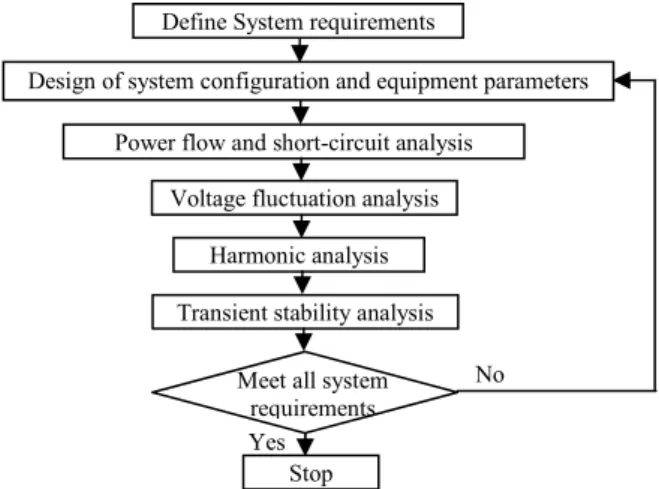
First of all, to ensure the power system can be operated more effective under various normal operation scenarios, power flow analysis can be applied to determine the parameters and setting values of the equipment. Also, the installation site and proper capacity of shunt capacitor banks can therefore be determined accurately. The short circuit analysis has to be executed because the new cogeneration units will contribute significant fault current, which is necessary for the determination of the rating of circuit breakers and to meet the utility requirement. It is also found that there are many large loadings in the steel plant such as the hot strip rolling mill and induction motor starting which may introduce serious voltage fluctuation problem. To solve this problem, the SVC is proposed to provide the adaptive reactive power compensation and the wye-delta starting [1] is applied for the large induction motor. Harmonic analysis is also performed for the design of harmonic filters to solve the distortion problem introduced by many harmonic sources like arc furnace, rectifier, cycloconverter, etc. in the steel plant. When an severe external fault contingency occurs, the cogeneration system should be disconnected from the utility as soon as possible by activating the protective relay to trip the tie line [2]. For the isolated cogeneration system, it is very important to perform the transient stability analysis to ensure the stable operation in isochronous mode can be maintained by applying the accurate governor action [3] and the proper load-shedding scheme [4-5]. Fig. 1 shows the flowchart of this study project for the design of power system configuration and the equipment parameters according to the simulation results of power flow, short circuit, voltage fluctuation, harmonic flow and transient stability analyses.
Fig. 1. The flowchart of this study project This work is supported by the China Engineering Consultants, Inc. and
the National Science Council of Taiwan, ROC, under Grant NSC 98-2221-E-218-053-MY2.
Define System requirements
Design of system configuration and equipment parameters Power flow and short-circuit analysis
Voltage fluctuation analysis Harmonic analysis Transient stability analysis
Stop Meet all system
requirements Yes
No
II. DESCRIPTION OF ELECTRIC POWER SYSTEM
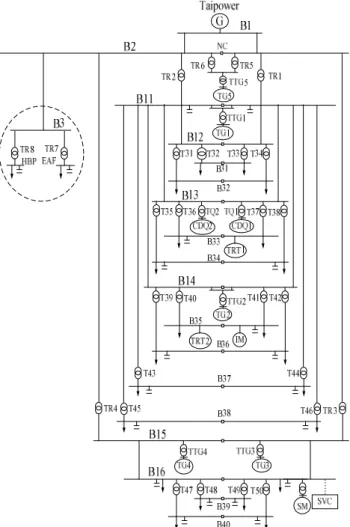
Fig. 2 shows the one line diagram of the steel cogeneration plant. For the power quality and reliability consideration, the steel cogeneration plant has to connect with Taipower system (bus B1) via double circuits of 3.6km, 161-kV transmission lines. The dashed line enclosed area is the existing power system which includes a DC arc furnace served by transformer TR7 with a 33-kV voltage level as well as a ladle furnace and an H-beam plant served by transformer TR8 with a 22.8-kV voltage level. In addition, several equipments like blast furnaces, basic oxide furnaces and hot strip rolling will be installed for the expansion of the steel plant. It is therefore to construct six new 33-kV buses (B11-B16) to serve the new loads in the plant. The 33-kV buses will be connected to the incoming 161-kV bus B2 via step-down transformers TR1-TR6. By the way, many 11.5-kV buses are also built to receive the electric power through transformers T31-T50. To make use of the waste gas which is the by product of the iron making and to enhance the reliability of power system, five steam turbines (TG1-TG5), two top pressure recovery turbines (TRT1-TRT2) and two coke dry quenching (CDQ1-CDQ2) type turbines are considered to drive the cogeneration units. The total rated generation capacity of all cogeneration units will reach 529MW in the integrated steel plant. Table I lists the parameters of the main transformers in the cogeneration plant.
Fig. 2. One line diagram of the steel cogeneration plant
TABLEIPARAMETERS OF THE MAIN TRANSFORMERS
Transformer Voltage (kV) Rated Capacity (MVA) Impedance (%)
TR1-TR6 161/33 120 18.5 TR7 161/33 160 12 TR8 161/22.8 72 14 T31-T50 33/11.5 40 11 TTG1-TTG2 33/13.8 100 22 TTG3-TTG5 33/13.8 80 22
III. POWER FLOW AND SHORT CIRCUIT ANALYSIS
To ensure the power system of the integrated steel plant can be operated in a more effective manner under various normal operation scenarios, power flow analysis is applied to determine the parameters and setting values of the equipment. The short circuit analysis is also used for the calculation of fault current to ensure the safety of bus bars and the sufficient capacity of circuit breakers.
3.1 Power Flow Analysis
In this section, the operation scenario with total generation of 321MW and total loading demand of 533MW is selected for computer simulation. The terminal voltage of cogeneration units is adjusted to be 1.01pu while the tap position of generator step-up transformers is set as 101.25%. Furthermore, many capacitor banks with a total capacity of 196Mvar are installed at different sites for reactive power compensation. It is found that all the bus voltages can be maintained within 0.970pu~1.012pu and the cogeneration plant has to import electric power of 216MW from Taipower with a 0.964 lagging power factor at point of common coupling (PCC) to meet total load demand in the plant. All equipments can be operated within their rating capabilities. However, a very large reactive power loss of 89Mvar, which is nearly 28% of the loading demand, has been observed due to the adoption of a 22% high impedance generator step-up transformers.
3.2 Short Circuit Analysis
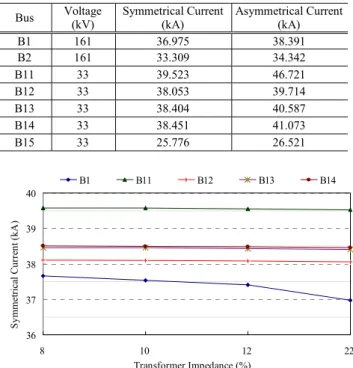
The generators and large motors in the cogeneration plant as well as external Taipower system will contribute a significant short circuit current when system fault occurs. The interrupting current of circuit breaker at 161-kV level is limited to 50-kA. However, it does not allow more than 40-kA for circuit breaker at 33-kV level due to limited space and other consideration. Up to now, the maximum short circuit capacity at Taipower 161-kV substation (bus B1) is 9132MVA. Therefore, the step-up transformers for cogeneration units are designed with a high impedance of 22% to reduce the fault current to meet the requirement of short circuit capacity in the plant. Table II lists the fault currents at main buses of the study system with a three-phase bolted ground fault. It is found that the critical site in the cogeneration plant is at power house mill (bus B11) because its fault current has reached to 39.523-kA. Fig. 3 shows the fault current at many main buses by considering various impedance values of transformers. Although bus B11 is still the critical site, the fault current has only been increased a little and reach 39.579-kA if the impedance of transformers is selected as 8%. On the contrary, the reactive power loss can be reduced from 89Mvar to 76Mvar.
TABLEIIFAULT CURRENTS AT MAIN BUSES OF THE STEEL PLANT
Bus Voltage (kV) Symmetrical Current (kA) Asymmetrical Current(kA)
B1 161 36.975 38.391 B2 161 33.309 34.342 B11 33 39.523 46.721 B12 33 38.053 39.714 B13 33 38.404 40.587 B14 33 38.451 41.073 B15 33 25.776 26.521 36 37 38 39 40 8 10 12 22 Transformer Impedance (%) S ym m et ri ca l C urre nt (k A) B1 B11 B12 B13 B14
Fig. 3. Fault current with various transformer impedances
IV. VOLTAGE FLUCTUATION ANALYSIS
The operation of many large loading in the steel plant will result in serious voltage sag and fluctuation problem [6]. In this paper, the voltage fluctuation resulted from the operation of hot strip rolling mill (HSRM) and the starting of large induction motors are simulated by considering the power system software [7] and the maximum reactive power fluctuation method [8] as described in (1).
max sc
max X Q
V ≅− Δ
Δ (1)
,where ΔVmax is the maximum voltage deviation, ΔQmax is
the maximum reactive power variation and Xsc is the short
circuit reactance at the measurement site.
4.1 HSRM Operation
The HSRM (bus B16) receives electric power from the 161kV main power station (bus B2) via TR3 and TR4 transformers to step down the voltage to 33kV level. The cycloconverter drive system is applied for the control of the synchronous motors to execute the steel plate rolling process. The working condition of the cycloconverter system consists of two types of drivers. One driver is used to drive the synchronous motors with a lower rotating speed for the rough rolling, while the other one is used to drive the synchronous motors with a higher speed for the finish rolling. Figs. 4 and 5 show the active and reactive power consumption for a typical rolling process, respectively. It takes about 105 seconds to complete the rolling process of one steel plate. The operation modes of finish rolling (F1-F7) and rough rolling (R1-R2) are determined by the automatic control according to the output torques required for each rolling stage. It is observed that the active and reactive power loading will reach the maximum values of 111.5MW and 98Mvar, respectively.
Fig. 4. Active power loading of the hot strip rolling
Fig. 5. Reactive power loading of the hot strip rolling 4.1.1 HSRM Operation Without Any Compensations
This section executes the voltage fluctuation analysis due to the operation of HSRM without any compensations. Table III shows the simulation results by performing the power system application software. Before the start of rolling process, the voltage at HSRM 33-kV (bus B16) is 0.983pu while the loading demand of the HSRM is 29.02MW and 18.82Mvar. The cycloconverter drive system will control the synchronous motors to roll the steel plate top and bottom repeatedly to change slab size into plate size. With the operation characteristics of the hot strip rolling, the active and reactive power consumption are varied dramatically at each rolling pass to result in the severe voltage fluctuation. It is observed that the minimum voltage is dropped to 0.876pu when the reactive power consumption of HSRM reaches the maximum value of 117.48Mvar at R2 rolling pass. At the same time the largest voltage deviation of 10.7% and the worst power factor of 0.766 is also found.
In this paper, the maximum voltage deviation is also calculated by applying the maximum reactive power fluctuation method. For the same working condition, the maximum reactive power variation (ΔQmax) due to the
operation of synchronous motors is 0.98pu if the system base is chosen as 100MVA. Thus, the short circuit reactance can be further calculated as
pu 095 . 0 8 . 1048 100 MVA MVA X sc base sc= = = (2)
where MVAsc is the three-phase short circuit capacity of
1048.8MVA at bus B16. The ΔVmax can be calculated as
9.3% by applying (1). The mismatch of the maximum voltage deviation between the two methods is only 1.4%. It is therefore acceptable to calculate the voltage deviation by using the maximum reactive power fluctuation method.
Fig.15. Mechanical output power response of the TG1-TG5 generator turbines for nearby disturbance case
VII. CONCLUSIONS
This paper presents the electric power system analysis and design for an expanding steel plant with cogeneration units by performing the analysis of power flow, short circuit, voltage fluctuation, harmonic flow and transient stability. It is found that all equipments can be operated successfully within their rating capabilities based on the designed configuration and selected parameters under various operation scenarios. However, the cogeneration system will be operated in a more effective and flexible manner if the impedance of generator step-up transformers can be reduced from 22% to 8%. Also, the voltage fluctuation resulted from the operation of hot strip rolling can be maintained within 5% and power factor can keep above 0.95 if proper capacitor banks and SVC are installed. By the way, the voltage sag due to the starting of induction motor can be improved from 0.88pu to 0.94pu by adopting the wye-delta starter method. Furthermore, the harmonic distortion, THDV and the TDDI, at PCC can be reduced to
0.45% and 0.43%, respectively by the implementation of the proposed passive filters. For the severe external fault in Taipower system, the cogeneration units can maintain the stable operation in isochronous mode by applying the governor control action and executing the load shedding scheme after the tie line tripping. It is concluded that the power quality and operation performance of the steel plant can be effectively enhanced by performing various power system analyses for the design of system configuration, equipments and operation strategy.
VIII. REFERENCES
[1] R. C. Dugan, M. F. McGranaghan, S. Santoso and H. W. Beaty,
Electrical Power Systems Quality, McGraw-Hill, 2004.
[2]C. S. Chen. C. T. Hsu and Y. D. Lee, "Protective Relay Setting of Tie Line Tripping and Load Shedding for an Integrated Steel-making Cogeneration System," IEEE Trans. on Industry Applications, vol. 46, no. 1, pp. 38-45, 2010.
[3] B. Kroposki, R. Lasseter, T. Ise, S. Morozumi, S. Papatlianassiou and N. Hatziargyriou, "Microgrids Management," IEEE Power & Energy
Magazine, pp. 40-53, May, 2008.
[4] K. Methaprayoon, W. J. Lee, S. Rasmiddatta, J. R. Liao and R. J. Rose, "Multistage Artificial Neural Network Short-Term Load Forecasting Engine With Front-End Weather Forecast," IEEE Trans.
on Industry Applications, vol. 43, no. 6, pp.1410-1416, 2007.
[5] C. T. Hsu, C. S. Chen and J. K. Chen, "The Load-Shedding Scheme Design for an Integrated Steelmaking Cogeneration Facility," IEEE
Trans. on Industry Applications, vol. 33, no. 3, pp. 586-592, 1997.
[6] M. H. J. Bollen, Understanding Power Quality Problems: Voltage
Sags and Interruptions, New York: IEEE Press, 2000.
[7] CYME PSAF User Guide, CYME International Inc., Saint-Bruno, QC, Canada, 2007.
[8] New Trend in Supply Problems of Arc Furnace for Steel Plants, Japanese Electrical Engineering Society, vol.2, no.72, pp.3-26, 1978. [9] IEEE Special Stability Controls Working Group, "Static Var
Compensators Models for Power Flow and Dynamic Performance Simulation," IEEE Trans. on Power Systems, vol. 9, pp. 229-240, Feb., 1994.
[10] A. Arulampalam, M. Barnes, N. Jenkins and J. B. Ekanayake, "Power Quality and Stability of a Wind Farm Using STATCOM Supported with Hybrid Battery Energy Storage," IEE Proceedings on
Generation, Transmission and Distribution, vol. 153, no. 6, pp.
701-710, 2006.
[11] J. Arrillaga and N. R. Waston, Power System Harmonics, John Wiley & Sons, 2004.
[12] K. S. Smith and L. Ran, "Input Current Harmonic Analysis of Pseudo 12-Pulse 3-Phase to 6-Phase Cycloconverters," IEEE Trans.
on Power Electronics, vol. 11, no. 4, pp. 629-640, July 1996.
[13] Z. Wang and Y. Liu, "Modeling and Simulation of a Cycloconverter Drive System for Harmonic Studies," IEEE Trans. on Industrial
Electronics, vol. 47, no. 3, pp. 533-541, June 2000.
[14] P. M. Anderson and A. A. Fouad, Power System Control and
Stability, New York: IEEE Press, 1993.
[15] IEEE Recommended Practice for Excitation System Models for
Power System Stability Studies, IEEE Standard 421.5, 1992.
[16] IEEE Working Group Report, "Hydraulic Turbine and Turbine Control Models for System Dynamic Studies," IEEE Trans. on
Power Systems, vol. 7, pp.167-179, 1992. IX. BIOGRAPHIES
Cheng-Ting Hsu (M’98) was born in Taiwan in 1963. He received the
B.S., M.S, and Ph.D. degrees in electrical engineering from the National Sun Yat-Sen University, Taiwan in 1986, 1988, and 1995, respectively.
From 1990 to 1992, he was with Phoenixtec Power Company Limited as a power electronics engineer, developing UPS equipment. He is currently a Professor of Electrical Engineering, Southern Taiwan University of Technology, Tainan, Taiwan. His research interests include the cogeneration system design, distributed generation, power quality, and stability analysis.
Chao-Shun Chen (SM’07) received the B.S. degree from National
Taiwan University, Taiwan, Taiwan, R.O.C., in 1976 and the M.S. and Ph.D. degrees from the University of Texas at Arlington in 1981 and 1984, respectively, all in electrical engineering.
From 1984 to 1994, he was with National Sun Yat-Sen University as a professor. From 1993 to 1997, he was with the Kaohsiung Mass Rapid Transit Department as the Deputy Director to be in charge of electrical and mechanical system planning. He is currently a full professor with the Electrical Engineering Department at the I-Shou University and a joint professor at National Sun Yat-Sen University, both in Kaohsiung, Taiwan. His research interests include the distribution automation, cogeneration systems, electrical, and mechanical system of mass rapid transit networks. Dr. Chen is a registered professional engineer in Taiwan.
Chia-Hung Lin (S’95-M’98) received the B.S. degree from National
Taiwan Institute of Technology in 1991, M.S. degree from University of Pittsburgh in 1993, and Ph. D. degree in Electrical Engineering from University of Texas at Arlington in 1997.
He is presently a full professor at National Kaohsiung University of Applied Sciences. His area of interest is distribution automation and computer applications to power systems.