C
ROSS
-L
AYER
D
ESIGN
INTRODUCTION
Internet protocol (IP) technology is increasingly being adopted as a conventional service platform for both data and speech services. Meanwhile, IEEE 802.11 wireless local area networks (WLANs) have been widely deployed as infras-tructures providing high-speed data services to mobile users. However, offering voice over IP (VoIP) services on WLANs is still considered problematic due to an inherent limitation of the IEEE 802.11 MAC protocol — the very long handoff process.
VoIP service can be provided on WLANs, where mobile nodes (MNs) equipped with IEEE 802.11 network interfaces send streaming IP packets through access points (APs) to the
Inter-net. When an MN detects poor link performance (e.g., low received signal strength or signal-to-noise ratio, high frame error rate), the MN may have to change its point of attachment to the Internet from one AP to another in order to retain its connection. The link-switch process is called a layer-2 handoff, and involves AP probe, authentication, and association phases in 802.11 networks.
Handoff may also involve activities at higher layers. If the handoff entails changing network domains (i.e., an interdomain handoff), then the MN must acquire a valid IP address via schemes such as the Dynamic Host Configuration Proto-col (DHCP) in the new network domain. If Mobile IP is adopted for network-layer mobility management, then the MN should change its mobility agent and register accordingly (hence-forth called a layer-3 handoff). If the Session Initiation Protocol (SIP) is used as an applica-tion-layer mobility management method, the ongoing sessions may continue without interrup-tion by allowing the MN to conduct an applica-tion-layer handoff (by sending an invite message to re-establish a new communication session with the correspondent host). Both mobility management methods (Mobile IP and SIP) may entail authentication, authorization and account-ing (AAA).
The overall handoff latency should be mini-mized to maintain the desired quality of services demanded by VoIP or real-time multimedia applications. The layer-2 handoff delay has been reduced by exploiting the handoff-to relationship between APs in order to predict a collection of APs with which the MN may reassociate [1–4]. Handoff-related activities (probing, authentica-tion, etc.) can then be performed prior to hand-offs in these APs. However, to accurately predict the next AP (rather than all candidates), topolo-gy information in addition to handoff relation-ship between APs is needed [4]. This information includes the locations (coordinates) of APs and MNs as well as the MN moving directions.
Higher-layer handoff latency can also be
Chien-Chao Tseng, National Chiao-Tung University
Li-Hsing Yen, Chung Hua University
Hung-Hsin Chang and Kai-Cheng Hsu, National Chiao-Tung University
ABSTRACT
This study first reviews state-of-the-art fast handoff techniques for IEEE 802.11 or Mobile IP networks. Based on that review, topology-aided cross-layer fast handoff designs are pro-posed for Mobile IP over IEEE 802.11 networks. Time-sensitive applications, such as voice over IP (VoIP), cannot tolerate the long layer-2 plus layer-3 handoff delays that arise in IEEE 802.11/Mobile IP environments. Cross-layer designs are increasingly adopted to shorten the handoff latency time. Handoff-related layer-2 triggers may reduce the delay between layer-2 handoff completion and the associated layer-3 handoff activation. Cross-layer topology infor-mation, such as the association between 802.11 access points and Mobile IP mobility agents, together with layer-2 triggers, can be utilized by a mobile node to start layer-3 handoff-related activities, such as agent discovery, address con-figuration, and registration, in parallel with or prior to those of layer-2 handoff. Experimental results indicate that the whole handoff delay can meet the delay requirement of VoIP applications when layer-3 handoff activities occur prior to layer-2 handoffs.
Topology-Aided Cross-Layer Fast
Handoff Designs for IEEE 802.11/Mobile
IP Environments
YEN LAYOUT 11/17/05 12:08 PM Page 156
reduced if higher-layer handoff can begin prior to or immediately after a link-layer handoff. To this end, we need cross-layer protocol state information, such as the indication of the occur-rence of a 2 handoff related event (a layer-2 trigger [5, 6]), and cross-layer topology information, namely, the association between APs and higher-layer entities [7]. This study first reviews some state-of-the-art cross-layer fast-handoff techniques that could be applied to the Mobile IP or WLAN environment. A previous study [4], which only applies to layer-2 handoff, is then extended by incorporating these cross-layer techniques so as to minimize the overall layer-2 and layer-3 handoff delay. Finally, this design is shown to have very low handoff delay if implemented appropriately.
The rest of this article is organized as follows. We first describe the details of handoffs in IEEE 802.11 and Mobile IP, and present existing hand-off speedup techniques. Our design is then intro-duced, followed by experimental performance evaluation. The last section concludes this arti-cle.
HANDOFFS IN
LAYERS
2 AND
3
IEEE 802.11 H
ANDOFFSA layer-2 handoff consists of three phases: probe, authentication, and reassociation. In the probe phase, an MN discovers available APs through either an active or a passive scan. In an active scan, an MN broadcasts in some channel a
ProbeRequest message with a particular Service
Set Identifier (SSID). If the SSID matches an AP’s configuration, then the AP responds with a
ProbeResponse to the MN, and the MN can
therefore be made aware of the presence of the AP. If the MN instead uses a passive scan, then it does not issue any message but listens to
Bea-con messages broadcast periodically by APs on
channels of interest.
With AP information obtained from the ProbeResponse or Beacon message, the MN selects a new AP to camp on based on the mea-sure of received signal strengths. Following the probe phase, the MN performs 802.11 authenti-cation (open system or WEP), and then reassoci-ation phases with the newly selected AP. In the authentication phase, the MN exchanges 802.11 authentication messages with the AP. In the reassociation phase, the MN sends a
tionRequest to the AP and receives a Reassocia-tionResponse replied by the AP. The receipt of
the last message concludes the 802.11 handoff process.
As a port-based network access protocol, IEEE 802.1x provides authentication and key management under various 802 LAN infrastruc-tures, and is now extensively adopted in 802.11 WLANs to resolve the limitations of WEP. An 802.1x-enabled AP acts as an authenticator con-trolling the MN’s access to the Internet. The authenticator communicates with an authentica-tion server that makes authorizaauthentica-tion decision on the access requests sent by an MN (called a sup-plicant in 802.1x terms). Either the MN or the authenticator may initiate an 802.1x authentica-tion immediately after the reassociaauthentica-tion phase is completed. If the authentication is successful,
then the authentication server sends a pair-wise master key (PMK) to the authenticator, which then initiates an 802.11i four-way handshake pro-cedure to synchronize the PMK with the MN and to generate pair-wise temporal keys (PTKs). The 802.1x control port of the authenticator is then unblocked for the MN, and the MN can then send and receive messages protected by the PTKs.
M
OBILEIP H
ANDOFFSMobile IP (MIP) [8] is an Internet standards-track protocol that enhances the existing IP pro-tocol to accommodate host mobility. In MIP, a special host called a mobility agent (MA) main-tains registration information for mobile nodes. When an MN moves away from its home work, the MA located in the MN’s home net-work, called the MN’s home agent (HA), tunnels packets for the MN. Tunneled packets are usual-ly (although not always) handled by the MA on the MN’s visiting network, called the foreign agent (FA). An MN away from its home net-work can retain its connection to the Internet aided by the HA and the FA.
MIP provides two care-of address (CoA) options for identifying an MN in the visited net-work, a foreign-agent CoA (FA-CoA), and a co-located CoA (CCoA) [8]. The FA-CoA is generally an IP address of the FA. If an MN reg-isters an FA-CoA with the MN’s HA, then the FA intercepts all tunneled packets destined for the MN, and delivers the de-tunneled packets directly to the MN. If the MN uses a CCoA, which is an IP address belonging to the visited network, then the MN itself receives and handle all tunneled packets.
When an MN detects that the current serving the FA (cFA) is no longer accessible, it initiates a layer-3 handoff from the cFA to the next FA (nFA). A layer-3 handoff consists of two phases. If a FA-CoA is in use, then the MN must first discover the nFA and then register with the MN’s HA through the nFA (Fig. 1); otherwise, the MN must acquire a CCoA via some external means, such as DHCP, before it can start a reg-istration process.
• Agent Discovery: This concerns how an MN becomes aware of the presence of an nFA. Every MA can be uniquely identified by its
AgentAdvertisement message. An MN may
either listen to AgentAdvertisement mes-sages broadcast periodically by the nFA, or actively issue an AgentSolicitation message to request an advertisement.
nnn
nFigure 1. Mobile IP handoff in the FA-CoA case.
Agent solicitation
Registration request Register request Agent advertisement
Registration reply Registration reply Move
detection
MN cFA nFA HA
YEN LAYOUT 11/17/05 12:08 PM Page 157
• Address Configuration: This concerns how an MN obtains its new CCoA, which is typi-cally achieved by DHCP.
• Registration: This informs the HA of an MN’s CoA. If an FA-CoA is in use, then the MN issues a RegistrationRequest mes-sage to the nFA, from which the mesmes-sage is then forwarded to the HA. If a CCoA is used, then the MN sends this message directly to the HA. The HA sends a
Regis-trationReply to the MN to confirm the
regis-tration. The nFA relays the RegistrationRequest if an FA-CoA is in use.
The process through which an MN detects that a cFA is no longer accessible is called move detection. MIP specifies two move-detec-tion principles: the advertisement expiramove-detec-tion and the network prefix change. Each Agen-tAdvertisement in MIP carries an advertise-m e n t l i f e t i advertise-m e . I f t h e l i f e t i advertise-m e o f t h e advertise-m o s t recently received advertisement expires, then the MN may assume that the cFA is unreacha b l e , w h i c h g e n e r unreacha l l y l e unreacha d s t o l o n g m o v e -detection delays, as MIP suggests that the advertisement lifetime should be long enough to tolerate three consecutive losses of adver-tisements. Alternatively, if the MN receives an AgentAdvertisement with a network prefix dif-ferent from that of the MN’s current CoA, then the MN may deduce that cFA is unreach-able, leading to a long move-detection delay as the MN can receive nFA’s advertisement only after a layer-2 handoff.
HANDOFF
SPEEDUP
TECHNIQUES
Figure 2 illustrates the whole layer-2 plus layer-3 handoff delay. Many studies have attempted to reduce the delay in different activity sections and thereby speeding up the handoff process.
AP P
ROBED
ELAYMishra et al. [9] have noted that the probe phase delay significantly contributes to the layer-2 handoff latency, and recommended using neighbor graphs [1] to capture the hand-off-to relationship between APs; the MN only needs to probe the APs that are neighbors of the current AP. An AP is a neighbor of anoth-er AP only if a handoff from the lattanoth-er to the former has occurred recently. Neighbor graphs thus only capture temporal handoff-to rela-tionships.
A
SSOCIATIOND
ELAYA neighbor graph can also be used to lower the reassociation delay by caching security informa-tion before the handoff begins, where security information is needed to establish secure com-munication channels between APs [2].
802.1
XA
UTHENTICATIOND
ELAY A neighbor graph was also used to decrease IEEE 802.1x authentication delay between an MN and an authentication server by predis-tributing key material to the candidate set of APs with which the MN may reassociate [3].M
OVED
ETECTIOND
ELAYA cross-layer design that shortens the move-detection delay naturally leads to the notion of layer-2 (L2) triggers. An L2 trigger is a layer-2 signal that informs a layer-3 entity of particular events before or after a layer-2 handoff [5]. Two types of layer-2 triggers, pre-handoff trigger and
post-handoff trigger, are defined according to the
timing of the occurrence.
A pre-handoff trigger occurs before a layer-2 handoff, while a post-handoff trigger indicates the completion of a layer-2 handoff. In IEEE 802.11, a pre-handoff trigger may be conditioned on the execution of the probe phase, which only takes place when an MN detects poor link per-formance. A candidate post-handoff trigger can be a “link up” event that occurs in an AP or MN after an MN successfully completes the reassoci-ation phase.
Wu et al. [7] used the post-handoff trigger in an MN to realize move detection, thereby elimi-nating the move detection delay.
A
GENTD
ISCOVERYD
ELAYWu et al. [7] also presented the use of neighbor lists to shorten the agent discovery delay. Entries of a neighbor list store IP addresses of MAs associated with neighbor APs, one for each neighbor AP. Upon the occurrence of a post-handoff trigger, an MN looks up its neighbor list for nFA’s IP address, to which it then directly issues a registration request.1
R
EGISTRATIOND
ELAYHandoff latency can be further improved with pre-handoff triggers instead of post-handoff trig-gers, as an MN could commence a layer-3 hand-off even before the layer-2 handhand-off is completed, as revealed by preregistration or early registra-nnn
nFigure 2. Total handoff delay.
Layer 2 handoff
Handoff delay
Layer 3 handoff AP probe Authentication Association authentication802.1x
Agent discovery Address configuration or MIP registration Move detection
1Notably, the IP address
alone is not sufficient for all registrations. There-fore, the contents of neighbor list should be extended to include all rel-evant information that ought to be retrieved from Agent Advertisements.
YEN LAYOUT 11/17/05 12:08 PM Page 158
tion in Malki’s low-latency handoff proposal for Mobile IP [5].2While this proposal allows both
types of L2 triggers to be used, pre-handoff ger is more appropriate than post-handoff trig-gers for pre-registration.
An MA in Malki’s proposal [5] needs to acquire the advertisements of neighbor MAs prior to MN’s handoffs. When a pre-handoff trigger occurs in an MN, the MN asks for the
nFA’s advertisement by sending a ProxyRouter-Solicitation to the cFA (notably, the MN does
not yet have a direct link with nFA), which returns a ProxyRouterAdvertisement, that is,
nFA’s AgentAdvertisement. The MN can then
initiate pre-registration by sending a Registra-tionRequest through cFA to nFA. With this pre-registration method, layer-3 handoff parallels layer-2 handoff, significantly reducing the overall handoff latency. Preliminary analytical results indicate that the pre-registration method outper-forms traditional MIP with route optimization [6].
C
ROSS-L
AYERT
OPOLOGYI
NFORMATION Previous low-latency layer-2 handoff schemes [1–4] do not use much topology information — they generally consider only the handoff-to rela-tionship of AP. However, to facilitate higher-layer handoffs, the definition of topology information should be extended to incorporate cross-layer information such as the association between APs and higher-layer entities.In the pre-registration scheme mentioned above, an MN must learn of nFA’s IP address before pre-registration. Hence, the following information must be available to the MN:
•AP topology, which provides not only hand-off-to relationship among APs (provided by the neighbor graph) but also the physical locations of APs (which could be local or global coordi-nates). If AP topology information is implement-ed in a distributimplement-ed fashion [2], then the MN can acquire it from the current AP. Alternatively, the MN may request the topology information from a designated location server [4].
•The location and the moving direction of the MN, which is for an accurate estimate of the next AP. An MN can learn of its current loca-tion and moving direcloca-tion via Global Posiloca-tioning System (GPS) or any indoor-location technique [10].
•The association between APs and MAs (cross-layer information for estimating the next FA to which the next AP belongs). The AP/MA association should be configured and main-tained at the network side, since such informa-tion is network dependent. An MN can obtain associations in a way similar to how it acquires AP topology information. AP topology infor-mation can also be combined with AP/MA association, as with the abovementioned neigh-bor list [7].
Application-layer handoffs also benefit from such a topology-based cross-layer design. Specifically, the association between APs and SIP proxy servers or AAA servers may be main-tained. The association information rarely changes, as network topology is nearly static, and can therefore be gathered offline. This information allows not only simple pre-caching
and pre-registration, but also pre-authentica-tion and pre-reinvitapre-authentica-tion.
For instance, Kwon et al. [11] discussed using the Diameter protocol to authenticate MNs during MIP registration. They proposed Shadow Registration, which can be applied to both MIP and SIP to reduce the time taken to process interdomain handoff. The key idea is to establish the security association between an MN and authenticators (APs), and between the MN and foreign AAA servers in neighbor domains prior to handoffs. However, how to determine the set of candidate authenticators and the associated AAA servers has been given little consideration. This study proposes that the association information can be used to make an MN or a network-side server aware of the set of candidate authenticators and the associated AAA servers.
TOPOLOGY-AIDED
CROSS-LAYER
DESIGN FOR
FAST
LAYER
2/3 HANDOFF
As indicate earlier, layer-2 triggers and cross-layer topology information are essential to speedup MIP handoffs. The following para-graphs present a protocol design incorporating both techniques. The protocol uses pre-handoff triggers for agent discovery or address configura-tion prior to layer-3 handoffs, and applies post-handoff triggers to eliminate the move detection delay. We assume that there is an independent location association server (LAS), which main-tains location information, handoff-to relation-ships, and AP/MA or AP/DHCP association for a set of APs.
LAS can be implemented either as a stand-alone server or as an add-on software module in MAs, DHCP Proxies, or RADIUS servers. It is assumed that the information maintained by LAS will be manually configured, since such information rarely changes in most cases. How-ever, LAS can also include a function that peri-odically collects relevant information from associated entities. The contents of LAS can be duplicated or hierarchically organized, similarly to the way Domain Name Service (DNS) servers are typically treated, for distributing the process-ing loads.
U
SE OFF
OREIGN-A
GENTC
OA
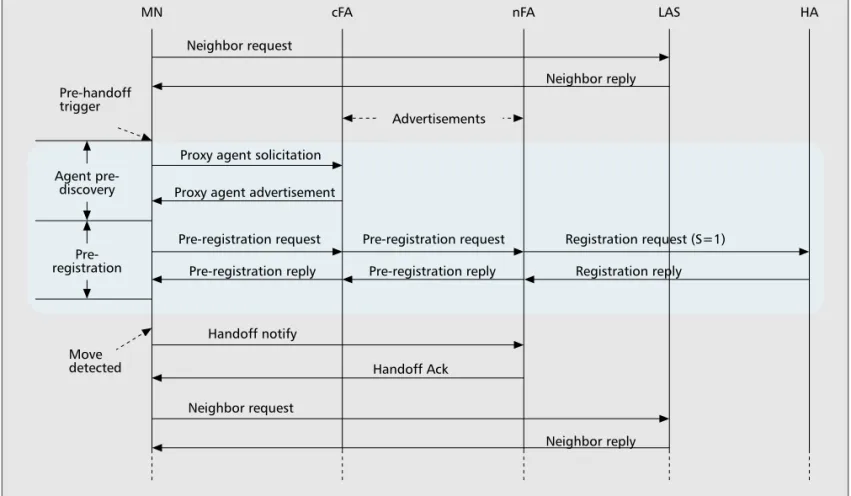
The proposed protocol broadly comprises three phases, neighbor request, agent pre-discovery, and pre-registration (Fig. 3).
Neighboring MAs periodically exchange their advertisements in the proposed design. After an MN has registered successfully in the visited net-work, the MN sends a NeighborRequest to LAS to request topology-related information. The LAS replies to the MN with a NeighborReply, which contains a list of all neighboring APs with their locations and associations with MAs. With this information and MN’s current location plus the direction of movement, the MN can deter-mine the neighbor AP that is most likely to be the next serving AP, and the corresponding nFA on the occurrence of a pre-handoff trigger. The
LAS can be implemented either as a stand-alone server or as an add-on software module in MAs, DHCP Proxies, or RADIUS servers. It is assumed that the information maintained by LAS will be manually configured, since such information rarely changes in most cases.
2This proposal considers
both preregistration and post-registration methods to achieve low-latency handoff. However, this study focuses on the pre-registration case.
YEN LAYOUT 11/17/05 12:08 PM Page 159
MN then starts agent pre-discovery by sending a
ProxyAgentSolicitation to cFA, requesting the nFA’s advertisement. The cFA returns the
requested information via a
ProxyAgentAdvertise-ment.
ProxyAgentSolicitation/Advertisement can be
skipped if NeighborReply also contains the nFA’s advertisement. To this end, the contents of LAS should include advertisements of associ-ated MAs.
An MN obtains its CoA after the agent pre-discovery phase. If the layer-2 handoff is not yet completed, the MN may wait for a post-handoff trigger and then attempt registration. This option eliminates the agent-discovery latency, but not the registration delay.
Alternatively, the MN may directly initiate the registration phase after the agent pre-discovery phase, by encapsulating a Registra-tionRequest that ought to be sent to HA in a
Pre-RegistrationRequest and sending the
Pre-Reg-istrationRequest to the cFA. The cFA then for-wards the Pre-RegistrationRequest to the nFA, where the RegistrationRequest is decapsulated and sent to the HA. When the RegistrationRe-ply sent by the HA is received by the nFA, the
nFA encapsulates it in a Pre-RegistrationReply
and sends the Pre-RegistrationReply to the cFA. The cFA then forwards the Pre-RegistrationRe-ply to the MN.
When the MN receives a post-handoff trigger revealing the completion of a layer-2 handoff, the MN sends a HandoffNotify to inform nFA of its arrival. The MN may then start a new neigh-bor request phase to acquire new topology-relat-ed information.
As in the pre-registration proposal [5], this design has the benefit of allowing a layer-3 hand-off in parallel with a layer-2 handhand-off, significant-ly shortening the overall handoff latency. Moreover, the proposed design allows the com-pletion of a layer-3 handoff even before that of a layer-2 handoff, completely eliminating layer-3 handoff latency.
The HA can start tunneling packets to the
nFA as well as the cFA even before the layer-2
handoff is completed. In MIP, an MN can regis-ter multiple CoAs by setting the S bit (the simul-taneous binding flag) in a RegistrationRequest. The advantage of simultaneous binding is its
bicasting ability. That is, the HA can encapsulate
and send packets simultaneously to all registered CoAs. If this option is enabled in the proposed scheme, the MN can start collecting packets by sending a HandoffNotify to the nFA as soon as the link to the new AP is established.
U
SE OFC
O-
LOCATEDC
OA
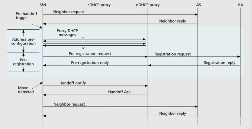
Every subnet is assumed to contain a DHCP proxy. In addition to conventional DHCP func-tionality, the DHCP proxy can allocate a CoA and perform duplicate address detection (DAD) and ßProxy ARP (address resolution protocol) on behalf of a remote MN (an MN not in the current subnet). The DHCP proxy can also encapsulate and decapsulate Pre-Reg-istrationRequest and Pre-RegistrationReply messages, respectively. In this case, LAS keeps AP/DHCP Proxy association rather than AP/MA association.
Figure 4 shows a message flow involving both address pre-configuration and pre-regis-nnn
nFigure 3. Message flow for the FA-CoA case.
Neighbor request
Proxy agent solicitation
Advertisements
Neighbor reply
Proxy agent advertisement
Pre-registration request Pre-registration reply
Pre-registration request Registration request (S=1) Pre-registration reply Registration reply
Handoff Ack Handoff notify Neighbor request Neighbor reply Move detected Agent pre-discovery Pre-handoff trigger
MN cFA nFA LAS HA
Pre-registration
YEN LAYOUT 11/17/05 12:08 PM Page 160
tration. As in the FA-CoA case, an MN sends a NeighborRequest to LAS to request topolo-gy-related information once it has been regis-tered successfully. On the occurrence of a pre-handoff trigger, the MN determines its most probably next serving AP and the corre-sponding DHCP proxy (i.e., nDHCP proxy) based on location information. The MN then starts address pre-configuration by exchanging proxy DHCP messages with the nDHCP proxy. Proxy DHCP messages are similar to regular DHCP messages (Discover, Offer, Request, Ack), but aim to request a valid CoA in the next network domain rather than in the client’s (i.e., the MN’s) current domain.
After an MN acquires its CoA, the MN may request registration after a post-handoff trigger or immediately initiate registration. The pre-registration process is similar to that of the FA-CoA case, except that Pre-RegistrationRequest/
Reply messages are now encapsulated and
decap-sulated at the nDHCP Proxy rather than at nFA. When nDHCP Proxy receives a HandoffNotify sent by the MN, it stops performing Proxy ARP and DAD defense for the MN.
PERFORMANCE
EVALUATION
We conducted experiments to measure handoff delays and lost packets when using CCoAs. In each experiment, either an MN or a correspond-ing node (CN) generated packets at a constant rate (one per 20 ms). The destination of the packets was the MN (CN) if the CN (MN) was the message source. A sequence of packets was lost during the handoff period. The time when the last packet was received before a handoff, and the time when the first packet was received after the handoff, were both recorded. The handoff delay was measured as the time
differ-ence between these two instants. The number of lost packets during the handoff period was also measured.
Figure 5 shows the experimental setup. Dynamics MIP, which was originally developed at Helsinki University of Technology, was used as an MIP implementation. CCoA was assumed to have been used in the MN. The MN was equipped with two identical Intersil prism2-based IEEE 802.11b wireless interfaces, and was located in a place where it could associate with nnn
nFigure 4. Message flow for the CCoA case.
Neighbor request
Proxy-DHCP messages
Pre-registration request
Pre-registration reply Registration reply
Handoff notify Handoff Ack Neighbor request Neighbor reply Neighbor reply Registration request Address pre-configuration Pre-registration Pre-handoff trigger Move detected
MN cDHCP proxy nDHCP proxy LAS HA
nnn
nFigure 5. Experimental setup.
Home agent LAS DHCP proxy 2 DHCP proxy 1 140.113.215.206 140.113.215.0/24 140.113.24.0/24 140.113.89.0/24 140.113.216.0/24 140.113.89.239 Correspondent node
Home IP:140.113.215.207 Home IP:140.113.215.207
MN MN
AP1 AP2
YEN LAYOUT 11/17/05 12:08 PM Page 161
either AP1 or AP2. The steps of the experimen-tal procedure were as follows.
1. Before handoff, associate one of the MN’s interfaces (interface 1) with AP1, and the other (interface 2) with AP2. Configure interface 1 with a CoA through DHCP Proxy 1
2. Start generating and transmitting packets 3. Detach the CoA of interface 1
4. Configure a new CoA for interface 2 through DHCP Proxy 2
5. Perform MIP registration
This procedure only measured layer-3 hand-off delay, and did not consider pre-configuration or pre-registration. Step 3 emulated breaking the link to AP1. Because step 4 was carried out immediately after step 3, no move detection delay occurred. Additionally, this procedure did not consider the erratic layer-2 handoff delay.
The procedure was changed slightly to mea-sure the layer-3 handoff delay with address pre-configuration. A CoA was additionally configured in step 1 for interface 2 through DHCP proxy 2. Step 4 was then skipped. To measure the layer-3 handoff delay using both address pre-configuration and pre-registration, the MN additionally enabled bicasting by per-forming a simultaneous registration for the CoA of interface 2 with the HA in step 1. Steps 4 and 5 were completely skipped, since neither address configuration nor registration was needed. Table 1 summarizes the obtained results, where each value was measured based on ten experimental results.
According to Table 1, the original layer-3 handoff delay was unacceptable for VoIP appli-cations. The handoff delay with address pre-con-figuration was only around 85 ms, which may
still be unacceptable for time-critical applica-tions due to the high variation. Using address pre-configuration plus pre-registration, the hand-off delay dropped further to around 45 ms with low variation. Such results should meet the delay requirement of VoIP applications.
The number of lost packets in each setting generally agreed with the handoff delay. The original MIP incurred a loss of more than 100 packets. This number fell to three packets when using address pre-configuration, and to zero or one with pre-registration.
CONCLUSIONS
We have reviewed several cross-layer techniques that aim to reduce handoff delays in IEEE 802.11/Mobile IP environments. Among these, a post-handoff layer-2 trigger successfully elimi-nates the link-switch detection delay. Conversely, a pre-handoff layer-2 trigger can be used as a signal to execute layer-3 handoff-related activi-ties prior to the associated layer-2 handoff. An MN may use cross-layer topology together with its location and direction of movement to deter-mine the next serving AP and the associated FA or DHCP server to speedup both layer-2 and layer-3 handoffs.
This study has demonstrated how to integrate these techniques in order to reduce the overall handoff delay. The experimental results show that the handoff delay meets the delay requirement of VoIP applications if the MN can first perform both address configuration and registration.
A
CKNOWLEDGMENTThe authors would like to thank the National Science Council of the Republic of China, Tai-n
n n
nTable 1. Means and standard deviations of handoff delay and the number of lost packets with different
settings. Setting Metrics Address configuration + registration Address preconfiguration + registration Address preconfiguration + preregistration
Handoff delay MN sending to CN Avg. 3416 ms Std. 1188.1 Avg. 85 ms Std: 41.7 Avg. 48 ms Std: 23.5 CN sending to MN Avg. 2463 ms Std. 914.2 Avg. 88 ms Std. 39.1 Avg. 43 ms Std. 15.7 Number of lost packets MN sending to CN Avg. 166 Std. 58.6 Avg. 3 Std. 2.1 Avg. 1 Std. 1.2 CN sending to MN Avg. 121 Std. 46.8 Avg. 3 Std. 1.7 Avg. 0 Std. 0.0
Needed layer 2 trigger Post-handoff Pre-handoff, Post-handoff Pre-handoff, Post-handoff Needed location/topology information AP location, MN location, AP location, MN location, AP/DHCP Proxy
association AP/DHCP proxy association
Other technique needed Simultaneous binding
The number of lost packets in each setting generally agreed with the handoff delay. The original MIP incurred a loss of
more than 100 packets. This number
fell to three packets when using address pre-configuration, and to zero or one with pre-registration.
YEN LAYOUT 11/17/05 12:08 PM Page 162
wan, for financially supporting this research under contract nos. NSC 94-2213-E-009 -005 and NSC 94-2219-E-009 -006.
R
EFERENCES[1] M. Shin, A. Mishra, and W. Arbaugh, “Improving the Latency of 802.11 Hand-offs Using Neighbor Graphs,”
ACM Mobisys., 2004.
[2] A. Mishra, M. Shih, and W. Arbaugh, “Context Caching Using Neighbor Graphs for Fast Handoffs in a Wireless Network,” IEEE INFOCOM, 2004.
[3] A. Mishra et al., “Proactive Key Distribution Using Neighbor Graphs,” IEEE Wireless Commun., vol. 11, no. 1, 2004, pp. 26–36.
[4] C.-C. Tseng et al., “Location-based Fast Handoff for 802.11 Networks,” IEEE Commun. Lett., vol. 9, no. 4, 2005, pp. 304–06.
[5] K. El Malki et al., “Low Latency Handoffs in Mobile IPv4,” Internet Draft, Aug. 2005.
[6] H. Fathi and R. Prasad, “Mobility Management for VoIP in 3G Systems: Evaluation of Low-Latency Handoff Schemes,” IEEE Wireless Commun., vol. 12, no. 2, 2005, pp. 96–104.
[7] J. C.-S. Wu et al., “Intelligent Handoff for Mobile Wire-less Internet,” Mobile Networks and Applic., vol. 6, 2001, pp. 67–79.
[8] C. Perkins, “IP Mobility Support,” Tech. Rep. RFC 2002, IETF, Oct. 1996.
[9] A. Mishra, M. Shih, and W. Arbaugh, “An Empirical Analysis of the IEEE 802.11 MAC Layer Handoff Pro-cess,” ACM Comp. Commun. Rev., vol. 33, no. 2, 2003. [10] K. Pahlavan, X. Li, and J.-P. Makela, “Indoor Geoloca-tion Science and Technology,” IEEE Commun. Mag., vol. 40, no. 2, 2002, pp. 112–18.
[11] T. T. Kwon and M. Gerla, “Mobility Management for VoIP Service: Mobile IP vs. SIP,” IEEE Wireless
Com-mun., vol. 9, no. 5, 2002, pp. 66–75.
B
IOGRAPHIESCHIEN-CHAOTSENG([email protected]) is currently a professor in the Department of Computer Science at National Chiao-Tung University, Hsin-Chu, Taiwan. He received his B.S. degree in industrial engineering from National Tsing-Hua University, Hsin-Chu, Taiwan, in 1981; and M.S. and Ph.D. degrees in computer science from Southern Methodist University, Dallas, Texas, in 1986 and 1989, respectively. His research interests include wireless Internet, handover techniques for heterogeneous networks, and mobile computing.
LI-HSINGYEN([email protected]) received his B.S. (1989), M.S. (1991), and Ph.D. (1997) degrees in computer science, all from National Chiao-Tung University, Taiwan. He was an assistant professor (1998–2003) and has been an associate professor since 2003 at the Department of Computer Sci-ence and Information Engineering, Chung Hua University, Taiwan. His current research interests include mobile com-puting, wireless networking, and distributed algorithms. HUNG-HSINCHANG([email protected]) received his B.S. and M.S. degrees in computer science and information engineering from National Chiao-Tung University, Taiwan, R.O.C., in 1990 and 1995. He is currently working toward his Ph.D. degree in computer science and information engi-neering from National Chiao-Tung University. His current research interests include design and analysis of wireless networks, Internet communications, and personal commu-nications networks.
KAI-CHENGHSU([email protected]) received his B.S. degree in computer science and information engineering from National Chiao-Tung University, Taiwan, R.O.C., in 2004 and is currently working toward his M.S. degree in the same department. His research interests include design and analysis of wireless networks, Internet communica-tions, and mobile computing systems.
This study has demonstrated how
to integrate these techniques in order to reduce the overall
handoff delay. The experimental results show that the handoff delay meets
the delay requirement of VoIP
applications if the MN can first perform
both address configuration and
registration.
YEN LAYOUT 11/17/05 12:08 PM Page 163