IEEE TRANSACTIONS ON CIRCUITS AND SYSTEMS—II: EXPRESS BRIEFS, VOL. 52, NO. 3, MARCH 2005 145
CMOS Current-Mode Divider and Its Applications
Weihsing Liu, Shen-Iuan Liu, Senior Member, IEEE, and Shui-Ken Wei
Abstract—Compact, accurate and low-power analog CMOS
cir-cuits for current-mode division and pseudo-exponential function generation are presented, based on a new variable transresistance amplifier. Experimental results of the circuits fabricated in a 0.5- m 2P2M n-well CMOS process show better than 0.3% total harmonic distortion. Measured power is less than 0.22 mW at 100-MHz bandwidth and 1.5-V supply voltages.
Index Terms—Divider, exponential function, transresistance.
I. INTRODUCTION
T
HE ANALOG divider is an important building block in the design of analog signal processing integrated circuits, such as analog computation, fuzzy control, neural network, and analog–digital (A/D) converters and communication systems [1]–[6], etc. However, most of the analog dividers operate in the voltage mode [4], [7]–[9] and only few of them are designed to operate in the current mode [10], [11]. In the past decade, current-mode signal processing has received much attention for their potential advantages such as wide bandwidth, wider dy-namic range, simple circuitry, and lower power consumption [12]. In this brief, a new CMOS current-mode divider is pre-sented. Two different applications are presented to demonstrate the proposed current-mode divider. Experimental results of all the proposed circuits are given to verify the theoretical analysis.II. CIRCUITDESCRIPTION
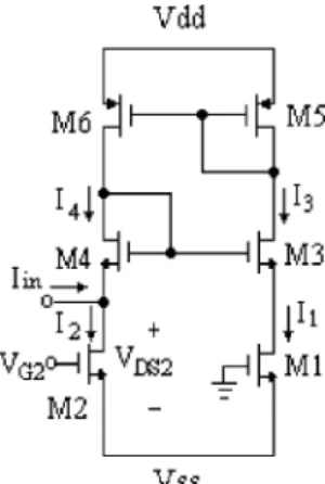
Consider the circuit shown in Fig. 1 [13]. Assume that both M1 and M2 are biased in the triode region without body effect, their drain currents are given by [14]
(1)
(2) where is a bias voltage, are the transconductance pa-rameters and are the threshold voltages of M1 and M2, Manuscript received December 26, 2002; revised October 10, 2004. This work was supported in part by the National Science Council, Taiwan, R.O.C. under Grant NSC 90-2626-E-236-001. This paper was recommended by Asso-ciate Editor G. Cauwenberghs.
W. Liu is with the Department of Electrical Engineering and Graduate In-stitute of Electronics Engineering, National Taiwan University, Taipei 10617, Taiwan, R.O.C., and also with the Faculty of the Department of Electronic En-gineering, Tung Nan Institute of Technology, Taipei 22202, Taiwan, R. O. C. (e-mail: [email protected]).
S.-I. Liu is with the Department of Electrical Engineering and Graduate In-stitute of Electronics Engineering, National Taiwan University, Taipei 10617, Taiwan, R.O.C. (e-mail: [email protected]).
S.-K. Wei is with the Department of Electronic Engineering, Tung Nan Insti-tute of Technology, Taipei 22202, Taiwan, R. O. C.
Digital Object Identifier 10.1109/TCSII.2004.842041
Fig. 1. Proposed voltage-controlled resistor.
respectively. The current mirrors M5 and M6 are used to gen-erate the current and , so that
(3) Assume that M3 and M4 are perfectly matched (i.e.,
and ) and both of them are biased in satura-tion. According to the square-law characteristics of MOSFETs, the following are given [14]:
(4)
Since , it leads to
(5) Because source voltages of M3 and M4 are equal, i.e.,
, therefore the assumption that could be held. Substituting (1), (3), and (5) into (2) and assuming that M1 and M2 are perfectly matched (i.e., and
), is derived as
(6) From (6), a voltage-controlled resistor may be given and its equivalent resistance is given as
(7) According to (7), the equivalent resistance is reversely propor-tional to the bias voltage .
Based on the proposed voltage-controlled resistor, the pro-posed current-mode divider is shown in Fig. 2. Assume that both M7 and M8 are biased in saturation, they can realize a cur-rent-to-voltage converter [15]. Assume that M7 and M8 are
per-fectly matched (i.e., and
) and both of them are embodied in individual wells to avoid the body effect. If the supply voltages , yields
(8) 1057-7130/$20.00 © 2005 IEEE
146 IEEE TRANSACTIONS ON CIRCUITS AND SYSTEMS—II: EXPRESS BRIEFS, VOL. 52, NO. 3, MARCH 2005
Fig. 2. Proposed current-mode divider.
Substituting (8) into (6) yields
(9) According to (9), a current-mode divider would be realized. However, the output voltage of the proposed current-mode di-vider is influenced by the variation of the supply voltage. To keep the proposed current-mode divider work properly, M1 and M2 should be biased in the triode region and other transistors should be in saturation. Since the current must flow into the drain of M2 therefore the gate voltage of M2 should be larger than the ground potential. According to (8), yields
(10) Next, for M2 to operate in the triode region, the output range may be derived as
(11) where is the transconductance of M7 and M8 and is the threshold voltage of M2, respectively.
III. APPLICATIONS
A. Pseudo-Exponential Function Generator
A pseudo-exponential function may be written as [16]
if (12)
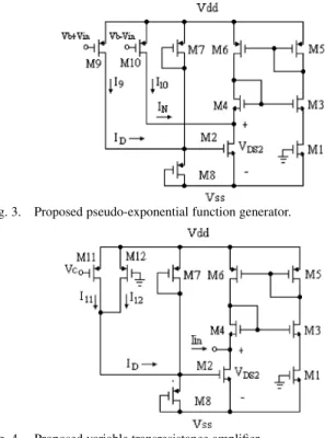
The proposed pseudo-exponential function generator is shown in Fig. 3 [17]. Assume that M9 and M10 are perfectly matched
(i.e., and ) and both
of M9 and M10 are biased in saturation. Based on the square-law characteristics of MOSFETs, the currents and are written as
(13) and
(14) where is the bias voltage. Assume that and
. Substituting (13) and (14) into (9) yields
(15)
Fig. 3. Proposed pseudo-exponential function generator.
Fig. 4. Proposed variable transresistance amplifier. Comparing (15) with (12), results in
if
(16)
where and
. According to (16), a pseudo-exponential function gen-erator may be realized.
B. Variable Transresistance Amplifier
The proposed variable transresistance amplifier is shown in Fig. 4. M11 and M12 realized an exponential function generator [18]. Assume that M11 and M12 are biased in saturation and the transconductance parameters and the threshold voltages of
M11 and M12 are equal (i.e., and
). According to the square-law characteristics of the MOSFETs, the currents and are given as [14]
(17) (18) According to the assumptions and
[18], the current is given as
(19)
where , and
is a control voltage. Substituting (19) into (8) and let the current be the input current yields
(20) Therefore, a variable transresistance amplifier may be realized.
LIU et al.: CMOS CURRENT-MODE DIVIDER AND ITS APPLICATIONS 147
Fig. 5. Die photograph of the proposed current-mode divider.
Fig. 6. Experimental results of the proposed voltage-controlled resistor.
IV. EXPERIMENTALRESULTS
All the proposed circuits have been fabricated in a 0.5- m 2P2M N-well CMOS process. The die photograph of the cur-rent-mode divider is shown in Fig. 5. The threshold voltage for the NMOS is 0.78 V and that for the PMOS is 1.1 V in our process and the transconductance parameters in our process are mA V . All the experiments were per-formed with supply voltages 1.5 V.
Fig. 6 shows the experimental results of the proposed voltage-controlled resistor which were performed with the bias voltages 0.6, 0.8, 1.0, 1.2, and 1.4 V, respectively. As the input current varies from 30 A, the measured equivalent resistors are 18.44 k (at 0.6 V), 13.76 k (at 0.8 V), 10.87 k (at 1.0 V), 9.22 k (at 1.2 V) and 7.85 k (at 1.4 V), respectively, which is consistent with the theoretical analysis calculated by (7).
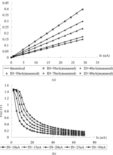
The experimental results of the proposed current-mode di-vider are shown in Fig. 7(a) and (b) which have been performed with , 40, 50, 70, and 80 A while varies from 30 A and 10, 15, 20, 25, and 30 A while varies from 70 A, respectively. The measured output offset voltage is less than 1.5 mV under all situations and the mea-sured maximum linear error is less than 0.85%. The meamea-sured total harmonic distortion (THD) at 100 kHz of the output voltage for 30 A and the amplitude of the current is 0.1, 0.5, and 1 A are 0.03%, 0.122%, and 0.243%, respectively. Also, the measured power consumption is less than 0.22 mW (at 30 A). For the proposed current-mode divider to work properly, the current must be limited by (10) and (11). As the current was increased to 86 A, the corresponding output deviated from its theoretical value [calculated by (9)] by
Fig. 7. Experimental results of the current-mode divider (a)V vs.I (b) V vs.I .
Fig. 8. Frequency response of the proposed current-mode divider.
2.78% (at 30 A). The experimental results are consistent with the theoretical analysis calculated by (9). For measuring the power-supply rejection ratio (PSRR), assume that a ripple was generated along with the supply voltage . If the magnitude of the ripple is 10% of the and the frequency is 100 kHz, the measured PSRR is about 26.67 dB. The frequency response of Fig. 2 is shown in Fig. 8 which was performed with the current 30, 40, and 50 A while the current 20 A and the small-signal current was set to 1% of the current . The cor-responding 3-dB bandwidth are 231, 191, and 179 MHz, re-spectively. Also, the measured input referred noise (at 100 kHz)
148 IEEE TRANSACTIONS ON CIRCUITS AND SYSTEMS—II: EXPRESS BRIEFS, VOL. 52, NO. 3, MARCH 2005
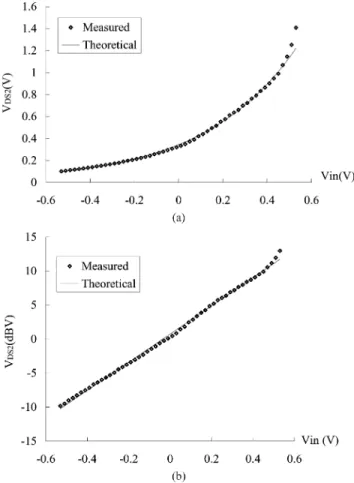
Fig. 9. Experimental results of the proposed pseudo-exponential function generator. (a) Linear scale. (b) Semi-logarithmic (dB) scale.
Fig. 10. Experimental results of the proposed variable transresistance amplifier.
The experimental results of the proposed pseudo-exponential function generator are shown in Fig. 9(a) and (b), respectively. With the bias voltage 0.4 V, as varies from 0.5 to 0.5 V, the output operating range could be more than 20 dB while the linearity error is less than 0.5 dB. The experimental results confirm the theoretical analysis calculated by (16).
Fig. 10 shows the experimental results of the proposed vari-able transresistance amplifier. The experiments were performed with the input currents 1.5, 2.5, and 3.5 A, respectively. As the control voltage varies from to 0.4 V, the tran-sresistance ranges from 90 to 102 dB while the linearity error is less than 1 dB. The experimental results verify the theoret-ical analysis calculated by (20). As a comparison, two different samples were tested using the same procedure, with very sim-ilar results.
V. CONCLUSION
In this brief, a new CMOS current-mode divider is developed. Experimental results have been given to confirm the validity of the theoretical analysis. The proposed current-mode divider can be used to realize a voltage-controlled resistor, a pseudo-expo-nential function generator and a variable transresistance ampli-fier.
REFERENCES
[1] C. Mead and M. Ismail, Analog VLSI Implementation of Neural
Sys-tems. Norwell, MA: Kluwer, 1989.
[2] Nonlinear Circuit Handbook, D. H. Ssheingold, Ed., Analog Devices,
Norwood, MA, 1974.
[3] F. J. Pelayo, I. Rojas, J. Ortega, and A. Priteo, “Current-mode analogue defuzzifier,” Electron. Lett., vol. 29, no. 9, pp. 743–744, 1993. [4] P. Deval, G. Wegmann, and J. Robert, “CMOS pipelined A/D convertor
using current divider,” Electron. Lett., vol. 25, no. 20, pp. 1341–1343, 1989.
[5] U. Singh and M. Green, “Dynamics of high-frequency CMOS di-viders,” in Proc. IEEE Int. Symp. Circuits Systems, vol. 5, May 2002, pp. 421–424.
[6] , “New structures for very high-frequency CMOS clock dividers,” in Proc. IEEE Int. Symp. Circuits Systems, vol. 4, May 2002, pp. 622–625.
[7] D. Ghosh and P. Patranabis, “A simple analog divider having indepen-dent control of sensitivity and design conditions,” IEEE Trans. Instrum.
Meas., vol. 39, no. 3, pp. 522–526, Jun. 1990.
[8] S. I. Liu and C. C. Chang, “CMOS analog divider and four-quadrant multiplierusing pool circuits,” IEEE J. Solid-State Circuits, vol. 30, no. 9, pp. 1025–1029, Sep. 1995.
[9] J. G. Graeme, Operational Amplifier Design and Application. New York: McGraw-Hill, 1971.
[10] H. Wasaki, Y. Horio, and S. Nakamura, “Current multiplier/divider cir-cuit,” Electron. Lett., vol. 27, no. 6, pp. 504–506, 1991.
[11] C. H. J. Mensink and B. Nauta, “CMOS tunable linear current divider,”
Electron. Lett., vol. 32, no. 10, pp. 889–890, 1996.
[12] B. Wilson, “Recent developments in current conveyor and current-mode circuits,” Proc. Inst. Elect. Eng. G, vol. 137, no. 2, pp. 63–77, 1990. [13] W. Liu and S. I. Liu, “CMOS tunable1=x circuit and its applications,”
IEICE Trans. Fund., vol. E-86A, pp. 1896–1899, Jul. 2003.
[14] N. R. Malik, Electronic Circuits. Englewoood Cliffs, NJ: Prentice-Hall, 1995.
[15] K. Bult and H. Wallinga, “A class of analog CMOS circuits based on the square law characteristics of an MOS transistor in saturation,” IEEE J.
Solid-State Circuits, vol. SC-22, pp. 357–365, Jun. 1987.
[16] A. Motamed, C. Hwang, and M. Ismail, “CMOS exponential current-to-voltage converter,” Electron. Lett., vol. 33, no. 12, pp. 998–1000, 1997. [17] W. Liu and S. I. Liu, “CMOS exponential function generator,” Electron.
Lett., vol. 39, pp. 1–2, Jan. 2003.
[18] C. C. Chang and S. I. Liu, “Pseudo-exponential function using MOS-FETs in saturation,” IEEE Trans. Circuits Systems II, Analog Digit.