QoS-Guaranteed Polling-Based 2-Layer Integrated Multihop
Scheduling Algorithm for Wireless Ad Hoc Networks
Chih-Cheng Tseng*
Graduate Institute of Communication Engineering. National Taiwan University,
Taipei, Taiwan, R.O.C. [email protected]
Absnaec-ln this paper, with removing the global synchronization that are usually assumed, we use the concept of relative timing between neighboring clusters and the concept of rendezvous windows for the gateway nodes to rendezvous with its connected clusters for timing conversion to overcome the synchronization problem in wireless multihop ad hoc networks. To be able to schedule both intra-cluster and inter-cluster traffic sources in the assumed 2-layer network hierarchy, we propose a
QoS-guaranteed polling-based 2-layer integrated multihop scheduling algorithm that schedules both intra-cluster and inter- cluster packets based on a preset service priority. The delay and jitter for intra-cluster and inter-cluster connections are analyzed and are used as the admission criterion for connection setup requests.
Keywordsod hoc networks, cortneecivity. power conservation
1. INTRODUCTION
In the recent years, the topic of wireless ad hoc networks has received increasing attention e.g. [l]. A wireless multihop
ad hoc network is a wireless network without existence of fixed infrastructures. As a consequence, delivering QoS guaranteed multimedia traffic sources over the multihop wireless ad hoc networks
are
much more complex than that in conventional communication networks. The key design issues to support QoS guaranteed multimedia services in the multihop ad hoc networks are network architecture, rendezvous window, synchronization and multihop scheduling. The network architecture of wireless ad hoc network is generally regarded asflat or hierarchical. In the flat network architecture, nodes are assumed to have the same capabilities and peer-to-peer communications are used. In the hierarchical architecture, the entire network is organized into set of clusters. Each cluster is controlled by a clusterhead (CH) and clusters are connected by gateways (GW). Links connect CHs and GWs constitute a virtual backbone. Nodes that are neither CH nor GW are regarded as ordinary nodes. In the wireless multihop ad hoc networks, regardless the network architecture, packets are basically multihopped to the intended receivers. To provide QoS guaranteed multimedia services, a multihop scheduler is thus necessary to schedule packets to (from) the downstream (upstream) nodes. In other words, an admitted packet must he fotwarded to the next hop before the required QoS provisions are violated. This requires GW to schedule rendezvous window with neighboring clusters at the right time and last for a sufficient period of time to satisfy the required QoS provisions.
'C-C Tseng is also with the Dcpamneni of Electronic Engineering, Jin- Wen lnSiiNie ofTechnology, Xin-Dim, Taiwan, R. 0. C..
Kwang-Cheng Chen
Graduate Institute of Communication Engineering, National Taiwan University,
Taipei, Taiwan, R.O.C. [email protected]
To achieve this, certain degree of network synchronization is needed. However, without the help of infrastructure, there is no centralized timing source to synchronize the entire wireless multihop ad hoc network. This paper addresses the above issues and proposes a 2-layer integrated QoS guaranteed multihop scheduling algorithm as the solution in designing QoS-guaranteed wireless multihop ad hoc networks. The rest of the paper is organized as follows. In Section 11, the related assumptions and models are presented. Section III discusses the proposed algorithm and Section IV provides the related QoS analysis and Section V presents the initial connection setup procedure and admission control. Section VI concludes this paper.
11. OPTIMUM TRANSMISSION RANGE ANDNETWORK CONNECTEDNESS
A . Basic Assumptions
The wireless multihop ad hoc network is assumed to he connected, and a topology control scheme e.g. [Z] is used to maintains the connectedness of the network. There also exists an underlying ad hoc routing protocol to provide routing information from the source node to the destination node. The wireless multihop ad hoc network is organized into a hierarchical architecture with set of clusters by a clustering algorithm e.g. in [3], the resulting cluster architecture possesses minimum number of orphan clusters, and thus, the total number of generated clusters is minimized. In this clustered wireless multihop ad hoc network, nodes are classified into CH, GW and ordinary nodes and all communications are required to go through the CH even though the source node and the destination node are directly connected.
B. Trafjc Model-
stated below. 1.
The characteristics of the
traffic sources
we considered are A CBR source iis
modeled by (rc,r, j , ),
where re.! is the average rate and j, is the maximum tolerable jitter. Each CBR packet generated from an admitted CBR source is temporally stored in its Ready-To-Transmit (RTT) buffer. The jitter is defined as the difference between the instant that two consecutive packets departing from the RTT buffer and the instant that two consecutive packetsarriving at the RTT buffer. Besides, all inter-cluster connection in this paper are assumed to be CBR sources. A VBR source i is modeled by (I; ,.,, b , , d j ) , where
r,!
is the average rate, b, is the maximum burstiness and d, isthe maximum tolerable delay. The first two parameters are obtained by regulating the i-th VBR source through a (bj,<.,!) -leaky bucket where I;.,( is the token generation rate and br is the token buffer size. Each VBR packet output from the leaky bucket is also temporally stored in a RTT buffer. Another VBR regulation technique proposed in [4] and [SI is to locate the leaky bucket at the CH. However, since CH has no knowledge about the arrival process of the VBR source, an extra separated signaling channel or extra state transition is needed to obtain the VBR arrival process. The delay of a VBR packet is defined as the difference between the instant that it arrives at the CH and the instant that it arrives at the RTT buffer. An ABR source is considered as a Poisson process. The ABR sources have neither jitter constraint nor delay constraint. ABR sources share fairly and efficiently the remaining bandwidth of the inter-cluster connections, CBR and VBR sources. Besides, all connection request packets are also regarded as ABRpackets.
C. The System Mode/
The system is modeled as follows. In the clustered network hierarchy, each CH is categorized into Home CH (HCH), Visiting CH (VCH) or Destination CH (DCH). The HCH is the CH of the cluster where a connection is originated, The DCH is the CH of the cluster where the connection is terminated. In addition to HCH and DCH, the CHs that a connection traverses are regarded as VCHs. There are two types of polling tokens (PT) in the system: inter-cluster PT and intra-cluster PT. The inter-cluster PT consists of Home Token (HT), Remote Token (RT) and Virtual Token (VT). All HTs and RTs are further classified into incoming PTs (1-HT and I-RT) and outgoing PTs (0-HT and 0-RT). The 1-HT is located at the HCH and is used to represent an inter-cluster packet at the source node. The 0-HT is also located at the HCH but it represents an outgoing inter-cluster packet at the HCH is ready to he forwarded to the downstream GW. The RT can be located at the GW, VCH or DCH. An I-RT located at the VCH or DCH represents an
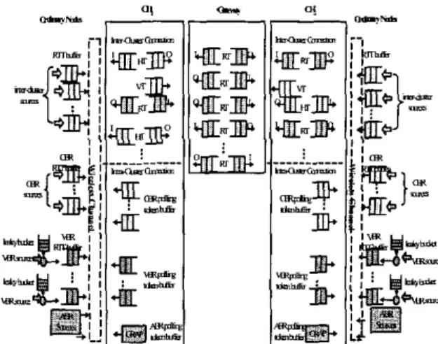
incoming inter-cluster packet at the upstream GW. An 0-RT located at the VCH or DCH represents an outgoing inter-cluster packet is ready to be forwarded to the downstream GW or destination node respectively. An I-RT located at the GW represents the GW is ready to receive an inter-cluster packet at the upstream HCH or VCH. An 0-RT in the GW represents the GW is ready to forward an inter-cluster packet to the next downstream VCH or DCH. VT only locates in the CH and represents the GW that the VT directed is busy in servicing a connection that does no traverse the CH. The intra-cluster PTs consist of PTs for CBR VBR and ABR sources. We assume that the channel access priority of inter-cluster PTs prevail over the intra-cluster PTs and among the inter-cluster PTs, incoming PTs are with higher priority than outgoing PTs. As to the intra- cluster PTs, the CBR PTs are with the highest priority then the VBR PTs and the ABR sources are with the lowest priority. An example of the system model for two clusters connected by a G W is illustrated in Figure 1. In this figure, there are two inter- cluster connections originating from Clusterl and terminated at Cluster2, one inter-cluster connection originating from Cluster2 2.
3.
Figure I An example of the system model with two clusters connected by a
GW.
and terminated at Clusterl and one inter-cluster connection that passing through the GW to
a
cluster other than Clusterl and Cluster2. The two HT PT buffers in CHI and two RT PT buffers in CH2, one RT PT buffer in CH, and one HT PT buffers in CH2 and one VT PT buffer in both CHI and CHI are the PT buffers corresponding to the inter-cluster connections.111. Z-LAYER INTEGRATED QoS-GUARANTEED MULTIHOP SCHEDULING ALGORITHM
Based on the flat network architecture and the global synchronization assumptions, scheduling packets traverse the wireless multihop ad hoc networks are generally classified into node scheduling [6] and link scheduling [7]. The main objective of these two scheduling schemes is to find
a
conflict- free schedule that maximizes the system throughput. However, in [6] the problem of determining transmission schedules with optimal throughput is shown to be NP-conlplete. In the flat network architecture, the available network bandwidth is highly depends on the frequency of network topology dynamics since any network topology update must be distributed to all nodes in the network. Besides, the global synchronization assumption requires each node to synchronize with a fixed absolute timing source that is not realistic in network without the infrashucture such as wireless multihop ad hoc network. In this paper, with clustering assumption, the available network bandwidth is increased since the local network topology updates need only be forwarded to the local CHs. Furthermore, the global synchronization issue can be reduced to the intra-cluster and the inter-cluster synchronization problems. For the intra-cluster synchronization, all nodes in the cluster follow the CH timing. For the inter-cluster synchronization, the relative timing or the timing offset between the connected clusters is used for GW to forward packet between clusters.For the 2-layer clustered network architecture, the general design approach of a multihop scheduling algorithm is to design two schedulers to schedule intra-cluster and inter-cluster communications individually. In the following, we present a novel 2-layer integrated multihop scheduling algorithm that can both schedule intra-cluster and inter-cluster communications.
The following algorithm is executed at each CH to schedule QoS guaranteed packets according to the preset priority.
Pmcedure C!uslerhaad(
Generates PT of e& admitted connection based on the required average rate;
While (CH senses the channel idle)(
selecls the pendin PT (excluding the VTs) with the highest pnonty:
If (an I HT is foun&
polls the corresponding source node to Send a packet; remover the 1-HT from the PT buffer:)
If (an 0 HT is found)( I',uTu=="cuI,
~. .
polls the6&hatian node
sends the packet to the d&tination node: removes the O_HT from the PT buffer:) ~
if (a Hello Dacket from 1 the downtream G W nede 1s received)(
p l l s and Sends a acket to the downstream GW node:
removesfhe 0 H f fmm the PT buffer at the CH:
removes the &responding 1-RT from the PT buffer at the downstream GW node;)))
If (an 1-RT isfound)(
polls the upslieam GW ncde to Send a packet: removes the I RT from the PT buffer at the CH:
removes the-wnesoondino 0 RT fmm the PT buffer at the
If (a Hello packet from the upstream GW node is received)(
upstream GW node;)j
polls the deStinatiOn node:
Sends the packet lo the destination node; removes the 0-HT from the PT buffer at the CH:)
if (a Hello packet fmm Ihe downstream G W node is received)(
I f ( a n 0 RTirfoundX
If (VCH==DCH)(
else(
polls the downstream GW ncde 10 receive a packet: removesthe0 RTfmmIhePTbufferaltheCH:
remoy$s Ihe 1-RT from the PT buffer at the downstream GW ncae;i>>
If (a CBR token IS foundXpollr the wrresponding CBR source Io send a
If (a VBR loken is found)(polls the COmSpOnding VRB source 10 send a
packer
removks the token form the corresponding P T buffer:] if (the corresponding RTT packet: buffer is not empty)
the VBR source Sends DUI a packet:
The following algorithm is executed at each GW to rendezvous with clusters.
Pmcedure Gateway()(
While (the channel corresponds to the highest ptiotity P T is sensed idle)(
If(thisPTis I RTarO-RT)
SlSB
sends a Kello packel lo the corresponding CH to signal ils appearance takes hrm Io rendezvous With all the connecled CHs:))
(or return) fmm other C H
IV. QOS ANALYSIS
In this section, based on the analyses in [9], we provide the mathematical analyses of the packet delay and delay jilter at each CH and GW along the path of an admitted connection. Let
rL,n
= T ~ , ,+rFds,
he the time to send a packet at the first and last hop, i.e. from the source node to the HCH and from theDCH to the destination node respectively,
rb,n
= roihe,+
r,,,,
+
~ 2 , ~
be the packet transmission time at the remaining hops of the considered path wherecoBe,
is the offset time from the instant that a CH wants to forward a packet to a GW to the instant that the CH receives a Hello packet from the GW. We further classify the PTs into four classes. Those I-HT at the HCH and 0-RT at the DCH are Class 1 PTs. Ignoring all lower priority VTs in the same CH that direct to different GW, those 0-HT and 0-RT that are followed by a VT or an I-RT that directs to the same GW are Class 2 PTs. According to the definition of VT, when determining the delay/jitter of a specific PT, VTs that satisfy one of the following two conditions are ignored: (i)lf a Class 1 PT is considered, all consecutive higher priority VTs between this Class 1 PT and the last higher priority 0-HT or 0-RT are ignored. (ii)If an I-RT is considered, all higher priority consecutive VTs between this I-RT and the last 0-HT or 0-RT that direct to different GWs are ignored.As
a result, those VTs that are actually considered are regarded as Class 3 PTs. The rest of PTs are Class 4.Weassume for each considered PT, the number of higher priority Class I , Class 2, Class 3 and Class 4 PTs are h , , h2, h, and h4 respectively. For the intra-cluster communications, we assume there are totally Nc CBR sources and NV VBR sources.
Lemma 1: Let V be the total bandwidth consumed by all higher priority PTs than the considered I-HT in the HCH or 0-RT in the DCH, i.e. Class I PT. The delay of a Class 1 I-HT in the HCH (i.e. the first hop), d f ' , of connection c is
(1)
I < / < h , T ~ , ~ + ( 2 h , + h , + l f r * , ~
I-v
Also, the delay
of
a Class 1 O R T at the DCH (i.e. the last4
- hop), d:',
of connection c is ( 2 ),',
< 4 d ~ + + ( 2 h 2 + h , + l ) r , ,
I-v dD-
where 4 hv
= ~ r , ! " r ~ o , e + ( 2 C r : ' + C r F ' ) r , , a . (3)"I=/ ",=I *=I
Proof To show d;'
,
we assume a marked Class 1 I-HT is generated at time 0. Consider the case that on arriving of the marked I-HT, HCH is transmitting a packet. In this case, the marked 1-HT at most must to wait T , , ~ , ~ for this packet to complete its transmission. After that, according to the preset service priority, the marked I-HT still have to wait for sewice until all higher priority PTs are depleted. Since the inter-cluster packet transmission at the first hop and the last hop is equivalent to an inma-cluster packet transmission, there is no Class 3 PT. The number of higher priority Class I , Class 2, and Class 4 PTs generated in d r ) are upper bounded by x : = , [ r P f ' 1 >2ch
" 8 4 [ r ; ' d f ' l,
andC"
",=I [ r / ' d f ' l respectively. Note that the number of higher priority Class 2 PT is doubled. According to the proposed algorithm, the next lower priority VT or 1-RT to this Class 2 PT will receive service only when a Hello packet from a GW is received. Since the Class 2 PT generates two PTs, I-RT and 0-RT,in
the GW, the GW will send a Hello packet to the CH for the next lower priority VT or I-RT to this Class 2 PT after the two PTs are services. Thus, the equivalent number of PT of a Class 2 PT is doubled. Therefore, the delay boundfor
this marked I H T isd?'
sr,,
+ c : = , r r : ' d : ' l d , o(4)
+(2Ch
",=I [r:ld;'l+
c"
*=I [ r ~ ' d ~ ' l ) T * , o . Using the fact x + l , w e havewhere Vis defined as in (3). Following the same derivations,
( 2 ) can be obtained. Q.E.D.
Lemma 2: Let W be the total bandwidth consumed by all PTs with higher priority than a marked PT at the CH of the n-th hop of connection c, the delay of the marked PT is
( 5 ) cl
<
4 r k
+@h, +2h, +A4+I).r,,o
di-
I-w h, wherew
= Y+
2C
r$Irdma.(6)
m=,Proof Assume the marked PT is generated at time 0. Consider the case that on arriving of this marked PT, the CH is
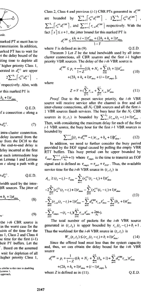
Figure 2 Two E I U S ~ C ~ S connected by a gateway node.
transmitting a packet. In this case, the marked PT at most has to wait for
rdo,a
for the CH to finish this transmission. in addition, according to the service priority, the marked PT has to wait for depletion of all higher priority PTs. Let the delay bound of the marked PT d y be the maximum waiting time to deplete all higher priority tokens. The number of higher priority Class I , Class 2, Class 3 and Class 4 PTs generated in dFi are upper bounded byc?.,[?:'dF1l
,
2 1 " "4 [r;)df'],
2Ch'
"A [,.131d;l1
and x:=.,[r:'dF'l' respectively. Also, with the fact [ x i < x + I,
the delay hound for this marked PT isdr' 5
4 d
+W,
+2h, +h,+l)rda,o
I-W
Theorem 1 The end-to-end delay of a connection c along a where W is defined as in (6).
path with g' hops to the destination is
Q.E.D.
9-1
d:':," =dFl+cdf)+dl'l D ' (7)
"4
Proof For g=2, it is basically an intra-cluster connection. The end-to-end delay is equal to the delay incurred from the source node to the HCH and the delay from the DCH to the destination4. As stated in Lemma 1, the end-to-end delay is
df'+dg'. For g>2, in addition to the delay incurred at the first and the last hops, the delay i n c w e d at each intermediate hop should also be included.
Thus,
based on Lemma 1 and Lemma2,
the end-to-end delay of a connection c along a path with ghops to the destination is
d:;ig = dF1
+E
d f l +d<" D 'Theorem 2 Let Y be the total bandwidth used by the inter- cluster connections and the first i-l CBR sources. The jitter of the i-rh intra-cluster CBR source is
I-1 Q.E.D. "=i d,FBR S ( h , + i - 1 ) r ; , " + ( 2 4 + h ~ + l ) f ~ ~ , ~ I - Y %
(8)
where 6-,Y=V+CV~,,,~L,~.
(9) "?=IProof: Assume a marked PT of the i-rh CBR source is generated at time 0. The waiting time in the worst case for the marked PT to access the channel consists of the time for the channel to he idle, the time for all Class 1, Class 2 and Class 4 PTs to deplete their PT buffers and the time for the first (i-I) higher priority CBR PTs to deplete their PT buffers. Let the jiner bound of the marked PT be d,"", Based
on
the assumed service priority, the marked PT has to wait for depletion of all higher priority PTs. The number of higher priority Class 1,The rearan for daubling the number ofClais 3 PT i s similar Io the case in doubling
IhenvmbcrorClariZ PTdircurred mrhe&m"ofLemma I
g is an even nunher due to the CH-GW forxardinp ammach. In thlr case. Ihe HCH is cpuivalenl Io the DCH.
'
'
Class 2, Class 4 and previous (i-1) CBR PTs generated in d:" are bounded by c",,rrfd:BR1 , 2ch2 ",=I [r;'dcBR
,
1
'e"
I*=,r r j " d y ] ,
andc-l,[vc,d:"l
respectively. With thefact
r.15
x + I,
the jitter bound for this marked PT isd,c8a
(4
+ i-
+ (2h, + h, + l)r,+,,o 1-Ywhere Y is defined as in (9).
Theorem 3 Let 2 he the total bandwidth used by all inter- cluster connections, all CBR sources and the fnst i-l higher priority VBR sources. The delay of the i-rh VBR source is
Q.E.D.
... .
Proof Due to the preset service priority, the i-rh VBR source will receive service after the channel is free and all inter-cluster connections, all Nc CBR sources and all the first i- 1 VBR sources finish services. The busy hour for the Nc CBR
sources in
( r l , r 2 )
is bounded byc ~ , ( ~ ' , ~ ( r * - ~ , ) + l ) r ~ , "
.
Then, with considering the maximum delay for each of the firsti - l VBR source, the busy hour for the first i-l VBR sources is hounded by
CIL,[(t,+C" - r L + b n , + 0 L . (12) In addition, we need to further consider the busy period provided by the EOF signal caused by polling the empty VBR RTT buffers. This busy period can be upper bounded by r m n m c " , ( y + l ) where
rempn
is the time to transmit an EOF signal and is defined asrvnyn
= rP8[+rEoF.
Thus, the available service time for the i-rh VBR source in(r,
, r 2 )
ish
A%.., ~ ( t , -rl)-rh,s
-Ck!"(t,
- r l ) + 1 ) L-2EP(r2 -rl)+l)rda,e
-CtC'(r,
-II)+l)r*,a
-z(r.,O,
- t , ) +Ork
- ~ d ? r v . m r k a - c ( b m+OLO
-Crmp.
-(r2 -t,)(Cr,,.rhn
++I.
m=, h h. (13) m=! m=, NC i-/ ,-I ",=I m-1 ",il i-l ,-I ",=, "7=,The total number of packets for the i-rh
V B R
source generated in(r,,r2)
is upper hounded by r ,,,,(ri
-r,)+b, + I.
Thus the workload for thei-rh
VBR source in(r,,r2)
isK.,,
(I, J, 5 (rV.((t2-
1, ) + b,+
(14) Since the offered load must less than the system capacity and, thus, we can obtain the delay hound for thei-rh
VBR source d y = p , + - ( ( 4 + ~ ~ + z ( b ~ + l ) + C d ? ~ " , ~ ) ~ L , ~ i-l 1-1 1 1-2 m=, I = ,+W
+A, +(i-l)%qn)9 whereZisdefinedasin(l1). Q.E.D. !147G” CH; I F l l . 5 ,
RT-il.4,
7
,.li)nm “ d r , IbiThi~mnandmd~”~nN.oil.g,o*M
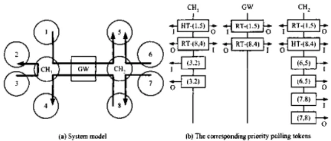
Figure 3 Intrasluster and intcr-chstcr connection in the network shown in Fimurc 2 and thc corresponding PTs at CHs and GW.
TABLE I THE END-TO-EHD DELAY AND DELAY SUFFERED AT EACH HOP.
V. INITIAL CONNECTION S E N P AND ADMISSION CONTROL
In this section, we present procedures to establish a new connection. As assumed Section II, all connection setup request (REQ) packets are regarded as ABR packets, i.e. the request packets can only access the channel when no pending higher priority token is found. As a CH receives a REQ packet, it determines if the requested QoS provisions can be honored based on Lemma I , Lemma 2, Theorem 1, Theorem 2 and Theorem 3. Consider to setup an intra-cluster connection in the wireless multihop ad hoc network as depicted in Figure 2. Assume node 1 tries to establish an intra-cluster connection lo node 2. Node 1 follows the GRAP protocol to send a REQ packet containing the required QoS provisions to CH,. CH, lwks up the routing table and recognizes the requested connection as an intra-cluster connection and, then, calculates the available bandwidth to decide if admits the request. If CH, admits the request, the connection is setup and the required bandwidth is reserved. To setup an inter-cluster connection, a source node must first send out a REQ packet containing the required QoS provisions to the associated HCH. After receiving this REQ packet, the HCH based
on
Lemma 1, Lemma 2, Theorem 1, Theorem 2 and Theorem 3 to determine if the required QoS provisions can be met. If not, it rejects the request. Otherwise, it appends the calculated delay/jitter to the REQ packet and forwards this REQ packet to the downstream GW. The REQ packet is then fonvarded to the VCH. Also, theVCH calculates and checks if it can honor the requested QoS provisions. The procedure repeats until the REQ packet reaches the DCH. If the DCH can also guarantee the requested QoS provisions, a reply (RPY) packet will be sent hop-by-hop back to the source node and the connection is established. AAer the connection is setup, the corresponding PTs described in Section II-C are generated at each CH and GW that the connection traverses. The entire network can be modeled like Figure I . Note that forwarding the REQ and RPY packets can be simplified by piggybacking them into the general packet transmissions.
The system model and priority of PTs for an example of three intra-cluster connections (3,2), (6,s) and (7,s) and two inter-cluster connections (1,5) and (8,4) established in the wireless ad hoc network as shown in Figure
2
are shown in Figure 3. We assume the link speed is IOMbps, the packet size is 1K bits, and the polling signal, EOF signal and the Hello packet are all SO hits. Therefore, we have zwck,=O.lmsec, Ip#zE,,~rH,ii,=Spsec. For simplicity, we let cwcki=l and normalize every parameter with respect to
zwCb,,
i.e., rp0,,=r~of=z~,,~=b,,~=O.O5,
rd0,0=2.2, ronc,=l.l,
~,T; =1.05 and&,?=O. 1. Assume there are three intra-cluster connections (3,2), (6,5) and (7,8) and two inter-cluster connections (1,5) and (8,4) established in the wireless multihop ad hoc network with two CHs connected by a GW. The corresponding system model and the priority of polling token for each connection are shown in Figure 3(a) and Figure 3(b). For each VBR source, we assume the parameter pr=O.ld,,,.The theoretical jitter and delay suffered in each hop and the end-to-end delay for each connection are listed in TABLE I. By verifying the calculated delayijitter and the end-to-end delay, we find that the requested QoS provisions of all admitted connections are guaranteed and the requested connections a re established.
VI. CONCLUSIONS
In this paper, without the global synchronization assumption that are usually made, we use the concept of relative timing between neighboring clusters and the concept of rendezvous windows for the GWs to rendezvous with its connected clusters for timing conversion to overcome the synchronization problem in wireless multihop ad hoc networks. To he able to schedule both intra-cluster and inter-cluster traffic sources, we propose a QoS-guaranteed polling-based 2-layer integrated multihop scheduling algorithm that schedules both intra-cluster and inter-cluster packets based on a preset service priority. We provide the end-to-end delay bound for inter- cluster connection, delay bound for VBR source and jitter bound for CBR source and these delay bounds are used as the criterion of admission control in order to achieve guaranteed
QoS services.
REFERENCES
[I1 J. Haartscn, “The Bluetwth Radio System,” IEEE Personal Mo~azine, pp.28-36, Feb. 2000.
[2l [3]
C.C. Tseng and K.C. Chen, “Power Efficient Topology Contml in Wireles Ad Hoc network^," IEEE WCNC2004 (Accepted).
C.C. Tseng and K.C. Chcn, “A Novcl Distributcd BoundayFint Cluster-Minimized Clustering Algorithm far Wireless Ad Hoe Networks,” Submined to IEEE PIMRC2004.
D. M. Zhao, X. M. She” and J W. Mark, “Efficient Call Admission
Control for Heterogeneous Servica in Wireless Mobile ATM Networks,” IEEE Comminicorlons Magzine, October 2000.
2. R. Chang, 1. H . Lee, C. C. Chmg, C. H. Li, and B. L. Sui, “A Novel Scheme Using thc Information of Departure Processes for Delay Guarantees of Distributed VBR Traffic,” IEEE/ACM Trans. on
Newroking, vol. 9, no. 4, A u g e ~ t 2 0 0 1 .
A. Ephremides and T, V. Troung, “Scheduling Broadcasts in Multihop RadioNetwork.”lEEE Trans. Comm., vol. 38, pp. 456-460, Apd 1990. D. J. Baker and A. Ephremides, “The Architecture Organization of a Mobile Radio Nchvork via a Distributed Algonlhm,” IEEE Tmions.
Comm.. vol. C O M - 2 9 , ~ . 16941701, Nov. 1981. [4]
[5]
[ 6 ]
[7]
[SI ICC. Chen and C.H. Lee. “Group Randomly Addressed Polling for Wircless Dam Networks”1EEEICC ‘94.
191 C.C. Tseng snd K C. Chen, “Prioriry Polling with Reservation Wireless Accas Rotocol for Multimedia Ad Hoc Nehwrks,” IEEE WC 2002