An electrically tunable depth-of-field endoscope using
a liquid crystal lens as an active focusing element.
Hung-Shan Chen, Ming-Syuan Chen and Yi-Hsin Lin*
Department of Photonics, National Chiao Tung University, 1001 Ta Hsueh Rd., Hsinchu 30010,
Taiwan
*
Corresponding author: [email protected]
ABSTRACT
An electrically tunable depth-of-field (DOF) endoscope using a liquid crystal lens (LC lens) as an active focusing element is demonstrated. The optical mechanism of the electrically-tunable DOF endoscope adopting a two-mode switching LC lens is introduced. The two-mode switching LC lens provides not only a positive lens power but also a negative lens power. Therefore, we could extend the range of DOF originally from 27 mm ~ 55 mm to 12.4 mm ~ 76.4 mm by using the two-mode switching LC lens as an active focusing element. The detail derivations of the optical mechanism of the endoscopic system adopting a LC lens are invistgated. The more detail experimental results are demonstrated. We believe this study can provide a more detail understanding of an endoscopic system adopting a tunable focusing lens.
Keywords: Liquid Crystal Lens, Endoscope, Depth of field, DOF
1. INTRODUCTION
The conventional endoscope can be classified into 3 types: capsule type, flexible type, and rigid type. [1] All of the endoscopes suffer from limitation of depth-of-field (DOF) and a fixedobjective distance. In order to extend the DOF for practical uses under a throat or a stomach diagnosis, the conventional camera system or the conventional image system adopting the mechanical movement of lens modules have the problems of large lens displacement and large diameter of the lens module.[1] In 2011, S. Kuiper proposed a tunable focusing electrowetting-based liquid lens for endoscope.[2] Although the focusing properties of the liquid lens were introduced, the discussions of the depth of field of the endoscope were not discussed. In addition, the liquid lens also had the disadvantages of fragile, unavoidable interfacial reflection, and large power consumption owing to the DC-voltage operation.[3-6] Recently, we introduced an endoscopic system adopting a liquid crystal lens with an electrically tunable depth-of-field.[7]. The LC lens operated as a positive
lens and a negative lens can help to extend the DOF of the endoscopic system. However, the detail derivations still need to address. In this paper, the detail derivations of the optical mechanism of the endoscopic system adopting a LC lens are investigated. The spatial resolutions of the object and more detail experimental results are demonstrated. We believe this study can provide a more detail understanding of an endoscopic system adopting a tunable focusing lens.
2. OPERATING PRINCIPLES
The structure of the endoscopic system using a LC lens is illustrated in Fig. 1(a). As shown in Fig. 1(a), the system consists of a polarizer, a LC lens, an image sensor, an image lens and light emitting diodes (LEDs). The transmissive axis of the polarizer is parallel to the optical axis of the LC lens. The image lens is a lens module with a group of plastic lenses, and the image lens is viewed as an equivalent thin lens with a diameter of Ds. Fig. 1(b) shows the equivalent optical system of Fig. 1(a). According to the Geometrical Optics, the electrically-tunable objective distance (u(V)) which is the distance between the object and the LC lens can be expressed as:[7, 8, 9]
, ) ( 1 ) ( sys LC V P P V u + =
(1)
where V is the applied voltage on LC lens, PLC(V) is the lens power of LC lens. The lens power is an inverse of the focal length.
T
he Psys is the lens power of imaging lens system. The Psys can be written as:2 1 1 1 1 d d s P n sys P − + − =
. (2)
where d1 is the distance between the LC lens and the imaging lens which approximately equals to the thickness of the glass substrate. n is the refractive index of the glass substrate, Ps is the lens power of the imaging lens, and d2 is the distance between the imaging lens and the imaging sensor. The DOF is a distance range (δ) of the objective distance in which the contrast of the image on the image sensor is acceptable.
Liquid crystal lens
d
2d
1u
Entrance pupilq
Ds’ DLC Ds Blur B δfar δnear δu-q
Imaging lens Image sensor δLiquid crystal lens
Imaging lens Polarizer Image sensor LED light
(a)
(b)
Fig. 1 (a)The structure of the endoscopic system adopting a LC lens. (b) The equivalent optical system of (a).
To derive DOF of the endoscopic system, we have two steps to follow. The first step is to define the entrance pupil of the endoscope system. The entrance pupil is the image of the aperture stop in object space. The entrance pupil of the endoscopic system has the smallest extension angle from the object to the entrance pupil.[9] In our endoscopic system, we have the LC lens with a diameter of DLC and the imaging lens with a diameter of Ds. The entrance pupil with a diameter of Ds’ is the image of the imaging lens formed by the LC lens and the entrance pupil is in front of the LC lens with a distance q, as shown in Fig. 1. We will demonstrate the chosen of entrance pupil in this step. DLC is 2mm. The diameter of Ds’ is q×Ds×n d1, whereq=1(PLC(V)−n d1). Since the lens power of the LC lens in our system is in a range between -12.5D (Diopter or m-1) and 19.9D, the lens power of the LC lens also limits the range of q between 1.263mm and 1.282mm and the range of Ds’ between 1.263mm and 1.282mm.[9] As a result, we can decide the entrance pupil by choosing the smallest extension angle of the two optical components. The relations for the extension angle of the LC lens (θLC), and the extension angle of the image of the imaging lens (θs’) are
) ( tan 1 u DLC LC − = θ and ' tan1( ' ) q u Ds s − = −
θ
, respectively. By putting the experimental parameters into the relations of θLC and θs’, we found that θs’ is always the smallest one. Therefore, the entrance pupil of the endoscopic system should be the image of the imaging lens formed by the LC lens.acceptable.
The second step is to calculate DOF. In Fig. 1(b), the DOF is a distance range (δ) which can be separated as δfar and δnear. Assume that B is the acceptable blur diameter which also indicates that DOF depends on the resolution of the image sensor and spatial frequency of the object. From the geometry, δfar , δnear and B satisfy Eq.(3) and Eq.(4):[10]
' s near near D q u B δ δ − − =
,
(3) ' s far far D q u B δ δ − + =,
(4)Therefore the DOF (δ) can be obtained by adding the absolute value of δnear and δfar together: | ' ) ( B ' 2 | | | 2 2 B D q u D s s near far − − ⋅ ⋅ ⋅ = + =δ δ δ
,
(5)We further reduce Eq. (5) under an assumption of Ds>>B, which is generally true:
) 1 ) ( ( 2 ) ( ) ) ( ( 2 ) ( 1 1 − × × × × ≈ × × − × ≈ q V u D d B n D d n q q V u B V s s δ
,
(6)Since q (~ -0.45mm to -0.46mm) is much smaller than the distance u (~30 to 60mm), δ(V) in Eq. (6) is proportional to
) (V
u
B× and can be expressed as:[7]
sys LC V P P B V u B V + = × ∝ ) ( ) ( ) ( δ . (7)
According to Eq. (7), the object can be imaged on the image sensor when the object is placed at a certain location within a variation of distance δ as the LC lens is off (i.e. PLC =0). When the LC lens is activated (i.e. PLC≠0), we can electrically adjust the lens power of the LC lens in order to see the clear image when the objective distance changes. In addition, according to Eq. (1) and Eq. (7), the DOF is proportional to the objective distance. Both of the objective distance as well as the corresponding DOF contribute to decide where the objects can be seen without severely blurred. Therefore, we can realize an endoscopic system with a large spatial perception by adopting a LC lens which can be operated as a positive lens and a negative lens.
3. EXPERIMENT AND RESULTS
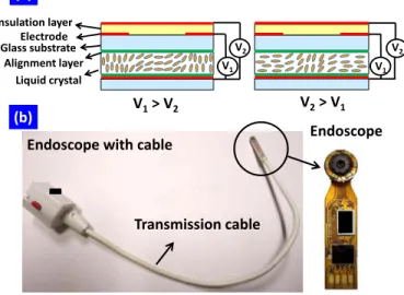
To demonstrate the electrically-tunable DOF of the endoscopic system, we adopt the LC lens with a two-mode switching operation. The two-mode switching operation means the LC lens can operate as both a positive and a negative lens by adjusting the applied voltages.[11-16] In Fig. 2(a), the LC lens operates as a positive lens when the applied voltage V1 > V2. When V1> V2, the LC directors near the rim of the aperture are reoriented more due to stronger electric fields near the rim of the aperture. As a result, for the incident polarized light the refractive index near the rim is smaller than that near the center of the LC lens. On the contrary, the LC lens operates as a negative lens when V1< V2. Since the LC directors
near the center of the aperture are reoriented more, the LC layer causes a negative lens effect. By changing the magnitude of V1 and V2, the focal length of the LC lens is electrically tunable. To further demonstrate the endoscopic system using a LC lens, we use a commercial endoscope (New Ken Technologies in Taiwan, Model: NK2458-OV7670-N/P-AWB-30-60 with 1/6” VGA CMOS Camera), as shown in Fig. 2(b).[7] The endoscope consists of arrays of LED light, an imaging lens module which has the effective lens power (i.e. Ps ) of 230 D, a white transmission cable, and a CMOS image sensor with 0.3 mega pixels. In our experiment, we remove the white cable of the endoscope in order to show the electrically-tunable DOF in endoscopic system. The endoscope was connected with a computer via an analog TV stick (Compro technology, VideoMate U2600F).
Endoscope Endoscope with cable
(a) V1 V2 Insulation layer Electrode Alignment layer Glass substrate Liquid crystal V1> V2 V2> V1 V1 V2 (b) Transmission cable
Fig. 2 (a) The structure of LC lens with a positive lens power when V1>V2 and with a negative lens power when V2>V1. (b) The
structure of the endoscope with a white transmission cable. The endoscope we adopted in our measurement is located at the head of the system.
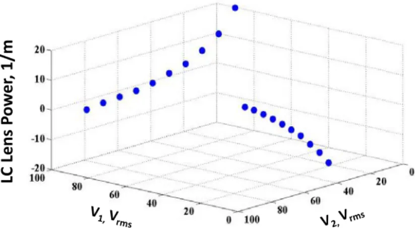
The lens power as a function of applied voltage is shown in Fig. 3. The lens power can be switched from 0 to 19.9 Diopter (D or m-1) under the operation of the positive lens as we apply a voltage of V
2 at V1=90 Vrms. As to the lens power of negative lens, the measured power can be changed from -12.5 to 0 D when we apply a voltage of V1 at V2=45Vrms. We chose the fixed V2 of 45Vrms for the negative lens and the fixed V1 of 90Vrms for the positive lens in order to achieve large tunable power while maintaining a good image quality.[11,16]
20 10 0 -10 -20 100 60 I. 20 0 100 20
LC
L
en
s P
ow
er
, 1
/m
Fig. 3 The lens power of the LC lens as functions of applied voltages V1 and V2. The LC lens is a positive lens at different V2
when V1= 90Vrms. The LC lens is a negative lens at different V1 when V2 = 45Vrms.
To measure the response times of the endoscopic system, we measured the response times of the LC lens under different operating approaches. A detector with a small pinhole (~0.2mm) was put behind the LC lens to measure the transmittance under applying voltages.[11] The experimental results are listed in Table 1. Here we classify the operating approaches into two methods: “Method 1” is the LC lens without bias voltages at initial state (V1 = V2 = 0Vrms) and “Method 2” is the LC lens with bias voltages at the initial state. According to table 1, the LC lens can be controlled from no lensing effect (initial state) to positive lens (final state) by switching the voltage pair from (V1, V2) = (0Vrms, 0Vrms) to (V1, V2) = (90Vrms, 0Vrms) and also from (V1, V2) = (90Vrms, 90Vrms) to (V1, V2) = (90Vrms, 0Vrms). The measured response times are 4.62 sec and 1.65 sec, respectively. The response times of the reverse operation from the positive lens to no lensing effect were also measured, which are 3.78 sec and 0.503 sec, respectively. In addition, the LC lens can also be controlled from no lensing effect to the negative lens by switching the voltage pair from (V1, V2) = (0Vrms, 0Vrms) to (V1, V2) = (0Vrms, 45Vrms) and also from (V1, V2) = (45Vrms, 45Vrms) to (V1, V2) = (0Vrms, 45Vrms). The measured response times are 2.67 sec and 1.395 sec, respectively. The response times of the LC lens controlling from negative lens to no lensing effect were also measured, which are 7 sec and 1.96 sec, respectively. Based on the measured response times in table 1, the operating approaches using “Method 2” with bias voltages are much faster than those in “Method 1” without bias voltages. This is because the reorientation of LC molecules with bias voltages is much faster than the LC molecules without bias voltages.[17] The response times of tunable positive LC lens power with the operating approach of “Method 2” are shown in Fig. 4. The blue lines in Fig. 4(a) and 4(b) are the peak to peak values of the applied voltages while the red lines in Fig. 4(a) and 4(b) represent the transmittances of the LC lens on the image sensor. The LC lens is focused when the transmittance is higher and defocused when the transmittance is lower. The focusing time is 1.65 sec when the voltage pair is switched from (V1, V2) = (90Vrms, 90Vrms) to (V1, V2) = (90Vrms, 0Vrms). The defocusing time is 0.503 sec when the voltage pair is switched from (V1, V2) = (90Vrms, 0Vrms) to (V1, V2) = (90Vrms, 90Vrms).
Initial state Final state Method 1 Response
time Method 2 Responsetime
No lensing effect Positive lens (0V,0V) to
(90V,0V) 4.62s (90V,90V) to (90V,0V) 1.65s
Positive lens No lensing effect (90V,0V) to
(0V,0V) 3.78s (90V,0V) to (90V,90V) 0.503s
No lensing effect Negative lens (0V,0V) to
(0V,45V) 2.67s (45V,45V) to (0V,45V) 1.395s
Negative lens No lensing effect (0V,45V) to
(0V,0V) 7s (0V,45V) to (45V,45V) 1.96s
Table 1 The measured response times of the LC lens. “Method 1” without bias voltages (V1=V2=0Vrms) is slower than
“Method 2” with bias voltages.
(a)
(b)
-0.2 0.2 0.6 1 1.4 -360 -300 -240 -180 -120-60 0 60 120 -2 -1 0 1 2 Tra nsm itta nc e, a .u. V2, V pp Time, sec -0.2 0.2 0.6 1 1.4 -120-90 -60 -300 30 60 90 120 -5 -4 -3 -2 -1 0 1 2 3 4 5 Tra nsm itta nc e, a .u. V2, V pp Time, secFig. 4 The measured response time of LC lens. (a) When the voltage pair is switched from (V1, V2) = (90Vrms, 90Vrms) to (V1, V2) =
(90Vrms, 0Vrms), (b) When the voltage pair is switched from (V1, V2) = (90Vrms, 0Vrms) to (V1, V2) = (90Vrms, 90Vrms)
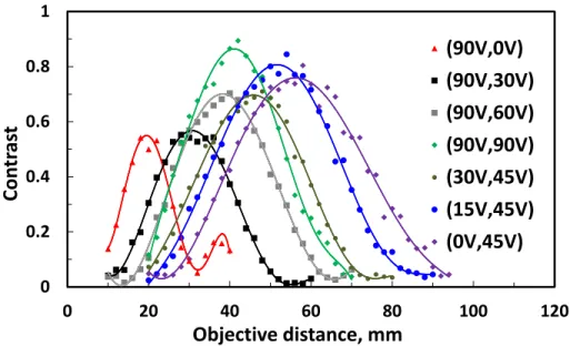
To define the DOF of the endoscopic system, a resolution chart (USAF 1951) with a spatial frequency of 2.24 lp/mm was placed in front of the endoscope. The LC lens with a polarizer was attached to the imaging lens module. The distance between the resolution chart and the LC lens is the objective distance. We recorded the images at different objective distances when the LC lens was applied with different voltages and analyzed the recorded images. The images were converted to the spatial distribution of the brightness by using software (Matlab). The contrast (C) of an image of
the resolution chart was defined as: min max min max I I I I C + −
= .[18] The Imax and Imin were the maximum and the minimum brightness of the image, respectively. We then plotted the contrast as a function of objective distance at different applied voltages of the LC lens, as shown in Fig. 5. At the voltage pair of (V1, V2) = (90Vrms, 90Vrms), the contrast increases and then decreases with the objective distance, as shown in green diamond in Fig. 5. The maximum contrast is 0.89 at (V1, V2) = (90Vrms, 90Vrms) at the objective distance of 42 mm.
0 0.2 0.4 0.6 0.8 1 0 20 40 60 80 100 120
Co
nt
ra
st
Objective distance, mm
(90V,0V)
(90V,30V)
(90V,60V)
(90V,90V)
(30V,45V)
(15V,45V)
(0V,45V)
Fig. 5 The contrast as a function of the objective distance at different voltage pairs.
The DOF in our measurement system is defined as the distance when C > 0.5 Cmax. When the voltage pair is (V1, V2) = (90Vrms, 90Vrms), the DOF of the endoscope is around 28 mm (i.e. the objective distance is from 27 mm to 55 mm as C ≧0.5Cmax.). We also measured the contrasts with different applied voltage pairs, including the red triangles with applied voltage pair (V1=90Vrms, V2=0Vrms), the black squares with voltage pair (V1=90Vrms,V2=30Vrms), the grey squares with voltage pair (V1=90Vrms,V2=60Vrms), the dark-green dots with voltage pair (V1=30Vrms,V2=45Vrms), the blue dots with voltage pair (V1=15Vrms,V2=45Vrms), the purple diamond with voltage pair (V1=0Vrms,V2=45Vrms). According to our experiments, the contrast can be controlled by adjusting the voltage pairs. The position of the maximum contrast can be controlled from 56 mm to 19.8 mm by changing the voltage pairs. This also means the objective distance of the endoscopic system is electrically tunable. Meanwhile, the DOF of the endoscopic system can also be controlled from 38.8 mm to 14.6 mm by applied voltages. Moreover, the range of the DOF can be extended originally from 27 mm ~ 55 mm to 12.4 mm ~ 76.4 mm. Therefore, the function of the LC lens in the endoscopic system is not only to shift the objective distance, but also adjust the DOF. The concept in this paper not only apply to the tunable focusing lens with few discrete lens powers but also can apply to the tunable focusing lens with a continuous lens power. In addition, other active optical lenses with discrete-focusing and fast-response properties can also be used in the endoscopic system, such as diffractive type of the LC lenses and the LC lens based on controllable polarizations.[19-23] To further enlarge the
DOF of the system, we can enlarge the LC lens power or reduce the diameter of the entrance pupil.[7]
0
20
40
60
80
-20
-10
0
10
20
30
De
pth
of
fie
ld
, m
m
LC lens power, 1/m
2.24 lp/mm 1.26 lp/mmFig. 6 Depth of field (DOF) as a function of LC lens power. The DOF for the spatial resolution of 1.26 lp/mm is depicted as the red squares and the DOF for the spatial resolution of 2.24 lp/mm is depicted as the blue hollow triangles.
In order to further investigate how the DOF changes with the LC lens power, we plotted the DOF as a function of LC lens power at two spatial frequencies: 1.26 lp/mm and 2.24 lp/mm, as shown in Fig. 6. The DOF decreases with the the LC lens power. The DOF is larger when the LC lens is operated as a negative lens and is smaller when the LC lens is operated as a positive lens. The DOF of the target with a high spatial frequency is smaller than that with a low spatial frequency. This is because the acceptable blur diameter B depends on the spatial frequency of the object. The experimental results of DOF are in good accordance with our theoretical predictions. Beside the small size of the LC lens, the power consumption of the LC lens is low ~4 µW.[24]
4. CONCLUSION
We demonstrated an endoscopic system using a liquid crystal lens (LC lens) as an active focusing element which exhibits electrically tunable depth-of-field (DOF). The optical mechanism of the endoscopic system adopting two-mode switching LC lens is introduced. Both of the objective distance and the corresponding DOF of the endoscopic system can be adjusted by the two-mode operation of LC lens: a positive lens and a negative lens. The detail derivations of the optical mechanism of the endoscopic system adopting a LC lens are investigated. We believe this study can provide a more detail understanding of an endoscopic system adopting a tunable focusing lens.
The authors are indebted to Mr. Yu-Jen Wang for technical assistance, and Mr. Paul Chen in New Ken Technologies Co. Ltd. for providing the endoscope. This research was supported mainly by Liqxtal Technology Inc. and partially by the National Science Council (NSC) in Taiwan under the contract no. NSC 101-2112-M-009 -011 -MY3.
REFERENCE
[1] M. Q. Yang, S. W. Huang, W. K. Su, H. M. Feng, Z. Y. Chen, H. M. Wu, and Y. T. Kuo, “Optimizing the depth of field for short object distance of capsule endoscope,” Proc. of SPIE 6859, 68591Q (2008).
[2] S. Kuiper, “Electrowetting-based liquid lenses for endoscopy,” Proc. of SPIE 7930, 793008 (2011).
[3] P. Rol, R. Jenny, D. Beck, F. Frankhauser, and P. F. Niederer, “Optical properties of miniatured endoscopes for ophthalmic use,” Opt. Engineering 34, 2070-2077(1995).
[4] X. Zeng, C. T. Smith, J. C. Gould, C. P. Heise, and H. Jiang, “Fiber endoscopes utilizing liquid tunable-focus microlenses actuated through infrared light,” J. of Microelectromechannical Systems 20, 583-593 (2011).
[5] S. W. Seo, S. Han, J. H. Seo, W. B. Choi, and M. Y. Sung, “Liquid lens module with wide field-of view and variable focal length,” Electronic Mater. Lett. 6, 141-144 (2010).
[6] S. W. Seo, S. Han, J. H. Seo, Y. M. Kim, M. S. Kang, N. K. Min, W. B. Choi, and M. Y. Sung, “Microelectromechanical-system-based variable-focus liquid lens for capsule endoscopes,” Jpn. J. Appl. Phys. 48, 052404 (2009).
[7] H. S. Chen, and Y. H. Lin, “An endoscopic system adopting a liquid crystal lens with an electrically tunable depth-of-field,” Opt. Express 21, 18079 (2013).
[8] Y. H. Lin, and H. S. Chen, “Electrically tunable-focusing and polarizer-free liquid crystal lenses for ophthalmic applications,” Opt. Express 21, 9428-9436 (2013).
[9] M. Katz, Introduction to Geometrical Optics (World Scientific Publishing Co. Pte. Ltd., 2002).
[10] H. Gross, H. Zugge, M. Peschka, and F. Blechinger, Handbook of Optical Systems: Aberration Theory and
Correction of Optical Systems (WILEY-VCH, 2007, Vol. 3).
[11] H. C. Lin, and Y. H. Lin, “A fast response and large electrically tunable-focusing imaging system based on switching of two modes of a liquid crystal lens,” Appl. Phys. Lett. 97, 063505 (2010).
[12] H. C. Lin and Y. H. Lin, “An electrically tunable focusing pico-projector adopting a liquid crystal lens,” Jpn. J. Appl. Phys. 49, 102502 (2010).
[13] Y. H. Lin, M. S. Chen, and C. H. Lin, “An electrically tunable optical zoom system using two composite liquid crystal lenses with a large zoom ratio,” Opt. Express 19, 4717-4721 (2011).
[14] H. C. Lin, N. Collings, M. S. Chen, and Y. H. Lin, “A holographic projection system with an electrically tuning and continuously adjustable optical zoom,” Opt. Express 20, 27222-27229 (2013).
[15] B. Wang, M. Ye, and S. Sato, “Liquid crystal lens with focal length variable from negative to positive values,” IEEE Photonics Technol. Lett. 18, 79-81 (2006).
[16] M. Ye, B. Wang, M. Uchida, S. Yanase, S. Takahashi, M. Yamaguchi, and S. Sato, “Low-voltage-driving liquid crystal lens,” Jpn. J. Appl. Phys. 49, 100204 (2010).
[17] H. Ren, and S. T. Wu, Introduction to Adaptive Lenses (John Wiley & Sons, 2012).
[18] R. El-Maksoud, L. Wang, J. M. Sasian, and V. S. Valencia, “Depth of field estimation: theory, experiment, and application,” Proc. of SPIE 7429, 74290W (2009).
[19] H. C. Lin, M. S. Chen, and Y. H. Lin, “A review of electrically tunable focusing liquid crystal lenses,” Trans. Electr. Electron Mater. 12, 234-240 (2011).
[20] Y. H. Lin, H. S. Chen, H. C. Lin, Y. S. Tsou, H. K. Hsu, and W. Y. Li, “ Polarizer-free and fast response microlens arrays using polymer-stabilized blue phase liquid crystals,” Appl. Phys. Lett. 96, 113505 (2010).
[21] P. Valley, D. L. Mathine, M. R. Dodge, J. Schwiegerling, G. Peyman, and N. Peyghambarian, “Tunable-focus flat liquid-crystal diffractive lens,” Opt. Lett. 35, 336-338 (2010).
[22] H. Ren, S. Xu, Y. Liu, and S. T. Wu, “Switchable focus using a polymeric lenticular microlens array and a polarization rotator,” Opt. Express 21, 7916-7925 (2013).
[23] H. C. Lin, and Y. H. Lin “An electrically tunable focusing liquid crystal lens with built-in planar polymeric lens,” Appl. Phys. Lett. 98, 083503 (2011).
[24] Y. S. Tsou, Y. H. Lin, and A. C. Wei, “Concentrating Photovoltaic System Using a Liquid Crystal Lens,” IEEE Photonics Technol. Lett. 24, 2239-2242 (2012).