IEEE TRANSACTIONS ON VEHICULAR TECHNOLOGY, VOL. 45, NO. 2, MAY 1996 225
Adaptive
Fuzzy Power
Control
for
CDMA Mobile Radio
Systems
Po-Rong Chang, Member,
Abstruct- This paper introduces a new application of fuzzy- logic control (FLC) theory to the power control in a direct- sequence, code-division multiple-access (DSICDMA) cellular sys- tem over the mobile fading radio channels. Power control is essential in DS/CDMA to compensate for the differing received powers due to both the slowly varying long-term and fast varying short-term fading processes and co-channel interference. The conventional feedback power control algorithms allow the base station to send a power command to either raise or lower each user transmitting signal power level by a fixed power step and then keep the received powers almost equal. The fixed-step approach is actually an integral control whose power increment is determined according to the bang-bang-like control policy. However, this control scheme suffers from poor system stability, large overshoot, and long rise time. To tackle this difficulty, a fuzzy proportional-plus-integral (PI) control, whose input vari- ables are the received power error and error change, is introduced to determine each user’s transmitting power in order to maintain simultaneously all users’ signal power received at the base station nearly equal and to achieve better system stability and control performance. The derivation of the fuzzy PI control has been carried out by analyzing both the closed-loop steady state behav- ior and transient response of the system with a priori knowledge of the dynamics of the CDMA mobile fading channels. In fuzzy control, linguistic descriptions of actions in controlling a process are represented as fuzzy rules. This fuzzy-rule base is used by an inference mechanism in conjunction with some knowledge of the states of process in order to determine control actions. These control actions would lead to the fast rise time, minimum overshoot, and small root-mean-squared (rms) tracking error. Furthermore, the additional advantages of fuzzy PI control over conventional control theories are increased robustness despite interference and the ability to handle the time-delay process without system degradation since there is usually a latency between each user and base station. Simulation results show that the fuzzy PI power control provides much smaller rms tracking error and better traffic capacity performance compared with the fixed-step control, especially in poor co-channel interference conditions.
I. INTRODUCTION
ECENTLY, the potential of greatly increasing the traffic
R
capacity of digital cellular mobile and personal radio communication systems with direct-sequence, code-division multiple-access (DS/CDMA) has been recognized [ 11, [2]. It has been shown that perfect transmitter power control can provide up to 20x
the increase in capacity, com- pared with conventional frequency-division multiple-accessManuscript received September 28, 1994; revised May 4, 1995 and August
7, 1995. This work was supported in part by the National Science Council, Taiwan, Republic of China, under contract NSC85-2221-E009-034.
The authors are with the Department of Communications Engineering, National Chiao-Tung University, Hsin-Chu, Taiwan, Republic of China.
Publisher Item Identifier S 0018-9545(96)00952-8.
IEEE, and Bor-Chin Wang
(FDMA) mobile systems [l]. A difficult problem in applying the DSKDMA to cellular mobile radio, however, is the wide variation in channel power level due to the signal fading of the mobile environment. These channels are also affected by shadowing, a slower power loss phenomenon due to physical structure blocking the transmission path between the base station and mobile units. Also, as a mobile unit moves toward or away from a base station, the received power from it increases or decreases. Hence, at a DSKDMA base station, the received power of a nearer user can be much bigger than that of a farther user, causing interference and hence degrading the communication quality for the farther user. This is known as the near-far problem. For multicell architecture,
the capacity of a DSKDMA cellular system is limited by the total interference generated by all the other users within the desired cell and from adjacent cells. Power control is thus a major design criteria in the DS/CDMA systems for two reasons: 1) to make the received power level less dependent on the fading and shadowing effects of the transmission channel and 2) to combat the near-far problem and co-channel interferences.
A number of power control methods have been proposed to minimize the effects of fading, shadowing, and near-far problems. The well-known average power control [3] that attempts to eliminate the slowly varying near-far and shad- owing effects will be affected by the fast multipath fading process, even assuming that every user moves at constant speed. To tackle this difficulty, a fixed-step power control that can accommodate the effects of rapid fading is proposed by [3]. The fixed-step power control is performed at a higher rate than the rate of multipath fading. It is suggested that the power increment command updating rate is higher than 10
x
the maximum fading rate. The power increment is determined on the basis of the deviation between the desired nominal power level and the signal level received at the base station. The user transmitting power is then created by performing the sum of the past determined power increments. From the above control actions, it is concluded that the fixed-step control is a slight modification of the integral control. Viterbi etal. [4], however, applied the same concept to their power control scheme, in which the power increment is determined according to a bang-bang-like control policy. Unfortunately, [5] showed that the integral control may make it possible to become unstable since the integrator is actually an unstable system. Moreover, the bang-bang control would yield the large overshoot, long rise time, and large steady-state error when its precalculated switching curves suffer from modeling error and
226 E E E TRANSACTIONS ON VEHICULAR TECHNOLOGY, VOL. 45, NO. 2, MAY 1996 noise [ 6 ] , [7]. Sripada et al. [7] proposed FLC to overcome the
drawbacks of both the bang-bang control and integral control. In FLC [8]-[lo], the measured variables are represented as fuzzy variables. A representation of the control signals as fuzzy variables is computed from the measurements using fuzzy logic. The essential part of FLC is a set of linguistic control rules related by the dual concept of fuzzy implication and the compositional rule of inference. In essence, FLC provides an algorithm that can convert the linguistic control strategy based on the characteristics of mobile radio channels into a power control strategy. By using the defuzzification, the fuzzy control decisions are converted to a crisp power command that is used to adjust the level of power step. To improve the controller performance further, a fuzzy proportional-plus- integral (PI) control [7], [ll], [ZO], whose input variables
are error and error change, is introduced to determine each user transmitting power in order to equalize all signal powers received at the base station. The proportional term of fuzzy PI control will effectively inciease bandwidth, improve transient response, and eliminate the system instability. Its integral term, however, forces the steady-state error to zero. The fuzzy PI control has been derived by investigating both the transient step response and steady-state behavior of the system with a priori knowledge of the dynamics of the mobile fading radio channels. The fuzzy PI control rule base can be specified through desired transient responses, linguistically expressed as fast rise time, minimum peak overshoot, and almost zero steady-state error. In Section IV, a set of lookup tables based on control rules is introduced to perform the fuzzy PI power control at a sampling rate that is higher than 10 x the fading rate. Two lookup tables will be considered in the mask ROM (read-only-memory) implementation of the fuzzy PI controller in order to achieve the high CDMA power control sampling rate. A coarse table is used to significantly reduce large power deviations. The other table carries out fine tuning when deviations are relatively small. These two decision tables are combined to shorten the settling time and to yield the minimum steady-state error. In Section V, simulation results show that the fuzzy PI power control can achieve better performance than the conventional feedback power control approach.
11. ADAPTIVE FUZZY-POWER REGULATORY
CONTROL FOR CDMA SYSTEMS
The power control for a CDMA system is used to equalize the absolute signal powers of CDMA users received at each base station. Thus, each received signal power will track a nominal step response r (t) = T d , t 2 0. If r d = 0, the problem is called a regulator problem; if T d
#
0, it is a special case of the asymptotic tracking problem [SI. For simplicity, the set point Td is usually set to be zero in decibels for the CDMA power-control problem. The conventional controllers used in the regulatory problem are the commonly used time-optimal bang-bang controller and PI controller [5], [7]. The bang-bang control policy involves switching the control input alternately from one extreme to another, at precalculated switching times. The control input is used to drive the process output to a desired set point. Viterbi et al. [4] utilized the bang-bangcontrol policy to determine the sign of each fixed transmitting- power increment. The precalculated switching times, however, are very sensitive to modeling error and noise. This would lead to large overshoot, long rise time, and large steadystate error
[6], [7]. Sripada et al. [7] propose an FLC to improve the performance of the bang-bang control policy and to adjust the switching parameters on line.
An alternative approach to regulatory control is PI control. Philips and Nagle [5] showed that the purpose of a PI controller is the same as that of a phase-lag controller, i.e., to increase stability margins and to reduce steady-state errors. In other words, it can allow for increases in steady-state accuracy without significantly increasing instability under any conditions. In general, however, phase lag (the integral part) tends to destabilize a system, since the integrator is an unstable system [SI. Observing the fixed-step power control proposed
by [3], one may find that the fixed-step control is purely an integral control with a hard-limit decision element that often makes it possible to become unstable. Thus, a proportional term should be added to the fixed-step or integral control in order to eliminate system instability, but it nevertheless has certain limitations. For example, the rise time of the system using PI control could be reduced by increasing the controller gain. This results, however, in increased overshoot. Facing this problem, a fuzzy PI control is proposed to overcome this difficulty. The conventional approach to fuzzy PI controller design is to generate a fuzzy rule base based on the system states of error and error change and the dynamics of the process, thus producing a two-input, single-output control rule base. This provides fast rise time and minimal peak overshoot, but with a possible oscillatory behavior around the set point of a magnitude comparable to the set width of the linguistic qualifier ‘‘almost zero” [7], [ll], [12]. Furthermore, [lo] has made an interesting comparison between a conventional PI controller and a fuzzy PI controller. The research showed that the fuzzy PI controller is less sensitive to large parametric changes in the process and is comparable in performance to the conventional PI controller for small parametric changes.
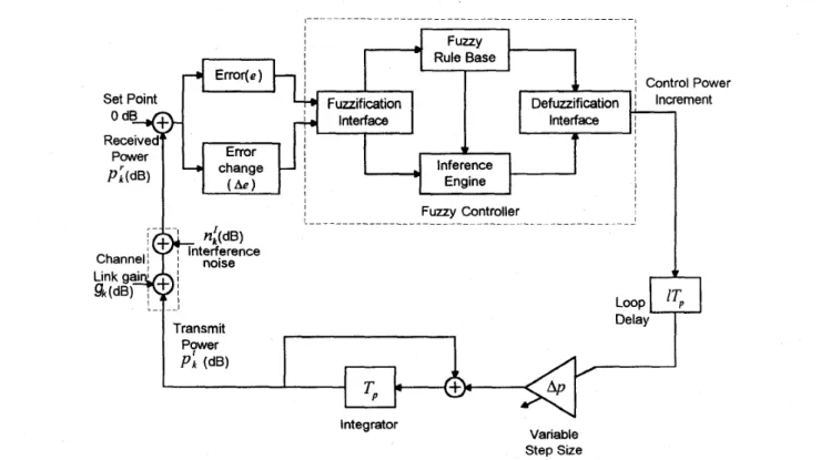
Fig. 1 illustrates the architecture of the power control system in conjunction with the fuzzy logic PI controller. Notice that all quantities are in decibels. Each user transmits a signal power
pk (dB) that is updated by a step Ap (dB) every Tp seconds
according to the fuzzy PI control rules of the form
R, : IF e is A, and Ae is B; THEN Ap is C; (1) where ( A , , B,, C,) are linguistic terms defined in the next subsection, Tp is the power control sampling period, and two
input variables e and Ae of the fuzzy PI logic controllei. specify the error and error-change signals, respectively. Error equals the set point minus the signal power level (channel output) received at the base station. Error change equals the current received power error minus the last received power error. In the mathematical sense, the user transmitting power at the kth interval is given by
P; =
+
A ~ ~ ~ ~ ( e l c - l - 1 , Aek-l-1) (2) where ApFLc(e,Ae) is the inptlt-output relationship of a fuzzy PI controller, and the extra loop delay IT, ( I : integer)CHANG AND WANG ADAPTIVE FUZZY POWER CONTROL FOR CDMA MOBILE RADIO SYSTEMS 221
Set Point
Fig. 1. Adaptive fuzzy power control system for CDMA mobile radio channels.
represents the processing time and the two-way signal prop- agation delay between mobile user and base station. During the lcth period, the signal power received at the base station is p i (=p:
+
g k+
ni)
(dB), where p ; (dB) is the received power, g k (dB) is the channel link gain due to path loss, multipath fading, and shadowing, andni
denotes the noise resulting from total interference from all the other users within and outside the desired cell. Since the interference power in decibels is not additive,ni
is then equal to {101og(PlGk+
Ik)-
1010g(PLGk)} (dB) = 1olog(l+
&) (dB) and will become&
.
A
(dB)
(Le., ln(1+
z) x z) when (W) instead of p i and Q k , and Ih represents the additive total interference power in linear units (W). This received signal power is compared with a desired set point level at the base station. For simplicity, the desired nominal level is assumed to be 0 dB. After the fuzzy PI control, the power increment command is transmitted back to the user over the return channel (forward link).>>
Ik where Pk 3 and Gk are expressed in linear unitsA. Basic Architecture of FLC Systems
The basic configuration of
FLC
comprises four principle components: a fuzzification interface, a fuzzy rule base, an inference engine, and a defuzzification interface. The fuzzi- fication interface converts the input values of both the error and error change into suitable linguistic values that may be viewed as terms of fuzzy sets. The fuzzy-rule base comprises a knowledge of the application domain and the attendant control goals. It consists of a fuzzy data base and a linguistic (fuzzy) control-rule base. The fuzzy data base is used todefine linguistic control rules and fuzzy data manipulation in FLC. The control-rule base characterizes the control goals and control policy by means of a set of linguistic control rules. The inference engine is a decision-making logic mechanism of FLC. It has the capability of simulating a mobile radio channel based on fuzzy concepts and of inferring fuzzy control actions employing fuzzy implication and the rules of inference in fuzzy logic. The defuzzification interface converts fuzzy control decisions into crisp, nonfuzzy (i.e., physical) control signals. These control signals are applied to adjust the level of power step in order to equalize the signal powers of all users received at a base station.
A fuzzy set A in a universe of discourse, U is characterized
by a membership function mA, which takes values in the interval [0,1]; that is, m~ : U -+ [ 0 , 1 ] . Thus, a fuzzy set A
in U may be represented as a set of ordered pairs. Each pair
consists of a generic element u and its grade of membership function; that is, A = { ( u , m ~ ( u ) ) I u E U } . A linguistic
variable is characterized by a quintuple (z, T ( E ) , U, G , A?) in which z is the name of the variable; T ( E ) denotes the term set of z, that is, the set of names of linguistic values of E , with each value being a fuzzy variable denoted generically by x and ranging over a universe of discourse U , which is
associated with the base variable u; G is a syntactic rule for generating the name X of values of z; and M is a
semantic rule for associating with each X its meaning, M ( X ) ,
which is a fuzzy subset of U . A particular X , that is a name
generated by G, is called a term. It should be noted that the base variable u can also be vector-valued. If E indicates the
linguistic variable for the received power error of the power control system, then its term set T ( z ) may be chosen as {large
228
/--7
@ Base station
Fig. 2. Service-area representation.
positive (LP), medium positive (MP), small positive (SP), zero (ZE), small negative (SN), medium negative (MN), or large negative (LN)}. In addition, e represents the base variable for the power error in dB with its own universe of discourse
E = {el - 18 dB
5
e5
18 dB}. Thus, M may assign a fuzzy set to the name of any term belonging to T ( x ) , for example,& f ( M P ) = { ( e , m M p ( e ) l e E E } when X is MP, where m M p ( e ) is the trapezoidal-shaped function shown in Fig. 3.
The fuzzification interface in Fig. 1 is a mapping from an input space to fuzzy sets in a certain input universe of discourse. So for a specific value u Z ( t ) at time instant t, it is mapped to the fuzzy set TJ% with degree
mi,
( u z ( t ) ) and to the fuzzy set T:% with degree m:% ( u z ( t ) ) , and so on, where Ti- isthe name of j t h term or fuzzy-set value belonging to the term set T ( x , ) . In the mobile radio power-control system, there
are two input base variables, i.e., u1 and u2, and one output base variable, u corresponding to e, Ae and A p , respectively.
Their corresponding term sets and membership functions will be determined in Section IV.
In FLC, the dynamic behavior of a fuzzy system is char- acterized by a set of linguistic description rules based on the fuzzy rule base, which contains a set of fuzzy-logic rules R.
For a multi-input/multi-output (MIMO) system
R = ( R ~ I , o , R ~ I , o , . . . l R ~ I , , } (3) where the j t h fuzzy-logic rule is
R 3 , I M o = IF(x1 is Ti: and . . . and x, is Ti?)
THEN (y1 is Tilf and . .
.
and yl is Til;) (4) where 15
j :5
p,, 15
j,”5
qt, p , and qt denote the number of fuzzy-set values of T ( x , ) and T(yt), respectively,1
5
s 5 m and 1 5 t5
1.Since the outputs of a MIMO rule are independent, the general structure of a MIMQ fuzzy system can be represented
IEEE TRANSACTIONS ON VEHICULAR TECHNOLOGY, VOL. 45, NO. 2, MAY 1996
W e ) LN MN SN
t
ZE SP MP LP -18 -12 -6 0 6 12 18 M(Aee) LN MN SNt
ZE SP MP LP M(44 LN MN SNt
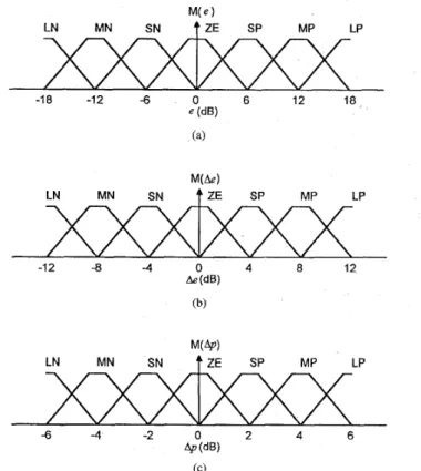
ZE SP MP LP -6 -4 -2 0 2 4 6 4J (dB) (C)Fig. 3. Membership functions for the fuzzy set values of (a) error, (b) error change, and (c) power increment.
as a collection of multi-inpudsingle-output (MISO) fuzzy systems by decomposing the above rule into
I
subrule, with Tyt as the single consequence of the ith subrule. For clarity, we shall consider a MISO system in the following analysis.The inference engine in Fig. 1 is to match the precondi- tions of rules in the fuzzy control rule base with input state linguistic terms and to perform implication. The procedure of implication is called the correlation-minimum inference or conflict-resolution process.
Note that the result of the inference process is a membership function curve. Before feeding the signal to the plant, we need a defuzzification process to get a crisp decision; the defuzzifier block in Fig. 1 serves this purpose. Among the commonly used defuzzification strategies, the center of area or fuzzy centroid-defuzzification method yields a superior result [ 131. Let c j be the j t h sample support value in the universe of discourse, Y, at which the membership function, m y ( c J ) , represents its membership value. The defuzzification output (i.e., power increment) is, therefore, calculated by
( 5 )
Notice that
c
is called a support value if m y ( ( )> 0.
111. CDMA SYSTEM MODELFig. 2 illustrates the service area that is partitioned into a number of hexagonally shaped cells. In each cell, a base sta- tion, equipped with an m-branch antenna diversity combining,
CHANG AND WANG ADAPTIVE FUZZY POWER CONTROL FOR CDMA MOBILE RADIO SYSTEMS
_____
229
is placed at the center of the cell, and the mobile unit locations are uniformly distributed over the cell area. For each base station, the CDMA system model consists of a number of K
users, each having a mobile unit, all operating simultaneously through a channel due to path loss, log-normal shadowing, and multipath fading.
A. Received Power-Signal Model
The received signal is affected by two types of fading: long- term fading due to shadowing and path loss and short-term fading due to multipath propagation. Generally, the received power, P, (W) at the base station can be expressed as
P, = G ' Pt
where Pt is the transmitted signal power and G is the link gain due to channel model defined by
(6)
G = L , S (7)
where L and S are the long-term and short-term fadings, respectively. If Pt, P,, and G can be expressed in dB units and are denoted by p t , p r , and g, respectively, then
pr = g + p t . (8)
The long-term fading L is mainly caused by the terrain configuration and the man-made environment between the base station and the mobile unit [14]. The commonly used model of
L is a product of ath power of the distance and a log-normal random variable whose standard deviation is o dB and can be expressed
L = AT-"
.
10c/lo (9) where A is a constant that depends on the parameters of transmitter and receiver, T is the distance between the base station and the mobile unit, a is called the path loss exponent, and [ is a Gaussian random variable with zero mean and standard deviation 0. In addition, the typical values of o and Q are 8 dB and 4, respectively.The long-term fading received signal is also called the local mean signal, which has a probability density function (pdf) defined by
where oLis the standard deviation (in natural log units) of L
and L is the area mean signal at a receiver located at distance T from a transmitter and equals Ar-". Since the short-term fading S arises from the multipath propagation, [15] showed that the distribution of S can be derived from the Nakagami-m
distribution of the path strength directly where the base station receiver uses m-branch antenna diversity combining. The fading on each branch is independently Rayleigh-distributed with a Doppler frequency spectrum corresponding to a uniform path arrival angle distribution. As a result, the distribution of the short-term fading for mth order diversity is given by
1 2m 2m
p ( S ) = -(-) S"-lexp(--s) (11)
r ( m ) 0 0
where l/m is the amount of fading, l / m = u u ~ - [ u ~ ] / E [ ( u ~ ) ] ~ , R = E[a2], and a is the received path strength due to the
multipath fading. Sometimes, m may be called the diversity or'der.
B. Reverse-Link Multiuser Inte$erence Model
Let P j k ( T 3 k ) denote the received power at the desired base
station due to a transmission by the kth mobile interferer (inside the j t h cell) at distance T j k from the desired base station. The total interference power, I (W) from all the interfering mobile units within and outside the desired cell is then given by
K ( 2 )
KO-1 12 1
k = l 3 = 1 k = l 3 = 1 k = l
(12) where KO is the number of active mobile units in the desired
cell, which is the center cell in Fig. 2, and
IS?)
is the number of active mobile units in cell j of tier n(n = 1 , j = 1 , 2 , . . . , 6 ; n = 2 , j = 1 , 2 , . . . , 1 2 ) ofinterferingcells surrounding the desired cell. The first term on the right-hand side of (12) represents the interference contribution from the other ( K O-
1) mobile units inside the desired cell. Without loss of generality, the index of the desired cell is set to zero and also for the simplicity of notation, P,',(,) = P l ( . ) and TO^ = T k . The second and third terms in (12) are the interference contributions from the mobile units inside the cells along the first and second tiers.C. Outage Probability Analysis
The outage probability is usually defined as the probability of failing to simultaneously achieve a signal-to-noise (thermal) ratio and a signal-to-interference (co-channel) ratio sufficient for quality communications [16], [17]. In a multicell CDMA
system where the same spectrum is reused in every cell, it is reasonable to assume that the co-channel interference is much greater than thermal noise. Under this condition, the outage probability becomes the probability failing to achieve a required SIR threshold, SIRTh, for quality communications,
and is defined by
outage probability
b
P,{SIR<
S I R T ~ } (13) where the received SIR at the base station of the desired cell is givenSIR(in linear units) = P,"/I (14) or
SIR(in decibels) = p," - i (15) where P," (W) or p," (dBW) is the signal power received at the base station due to a transmission by the desired mobile unit and 1 (W) or i (dl3W) is the total interference power received at the base station due to transmissions by all the interfering mobile units. It should be mentioned that the total interference power in decibels, i, is different from n I , defined in Section 11. Notice that the outage probability of (13) is
230 IEEE TRANSACTIONS ON VEHICULAR TECHNOLOGY, VOL 45, NO. 2, MAY 1996 computed at a given position of the desired mobile unit and
those of the interfering mobile units. However, the quality of communications in a cellular system should be characterized by a conditional outage probability (conditioned on the number of active users per cell), p,, which is obtained by many different mobile positions
p c =
J’ J’
P T { S I R<
SIRTh}f(z,Y) dxdy (16) (x,y)ERCwhere f ( z , y ) denotes the pdf for positions of the desired mobile unit as well as the interfering mobile units. (z,y) represents the rectangular coordinate of each mobile position, and R, denotes the domain containing all the cells in the
cellular system, for example, 19 cells for Fig. 2.
This conditional outage probability is usually recognized as a main criterion for the traffic capacity and communication quality of CDMA systems since the capacity is defined as the maximum number of users per cell for which the outage probability is less than a specified value [18].
I v . IMPLEMENTATION OF FUZZY PI POWER CONTROLLER Since the power-control command-updating rate must be significantly higher than 10 x the maximum fading rate, it is expected to develop a high-speed hardware to implement our fuzzy PI controller. Fortunately, there are a lot of very large scale integration (VLSI ) chips that have been designed for FLC’s [19], [20] in order to achieve the real-time execution. Jamshidi [20] uses the Togai fuzzy chip to implement the fuzzy PI controller for air conditioning systems, such that it can track the desired temperature of the chamber. An alternative approach to shorten the running time of the fuzzy PI controller is to construct a set of lookup tables based on control rules and then to program them onto mask ROM chips. The fuzzy PI control rules for CDMA systems will be derived in Section IV-
A. The procedure for constructing their associated lookup
tables is presented in Section IV-B.
A. Derivation of Fuzzy Control Rules
The selection of the fuzzy control rules has a substantial effect on the performance of FLC. There are two principal approaches to the derivation of fuzzy control rules. These two methods are not mutually exclusive, and it seems likely that a combination of them would be necessary to construct an effective method for the derivation of fuzzy control rules. Prior to the derivation of fuzzy control rules, the fuzzy- set values or terms associated with the two input linguistic variables, e and Ae, and the output control linguistic variable, Ap, should be characterized, where e, Ae, and Ap are the received power error, power-error change, and transmitted control power increment, respectively. The universes of dis- course for e, Ae, and Ap are assumed to be E={el- 18 dB
5
e
5
18 d B } , A E = {Ael - 12 dB5
Ae5
12 d B } , andA P = {ApI - 6 d B
5
Ap5
6 dB}, respectively. Theirassociated term sets, T(E), T(AE), and T(AP) are identical and given by {LP (large positive), MP (medium positive), SP (small positive), ZE (zero), SN (small negative), MN (medium
negative), and LN (large negative) ); hence, there are 7 x 7 x 7 = 343 possible combinations of the terms generating a maximum possible 343 rules of the form (1). Furthermore, the diagrammatic representation of those term sets, T(E), T(AE), and T(AP) are illustrated in Fig. 3(a)-(c), respectively. Their associated membership functions are the trapezoidal-shaped functions commonly used in real-time, fuzzy target-tracking control systems [23]. Kosko [23] showed that the lengths of the upper and lower bases in the trapezoidal membership functions will severely affect the tracking performance. A rule used to achieve the better performance is that adjacent membership functions should overlap approximately 25%. In other words, the fuzzy controller attained its best performance when the ratio between the upper and lower bases is chosen at about 50%.
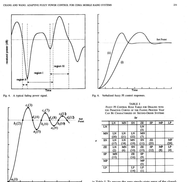
The first approach is a heuristic method in which a collection of fuzzy control rules is formed by analyzing the behavior of a controlled process. The control rules are derived in such a way that the derivation from a desired state can be corrected, and the control objective can be achieved. However, the derivation is purely heuristic in nature and relies on the qualitative knowledge of process behavior. The second approach, proposed by [9], is essentially a rule-justification method. It involves tracking a desired closed-loop second- order system trajectory in a phase plane across the domain of the FLC so that the system trajectory can terminate on a desired state. The phase plane methods have been proved very useful in analyzing the stability and system performance criterion (e.g., overshoot, rise time, and steady-state error) of linear and nonlinear second-order systems. This technique was modified by [21] by tracking the system trajectories through the linguistic phase plane instead of the real plane. It is known that the dynamic behavior of second-order systems is able to approximate a large class of practical systems [5]. Observing the typical fading process illustrated in Fig. 4, the envelope within region I can be modeled as a portion of the step response of a second-order system. In addition, the- envelope belonging to region 111 is also characterized by a portion of the step response of another second-order system with larger overshoot. In contrast to the envelope within regions I or 111, the envelope within region I1 shows the downward deep fade whose slope becomes negative infinity as it approaches the boundary between regions I and 11. Clearly, it cannot be mod- eled as any portion of the step response of simple second-order systems. From the above discussion, it is concluded that any fading process has the curves of two different primitive shapes, that is, the downward deep fades and the curves generated by second-order systems. In other words, a combination of these primitive curves can approximate the envelope of any fading process. The control actions for the fading process, therefore, are separately determined, based on the second-order systems and the behavior of downward deep fades.
Fig. 5 shows the complete step response of an open-loop second-order process to be controlled, where the input vari- ables of the fuzzy PI controller are the error ( e ) and error change (Ae). The output is the change of the process input (Ap). Typically, an expert would consider the crossover and maximudminimum points of the system step response and
CHANG AND WANG: ADAPTIVE FUZZY POWER CONTROL FOR CDMA MOBILE RADIO SYSTEMS
-
-
~ 23 1 lek I 1 I I I , I I Time Fig. 4. A typical fading power signal.c*(7)
A
c;(lD
I
Set Point Fig. 5. ~ ~ ( 5 1 , u3(9), b1(2), b2(6), b3(10), c1(3), cz(71, cs(ll), and d1(4), d z ( O d3(12) denote the crossover points and extreme points.Open-loop response of the second-order process in which ai(l),
suggest appropriate control actions at each point to generate a closed-loop response with minimum peak overshoot, fast rise time, and zero steady-state error. For example, at al(l), (e is LP and Ae is ZE) then a large positive control is required to drive the closed-loop response toward the set point generating an improvement in rise time. Notice that the rise time is the required time for the response to rise from 10 to 90% of its nominal set level [ 5 ] ; whereas, at bl(2) (e is
ZE
and Ae is LN) to prevent large peak overshoot, an LN control is recommended. Continuing with the other maximudminimum intersection points, a control rule base can be readily generatedFig. 6. Verbalized fuzzy PI control responses. TABLE I
FUZZY PI CONTROL RULE TABLE FOR DEALING WITH
THE PRIMITIVE CURVES OF THE FADING PROCESS THAT
C A N BE CHARACTERIZED BY SECOND-ORDER SYSTEMS
Ae
e
in Table I. To ensure the zero steady-state error of the closed- loop system response, consider the following rule:
Rl3 : IF e is Z E and Ae is Z E THEN Ap is Z E . (17) This rule has caused the closed-loop response to converge a stable region around the set point with the set width of linguistic qualifier ZE. The consequent defuzzified controlled response is indicated in Fig. 6 , trace (i). The response is well
damped but rather slow; this is not surprising since only 13 of the possible 343 rules have been utilized. An improved response, trace (ii), can be achieved by deriving 11 additional rules (numbers 14-24 in Table I) based on the sign changes of both e and Ae between any two consecutive regions [SI. Lee [SI shows that rule 14 has the effect of shortening the rise time and rules 15-22 are used to decrease the overshoot of system’s response.
I
232 IEEE TRANSACTIONS ON VEHICULAR TECHNOLOGY, VOL. 45, NO. 2, MAY 199612 { 8
TABLE I1
FUZZY PI CONTROL RULE TABLE FOR
DEALING WITH THE DOWNWARC DEEP FADS
~ Ae
4 4
e
It should be noted that the signs of both e and Ae are positive within region I1 since the downward deep fade de- creases below the set point level rapidly. This implies that the system error is positive and increased. The appropriate control actions for each state variable pair ( e , Ae) in region 11 should be positive in order to reduce the error. The control rules are shown in Table 11. For example, an MP control is required to drive the response toward the set point when e is SP (or MP) and Ae is any positive linguistic qualifier. In addition, it should be mentioned that the MP control is selected to raise the transmitting signal power by a medium increment level and then to avoid producing large interferences to the other users. However, it requires a large positive (LP) control to quickly drive the response to set point when e is LP and Ae is any linguistic qualifier, since the present position of the response is very far from the set point. The reverse condition of the above rule is also employed in Table I1 and given by
R : IF e is LN and Ae is any THEN A p is LN. (18) In summary, the fuzzy control actions for the two primitive curves of any fading process are not mutually exclusive, and a combination of them would provide an appropriate control action for any condition of the fading process since the fading process can be characterized by a combination of these two primitive curves.
B. Decision Table for Fuzzy-Logic Controller
A decision table relating quantized measurements to crisp control actions can be generated off line using control rules in order to shorten the running time of the FLC. In other words, the calculations of fuzzification, correlation-minimum infer- ence, and fuzzy centroid defuzzification can be performed on a computer on the basis of the control rules. After the calcula- tions, each errorlerror-change pair will have its corresponding in the form of a lookup table. Basically, the decision table is based on the discretization of both a universe of discourse and its associated membership function. Table I11 shows the quantization levels of error (e), error change (Ae), and control
~
,
I control input values. The decision table is stored in memory
~
TABLE I11
QUANTIZED ERROR, ERROR CHANGE, AND
POWER INCREMENT (COARSE CONTROL)
i
4 2
9 6 3 3
power increment ( A p ) . For example, the range of e, -18
dB
N18 dB is mapped into 13 integer quantization levels, -6 N 6.
A membership matrix table is a discretization of membership
function and can be defined by assigning grade-of-membership values to each quantization level. Table IV is an example of a membership matrix table for a membership function. It includes the error, error change, and control-power-increment variables. Each table consists of seven terms, including LP, MP, SP, ZE, SN, MN, and LN, and each set consists of 13 quantization levels, i.e., -6, -5,
. . .,
6. All error, error change, and control-power-increment variables are quantized to these 13 levels. The discrete discourse of Table 111, membership matrix table of Table IV, and control rules of Tables I and I1 are combined to form a decision table for the fuzzy controller. The decision table is shown in Table V.In the case of FLC with continuous universes, the number of quantization levels should be large enough to provide an adequate approximation and yet be small enough to save memory storage. The choice of quantization levels has an- essential influence on how fine a control can be obtained. For example, Table V may not provide optimal control when the error is approaching zero. This will lead to overshoot and hunting around the set point. To tackle this difficulty, a windowing mechanism [22] is based on a sequence or stack of nested regions in which finer levels of control and resolution are achieved every time the control rule set becomes fixed in region of the ( e , Ae) plane; for each of these regions, there is a mapping of an identical (e, Ae) grid of fuzzy qualifiers, and so on, down to the degree of resolution required. In this application, the nested region for (e, Ae) is -3 dB N 3 dB for
e and -6 dB
-
6 dB for Ae. The limit of Ap is set between-3.6 dB and 3.6 dB. Their corresponding term sets are {SP, ZE, SN} for e, {MP, SP, ZE, SN, MN} for Ae, and {MP, SP, ZE, SN, MN} for Ap. Table VI shows the quantization levels for these variables. Its associated decision table is shown in Table VII. In summary, Table V carries out coarse control when ( e , Ae) is outside the nested region. When (e, Ae) falls within the predetermined nested region, the mechanism will switch to the fine control according to Table VII. These two
CHANG AND WANG: ADAFTIVE FUZZY POWER CONTROL FOR CDMA MOBILE RADIO SYSTEMS -6 -5 -4 -3 -2 -1 0 1 2 3 4 -6 -6 -6 -6 -6 -6 -6 -6 -5 -5 -5 -6 -5 -6 -6 -6 -6 -6 -5 -5 -5 -5 -5 -6 233 5 6 -6 -6 -6 -6 TABLE IV MEMBERSHIP MATRIX TABLE
Quantized Level e Ae L\p(dB) -3.0 -6 -3.6 -2.5 -5 -3.0 -2.0 -4 -2.4 -1.5 -3 -1.8 -1.0 -2 -1.2 -0.5 -1 -0.6 0 0 0 Lmguistic Sets Quantization level -6 -5 -4 -3 -2 -1 0 TABLE V
DECISION LOOKUP TABLE FOR COARSE CONTROL de
e
2.0 2.4
2.5 3.0 5
3.0 6 3.6 6
decision tables are combined to achieve the fast response (or reduce the settling time) and minimum steady state error.
V. SIMULATION RESULTS
Numerical values of the tracking error and conditional outage probability for the fuzzy PI power control are calculated
for an example of cellular CDMA systems using Monte Carlo simulation. The following assumptions are made in the numerical computations.
The service area consists of 19 hexagonally shaped cells,
that is, the desired cell is surrounded by two tiers of interfering cells (Fig. 2).
All cells contain the same number of active mobile units, and the positions of the active mobile units within each cell are uniformly distributed with a density of K users
per base station.
Interference reduction techniques, such as cell sectoriza- tion and voice activity detection, are not considered. It is believed that the improvements from these effects can be introduced through multiplicative factors.
Each user scans signals from the closest base stations and decides to communicate with the base station that
has the largest local-mean signal power. This local-
mean signal power was determined from path loss proportional to the fourth power of the propagation distance and simulated log-normal shadow fading with standard deviation of 8 dB.
The parameters of a proposed practical CDMA system are assumed in the calculations: The spreading bandwidth is 1.25
234
e
IEEE TRANSACTIONS ON VEHICULAR TECHNOLOGY, VOL. 45, NO. 2, MAY 1996
TABLE W
DECISION LOOKUP TABLE FOR FINE CONTROL
-3000 1 I I I I I I I
o P 40 8 0 i m m i 4 0
Time( T>
Fig. 7. Comparison of the waveforms of the received signals achieved by the fuzzy PI control and 1-dB fixed-step control when I = 1, m = 2, ~ D T ~
= 0.05, and the desired mobile unit is initially placed at a position that causes a 20-dB path loss.
-
fuzzy PI, ~ fixed-step control.MHz, and the data rate is 8 kbit/s, which give a processing gain of approximately 22 dB. The required energy per bit- to-interference spectral density ratio, Eb/Io is selected as 7 dB (reverse link). Using the calculated processing gain and the selected value of required Eb/Io, the required signal-to- interference ratio threshold, S I R T ~ is found to be -15 dB (reverse link). For long-term fading, the path exponent, a is
assumed to be four, and the standard deviation for shadowing is set at 8 dB. For short-term fading, f D T p is uniformly distributed between 0.01 and 0.05, where f D denotes the Doppler rate. The diversity order, m of Nakagami distribution is assumed to be either two or four. The loop delay of the CDMA power control system is usually assumed to be unity, Le., 1 = 1 [4].
Fig. 7 illustrates the waveforms of power-controlled signals using both the fuzzy PI control and 1-dB fixed-step control
when loop delay 1 = 1, m = 2, K = 10, and the desired mobile unit is initially placed at a position that causes a 20- dB path loss, and then moves at a Doppler rate f D , where
f o T , = 0.05. A comparison of these two waveforms in Fig. 7 indicates that the fuzzy PI control can achieve much faster rise time and smaller overshoot than the fixed-step control. For fuzzy PI control, coarse decision table of Table V is applied to greatly reduce the large received power deviation at the initial time point and to quickly drive the received signal- power level toward a nominal 0 dB, since this initial power deviation results from the 20-dB path loss and total co-channel interference. Once the received power deviation becomes relatively small, Table VI1 carries out the fine tuning in order to regulate the small short-term fading and interference powers. The coarse decision table will become active again when excessively deep fades or large interference powers occur. In contrast to the above fuzzy PI control, the response of 1-dB fixed-step control is rather slow and shows substantial overshoot and oscillation. With the fuzzy controller engaged, however, the overshoot is dramatically reduced, and oscillation is effectively eliminated. Note that the rate of converge of the fuzzy PI control is nearly the same as the rate of converge of the proportional (nonfuzzy) controller. This may be due to the user-transmitting-signal power limitation. Comparing the magnitudes of those two waveforms at time instant 150 Tp,
the fuzzy PI control achieves smaller steady-state error than fixed step control. Furthermore, the performance of the power regulatory control can be characterized by the performance index called the rms tracking error. The rms tracking error is obtained by averaging the squared power error over a time window from the initial time point to 150 Tp. The fuzzy PI control results in an rms tracking error (= 3.68 dB), which is much smaller than the rms tracking error (= 6.06
dB)
of fixed- step control. The values of the rms tracking errors are listed in Table VI11 for various assumptions of foTp and the orderof diversity, m at the base-station receiver. The rms tracking errors with fuzzy PI control are always smaller than fixed- step control by a reduction ratio of about 40% (on average). For low fDT,, o;high-diversity order, both control schemes achieve the better rms tracking capability.
CHANG AND WANG ADAPTIVE FUZZY POWER CONTROL FOR CDMA MOBILE RADIO SYSTEMS m = 2 ~ 235 m = 4 TABLE VI11
COMPARISON OF RMs TRACKING ERRORS ACHIEVED BY FUZZY PI CONTROL AND
FIXED-STEP CONTROL WHEN m = 2 OR 4 AND fDTp = 0.025,0.0375, OR 0.05
fDTp =0.05 fDTF =0.025 fJ, = 0.0375 3.68 6.06 3.14 5.45 3.34 5.75 3.10 5.38 3.13 5.57 3.07 5.34
Fig. 8. Comparison of outage probabilities against the number of users per cell achieved by fuzzy PI control and 1-dE3 fixed-step control when m = 2 and S I R T h = -15 dB. -e- fixed-step control, -6- fuzzy PI.
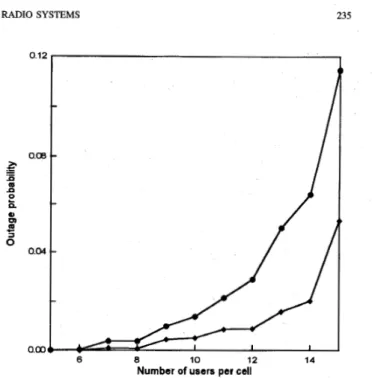
Fig. 8 shows the conditional outage probability against the
number of users per cell for fuzzy PI control and fixed-step control when the diversity order m = 2 and S I R T ~ = -15
dB.
The conditional outage probability is obtained by the empirical estimate to (16) by performing 100 runs. In addition, each outage probability involved in the calculation of the conditional outage probability can be obtained by computing the ratio between the total time the received signal whose SIR is below S I R T ~ (= -15 dB) and a time interval (= 150 Tp). Clearly, from Fig. 8 the conditional outage probabilityincreases with the active users per cell. Note that the rate of increase is more gradual, however, when fuzzy PI control is used than when fixed-step control is used. The adoption of fuzzy power control also results in a lower conditional outage probability; for example, the conditional outage probability with fixed-step control is reduced by up to 52% (on average) when the fuzzy PI control is used. For the same number of active users, the conditional outage probability is smaller for fuzzy PI control than for fixed-step control. As in Fig. 9, one may find that the conditional outage probabilities for both control schemes become smaller simultaneously when the order of diversity becomes larger, for example, m = 4. The fuzzy PI control, however, provides a much smaller outage probability than fixed-step control, by an average reduction factor of 60%. 0.12 0.08 .- E ii m
-
E n 0 0-
0.04a
Number of users per cell
Fig. 9. Comparison of outage probabilities against the number of users per cell achieved by fuzzy PI control and 1-dB fixed-step control when m = 4 and S I R T h = -15 dB. -e- fixed-step control,
-+
fuzzy PI Control.VI. CONCLUSION
This paper has introduced a feedback power control, based on fuzzy-logic theory, which is capable of maintaining for all users nearly equal signal power received at the base station over the CDMA mobile radio channels. The fuzzy PI control has been derived by analyzing both transient step response and steady-state behavior of the CDMA fading process. Forty- three fuzzy control rules based on the phase-plane method have been proposed to improve the controller performance. Two ROM-based decision tables are conducted to provide the real-time implementation for the 43-rule fuzzy controller. A coarse table is activated when the received power error at base station is relatively large. If the received power error falls within a predetermined small region, the fine control is executed by the fine-tuning decision table. For comparison of simulation results, it can be seen that the fuzzy PI control can achieve a faster rise time, small overshoot, and better rms tracking error than the fixed-step control. This better controller performance would lead to smaller outage probability and substantial capacity improvements. Simulation results show that the outage probability with fixed-step control is reduced up to 52% for m = 2 and 60% for m = 4 when the fuzzy PI control is used. Moreover, for a long time-delay CDMA fading process, the methodology proposed in our companion paper [24] is developed to modify the rule base to contain the delay information for reducing the dead-time effects of the process.
REFERENCES
[ l ] K. S. Gilhousen, I. M. Jacobs, R. Padovani, A. J. Viterbi, L. A. Weaver, and C. E. Wheatley, “On the capacity of a cellular CDMA system,”
IEEE Trans. Veh. Technol., vol. 40, pp. 303-312, May 1991. [2] F. Simpson and J. M. Holtzman, “Direct sequence CDMA power
control, interleaving, and coding,” IEEE J. Select. Areas Commun., vol. 11, no. 7, pp. 1085-1094, Sept. 1993.
IEEE TRANSACTIONS ON VEHICULAR TECHNOLOGY, VOL. 45, NO. 2, MAY 1996
S. Ariyavisitakul and L. F. Chang, “Signal and interference statistics of a CDMA system with feedback power control,” IEEE Trans. Commun., vol. 41, no. 11, Nov. 1993.
A. J. Viterbi, A. M. Viterbi, and E. Zehavi, “Performance of power controlled wideband terrestrial digital communication,” IEEE Trans.
Commun., vol. 41, pp. 559-569, 1993.
C. L. Philips and H. T. Nagle, Digital Control System Analysis and
Design.
W. L. Brogan, Modem Control Theory, 3rd ed. Englewood Cliffs,
N.J.: Prentice-Hall, 1991. Areas Commun.
N. R, Sripada, D. G. Fisher, and A. J. Moms, “AI application for process regulation and servo control setting,” IEE Proc., vol. 134, pt. D, no. 4,
DD. 251-259. 1987.
[21] M. B r a e and D. A. Rutherford, “Selection of parameters for a fuzzy logic controller,” Fuuy Sets Syst., vol. 2, no. 3, pp. 185-199, 1979. [22] W. Pedrycz, Fuzzy Control and Fuzzy Systems. New York Wiley,
1989.
[231 B. Kosko, Neural Networks and Fuuy System. Englewood, Cliffs, NJ: Prentice-Hall, 1992.
[241 p. R. Chmg and B.
c.
‘‘Adaptive fuzzy ProPo~onal-intePa1 power control for a cellular CDMA system with time delay,” accepted for publication in special issue on CDMA network 111, IEEE J. Select.Englewood Cliffs, NJ: Prentice-Hall, 1984.
I I
C. C. Lee, “Fuzzy logic in control systems: Fuzzy logic controller-Pt. I and 11,” IEEE Trans. Syst., Man, Cybern., vol. 20, no. 2, pp. 4 W 3 5 , 1990.
P. J. King and E. H. Mamdani, ‘‘De application of fuzzy control systems to industrial processes,” Automatica, vol. 13, no. 3, pp. 235-242, 1977. Y. F. Li and F. C. Lau., “Development of fuzzy algorithm for servo
systems,” IEEE Contr. Syst. Mag., vol. 9, no. 3, pp. 65-12. 1989. H. Ying, “The simplest fuzzy controllers using different inference methods are different nonlinear proportional-integral controllers with variable gain,” Automatica, vol. 29, pp. 1579-1589, 1993.
R. Katayama, Y. Kajitani, K. Kawata, and Y. Nishida, “A fast self tuning method for fuzzy controller based on adaptive learning gain algorithm,” in Proc. 7th Fuzzy Symp., 1991, pp. 21-24.
M. Braae and D. A. Rutherford, “Fuzzy relations in a control setting,”
Kybemetes, vol. 7, no. 3, pp. 185-188, 1978.
W. C. Jakes, Jr., Ed., Microwave Mobile Communications. New York Wiley, 1974.
Y.-D. Yao and A. U. H. Sheikh, “Investigations into cochannel interfer- ence in microcellular mobile radio systems,” IEEE Trans. Veh. Technol., vol. 41, no. 2, pp. 114-123, May 1992.
Y. S. Yeh and S. C. Schwartz, “Outage probability in mobile telephone due to multiple log-normal interferers,” iEEE Trans. Commun., vol. 32, pp. 380-388, Apr. 1984.
M. Zorzi and S. Pupolin, “Outage probability in multiple access packet radio networks in the presence of fading,” IEEE Trans. Veh. Technol., vol. 43, no. 3 , pp. 604-610, Aug. 1994.
R. Prasad, M. G. Jansen, and A. Kegel, “Capacity analysis of a cellular direct sequence code division multiple access system with imperfect power control,” IEICE Trans. Comm., vol. E76-B, no. 8, pp. 894-905, Aug. 1993.
M. Togai and H. Watanabe, “Expert system on chip: An engine for real-time approximation reasoning,” IEEE Expert, pp. 5 5 4 2 , Fall 1986. M. Jamshidi, “Fuzzy logic software and hardware,” in Fuzzy Logic and Control: Sojiware and Hardware Applications, M. Jamshidi et al., Eds.
Po-Rong Chang (M’87) received the B.S. degree in electrical engineering from the National Tsing- Hua University, Taiwan, Republic of China, in 1980, the M.S. degree in telecommunications engineer- ing from National Chiao-Tung University, Hsinchu, Taiwan, in 1982, and the Ph.D. degree in elec- trical engineering from Purdue University, West Lafayette, IN, in 1988.
From 1982 to 1984, he was a Lecturer in the Chi- nese Air Force Telecommunications and Electronics School. From 1984 to 1985, he was Instructor of Electrical Engineering at the National Taiwan Institute of Technology, Taipei, and from 1989 to 1990, he was Project Leader of the SPARC chip design team at ERSO, Industrial Technology and Research Institute, Chu-Tung, Taiwan. Currently, he is Associate Professor of Communications Engineering at National Chiao-Tung University. His current interests include wireless multimedia and CDMA systems, virtual reality, and fuzzy neural networks.
Englewood Cliffs, NJ: Prentice-Hall, 1993. neural networks, and PCS systems.
Bor-Chin Wang was born in Tainan, Taiwan, Re- public of China, in 1961. He received the B.S. and M.S. degrees in power mechanical engineering from the National Tsing-Hua University, Hsinchu, Taiwan, in 1983 and 1985, respectively. He is working toward the Ph.D. degree in communica- tions engineering at National Chiao-Tung Univer- sity, Hsmchu, Taiwan.
From 1985 to 1993, he was Assistant Research Engineer at the Chung-Shan Institute of Science and Technology, Ministry of National Defense, Republic of China, where he worked on servo system design. His current reiearch interests include cellular CDMA and wireless multimedia systems, fuzzy