AN APERTURE-COUPLED LINEAR
LEAKY-WAVE ANTENNA ARRAY WITH
2-D DUAL-BEAM SCANNING
CAPABILITY
Cheng-Chi Hu,1Jin-Jei Wu,2and Christina F. Jou1 1Institute of Communication Engineering
National Chiao Tung University Hsinchu, Taiwan, R.O.C.
2Department of Electrical Engineering
Kao Yuan Institute of Technology Luchu, Taiwan, R.O.C.
Recei¨ed 15 October 1999
ABSTRACT: An X-band four-element linear microstrip leaky-wa¨e
( )
antenna LWA array with a dual-beam radiation pattern and two-dimensional scanning capability is de¨eloped. The measured half-power beamwidths of the H-plane and quasi-E-plane radiation patterns are less than 30⬚. By tuning the dc bias of the¨aractor phase shifter between the antenna elements, the main beam can be scanned in the azimuth plane from y13⬚ to q13⬚ off broadside. In the ele¨ation plane, the beam-scanning angle is close to 20⬚ as the operating frequency is tuned from 11.58 to 12.5 GHz.䊚 2000 John Wiley & Sons, Inc.
Microwave Opt Technol Lett 25: 52᎐53, 2000.
Key words: leaky-wa¨e antenna; antenna beam steering; antenna array I. INTRODUCTION
A microstrip leaky-wave antenna has the characteristics of wider bandwidth, narrow beam, and frequency-scanning
capa-w x
bility 1᎐3 . Although the microstrip LWA has a narrow radiation beamwidth in the H-plane, it also produces a
typi-Ž .
cal wide patch pattern in the cross plane quasi-E-plane , given by a fixed angle to the x-axis. Related work in this area includes the development of a dual-beam four-element LWA
w x
array 4 , which was excited by a CPW feeding network, developing a narrow pencil beam. In particular, the dual-beam antenna characteristic has a great value in mobile communi-cation and automotive radar systems.
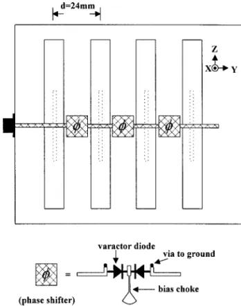
Here, we demonstrate an aperture-coupled dual-beam
se-Ž .
ries-fed array of an LWA Fig. 1 with two-dimensional scanning capability. By introducing a varactor-tuned phase shifter between the microstrip LWA elements, a constant phase progression is achieved by controlling the reverse dc bias of the varactor diodes. Therefore, the pencil beam of the microstrip LWA array can be scanned in the quasi-E-plane. The aperture coupling structure of the microstrip LWA array allows the feed network for these elements to be placed below the ground plane, avoiding interference between the feed networks and antenna radiation. This type of feeding w x has successfully been used for the excitation of an LWA 5 . Further, by feeding a microstrip leaky-wave antenna at its center, a dual-beam pattern can be obtained.
II. DESIGN AND CONSTRUCTION
Figure 1 shows the configuration of the four-element dual-beam aperture-coupled LWA. Each LWA is series-aperture-fed by a microstrip line with a characteristic impedance of 50⍀. This LWA array has a two-layer configuration, making it easy to fabricate due to its simple structure. The whole circuit is designed and fabricated on an RTrDuroid substrate with a dielectric constant s 2.2 and a thickness of 20 mils.r The aperture is placed at the center of the LWA. We utilized
Figure 1 Schematic of the aperture-coupled linear 4= 1 dual-beam 2-D scanning microstrip leaky-wave antenna array
a center-fed aperture in the ground plane, which separates the two substrates and couples the signal, thus producing a
Ž dual-beam radiation pattern. Here, a GaAs varactor M
rA-.
COM MA46410 is used as the phase-tuning element. The varactor-tuned phase shifter has a phase progressing from y50 to q50⬚ as the varactor diode bias varies from 0 to 15 V.
III. MEASUREMENT RESULTS
The measured return loss of this LWA array is shown in Figure 2, which is measured at two varactor diode bias conditions, 0 and 15 V, respectively. Good matching per-formance is obtained in the frequency region from 11.5 to 12.5 GHz without using any quarter-wave transformer. The
Ž measured VSWR in the desired frequency region 11.5᎐
.
12.5 GHz was less than 2:1 throughout the reverse varactor bias from 0 to 15 V.
The radiation pattern was measured under the far-field condition. The measured H-plane radiation patterns are shown in Figure 3 at 11.58 and 12.5 GHz. Two maxima are observed at about s "60⬚ and s "44⬚, respectively, which indicate the dual-beam and frequency-scanning charac-teristics of this LWA array.
The radiation patterns of the linear 4= 1 LWA array
Ž .
were measured on a conical surface quasi-E-plane corre-sponding to an angle of 45⬚ from the x-axis. Figure 4 shows the measured radiation patterns. The measured half-power beamwidths of the H-plane and quasi-E-plane radiation pat-terns are less than 30⬚. These measured quasi-E-plane pat-terns illustrate that the main beam can scan in azimuth from y13 to q13⬚ off broadside, corresponding to a reverse dc bias of varactor diode 0᎐15 V, respectively. The absolute gain measured from the Friss formula is about 10 dB.
MICROWAVE AND OPTICAL TECHNOLOGY LETTERS / Vol. 25, No. 1, April 5 2000
Figure 2 Return loss of the linear LWA array at two varactor diode bias conditions
Figure 3 Measured H-plane radiation patterns
IV. CONCLUSION
The work reported in this paper extends the ability of the microstrip LWA to obtain a dual-pencil-beam two-dimen-sional scanning array using a varactor-tuned phase shifter and an aperture-coupled feeding structure. A 4= 1 LWA array was demonstrated. A constant phase progression is accomplished by tuning the dc bias of the varactors, while the beam can be scanned in both azimuth and elevation in a conical scan manner. The main beam can be scanned in the azimuth plane from y13 to q13⬚ off broadside. In the elevation plane, the beam-scanning angle is close to 20⬚. The initial results shows a good potential for using this dual-beam LWA array for low-cost transmitters and collision-warning radar applications.
Figure 4 Measured quasi-E-plane radiation patterns at 12.2 GHz
REFERENCES
1. G.-J. Jou and C.-K. Tzuang, Oscillator-type active-integrated antenna: The leaky-mode approach, IEEE Trans Microwave
The-Ž .
ory Tech 44 1996 , 2265᎐2272.
2. C.-C. Hu, J.-J. Wu, and C.F. Jou, An active frequency-tuned beam scanning leaky wave antenna, Microwave Opt Technol Lett 17 Ž1998 , 43. ᎐45.
3. C.J. Wang, J.-J. Wu, and C.F. Jou, A new two-terminal feeding active leaky-wave antenna, IEEE Trans Antennas Propagat 46 Ž1998 , 1748. ᎐1749.
4. C. Luxey and J.-M. Laheurte, Dual-beam array of microstrip Ž .
leaky-wave antennas, Electron Lett 34 1998 , 1041᎐1042. 5. N.-A. Kao, C.-C. Hu, J.-J. Wu, and C.F. Jou, Active
aperture-cou-Ž .
pled leaky-wave antennas, Electron Lett 34 1998 , 2183᎐2184. 䊚 2000 John Wiley & Sons, Inc.
ON DIRECT AND INDIRECT
SCATTERING APPROACHES FOR
THE HOMOGENIZATION OF
PARTICULATE COMPOSITES
Akhlesh Lakhtakia11CATMASᎏ Computational and Theoretical Materials
Sciences Group
Department of Engineering Science and Mechanics Pennsylvania State University
University Park, Pennsylvania 16808-1401
Recei¨ed 14 October 1999
ABSTRACT: Theoretical formalisms for the homogenization of particu-late composites are identified as following either the direct scattering
( ) ( )
approach DSA or the indirect scattering approach ISA . Both ap-proaches can take inclusion size dependence and distribution statistics into account. Howe¨er, the DSA is generally limited to media with direction-independent constituti¨e properties and inclusions with simple shapes, but the ISA is not hobbled in this manner.䊚 2000 John Wiley
& Sons, Inc. Microwave Opt Technol Lett 25: 53᎐56, 2000.