An approach for seamless handoff among mobile WLAN/GPRS
integrated networks
*
Rong-Hong Jan*, Wen-Yueh Chiu
Department of Computer and Information Science, National Chiao Tung University, Hsinchu, 30050 Taiwan, ROC Received 8 October 2003; revised 4 March 2005; accepted 16 March 2005
Available online 27 April 2005
Abstract
Wireless local area networks (WLAN) and General Packet Ratio Service (GPRS) networks are two of the most widely used wireless network systems. In this paper, we propose a mobility support for mobile host roaming between WLAN and GPRS networks. In addition, a handoff decision model is presented to reduce the latency of the handoff procedure. The experimental results, including throughput, packet delay and handoff latency are given to show the performance of our approach.
q2005 Elsevier B.V. All rights reserved.
Keywords: Wireless LAN; GPRS; Seamless hand-off
1. Introduction
Over the past decade, Internet use has exploded with people gaining rich information from the World Wide Web. Meanwhile, technology has made wireless devices smaller, less expensive and more powerful. Wireless networks have become increasingly popular for accessing the Internet because they enhance mobility. People can connect to the Internet and remain on-line while roaming.
Wireless local area networks (WLAN) are the most widely-used local wireless network system in schools, offices, airports, etc. Some organizations provide free WLAN service for their members. Although the data rate for WLAN can run up to 54 Mbit/s based on the IEEE 802.11a standard, its coverage area, known as its hot spot, is too small. There is no WLAN service outside of the hot spot. Thus, users cannot leave the hot spot until all transmissions are complete. On the other hand, General Packet Ratio Service (GPRS), based on the GSM system, provides high
mobility and ‘always on’ connectivity for mobile users. However, the GPRS data rate is only up to 115 Kbit/s, and the cost of data transmission is much greater than that for WLANs. Therefore, mobile users like to have the two systems in their mobile hosts (MH). This lets people use the WLAN to access the Internet wherever it is available, yet switch to a GPRS network when they leave the hot spot.
A procedure that enables roaming between GPRS network and WLAN is known as vertical handoff. In order to achieve vertical handoff, several issues, such as handoff decision making, authentication, and mobility management, have to be addressed.
Some work on handoff decision making for
WLAN/GPRS integrated networks has been reported in the literature. In[1], the physical layer parameters, such as received signal strength and signal decay, are used as decision criteria to trigger the handoff. In[2], they present a roaming scheme based on the relative bandwidth of WLAN and GPRS. In addition to physical layer parameters and network bandwidth, the network conditions, such as user preference, packet delay and packet loss, may also be the criteria for handoff decision.
After vertical handoff decision is made, we face the authentication issue. The authentication for WLAN/GPRS integrated networks can be divided into two approaches, SIM-based and WLAN-based. In SIM-based authentication, the roaming users are authenticated and charged using GSM Subscriber Identity Module (SIM) [3]. The SIM-based www.elsevier.com/locate/comcom
0140-3664/$ - see front matter q 2005 Elsevier B.V. All rights reserved. doi:10.1016/j.comcom.2005.03.004
*
This research was supported in part by the Communications Software Technology Project of Institute for Information Industry and in part by the National Science Council, Taiwan, ROC, under grant NSC 93-2219-E-009-002 and NSC93-2752-E-009-005-PAE.
* Corresponding author. Tel.: C886 3 5731637; fax: C886 3 5721490. E-mail address: [email protected] (R.-H. Jan).
authentication works well if the WLAN system is owned by the GPRS operator. In[4], a WLAN-based authentication is proposed for the WLAN/GPRS integrated networks in which WLAN and GPRS networks can be owned by different service providers or operators. In WLAN-based authentication approach, an Authentication, Authorization, and Accounting (AAA) server, which is installed in both WLAN and GPRS networks, is required.
Next, the mobility management scheme that maintains a connection’s continuity should be considered during vertical handoff. Two major theories for mobility support have been proposed: routing-based approach and pure-end system approach.
In the routing-based approach, the home network has an agent responsible for transferring packets between the correspondent node (CN) and the MH. Mobile IP [5], a standard of mobility support for IPv4[6]that was drawn up by the Internet Engineer Task Force (IETF), is the most common solution for offering roaming in IP networks. Many studies[7–9]are based on mobile IP to support the host’s mobility. This approach does not require modifying the correspondent nodes or its applications. However, mobile IP does have some problems. First, an inefficient data flow, called a triangular routing problem, exists in this kind of approach. Second, mobile IP may not cooperate with network address translation (NAT) protocol because the IP address information was encapsulated in its registration packet. In [10], a number of network-layer (IP-layer) handoff optimization techniques, such as fast router advertisement, fast router caching, and soft handoff, that can improve handoff performance WLAN/GPRS integrated networks are proposed. In[11], a UDP tunneling method is presented to solve the NAT problem for Mobile IP.
In the pure-end system approach, the current TCP/IP structure should be modified to support host mobility. The Migrate Internet Mobility Project[12]is one of this studies proposed by the Laboratory for Computer Science at MIT. By modifying the transport layer and its applications at the end users, no agent to transfer the data is needed and better performance is achieved, compared to the routing-based approach. Clearly, the pure-end system approach is not compatible with the current network environment and is difficult to promote.
The paper applies a routing-based approach to integrate WLAN and GPRS networks to provide roaming service. The proposed method can be simply applied to the current network system without updating hardware or software. Thus, the method can be promoted easily. The architecture of our proposed system differs from the standard mobile IP. We use a virtual network interface card (virtual NIC) instead of a foreign agent. Since IP address starvation is a serious problem, NAT protocol[13]is used widely. In order to inter-operate with NAT, the UDP tunneling method is applied in this system.
A handoff decision model which is designed to reduce the packet loss rate and increasing throughput is also
proposed in this paper. By properly setting, both the threshold and hysteresis, the MH can handoff before leaving the hot spot, thus avoiding the so-called ping-pong effect. A pre-handoff mechanism is proposed to place the GPRS in a ready state before handoff occurs.
The remainder of this paper is organized as follows. In Section 2, we describe our system architecture, the message flow chart, and handoff decision model. Section 3 discusses the implementation and performance of the proposed method, and a conclusion is given in Section 4.
2. System architecture
In this section, we describe the proposed seamless service framework including system architecture, the functionality of each component, and the message sequence chart of the process.
2.1. Seamless handoff agent and proxy
Note that a host can be reached by other hosts on the Internet, depending on its IP address. If all hosts are fixed on the Internet, the packets can be routed to their destinations by examining the prefix of the destination IP address at each router. However, this mechanism limits the host’s mobility. For example, once an MH with a home IP address visits a foreign network, two problems will occur. One, there is no node in the home network to deal with packets destined to the MH. And two, no node in the home network knows where the MH is. One way to make the MH reachable is to give the MH a new IP address with the foreign network’s prefix. However, all previous connections are broken.
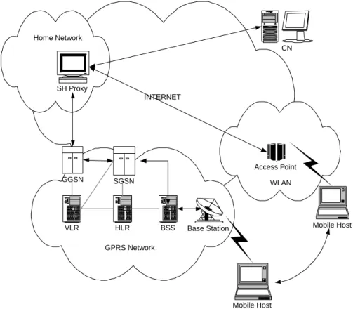
In order to provide mobility support for the MH, as shownFig. 1, a seamless handoff proxy (SH proxy) server is added to the home network for forwarding the packets destined to the MH. In addition, a software agent, called as seamless handoff agent (SH agent), is installed in the MH for tunneling mechanism and handoff management.
Now, follows a brief description of the system’s operation. As shown in Fig. 2, let H address denote the home IP address of the MH. SH agent binds H address to a virtual NIC. Note that the MH has two physical NICs, the WLAN NIC and the GPRS NIC. When MH moves to WLAN, it receives a new IP address, denoted as W address, from the foreign network. SH agent binds W address to the WLAN NIC and registers address pair (H,W) to the SH proxy. Similarly, when the mobile host moves to the GPRS network, it registers address pair (H,G) to the SH proxy where address G represents the new IP address received from GPRS.
The applications in the MH use H address as the source address to send the packet. The virtual NIC in the SH agent accepts the packet and then the SH agent tunnels the packet to the SH proxy. The SH proxy decapsulates the packet and transfers it to the CN. If CN has a packet ready to send to
MH, it uses H address as the destination address. The packet will be delivered to the home network. The SH proxy intercepts the packet destined to the H address and checks the address binding table to see if the MH is connecting to the WLAN or the GPRS. If the MH is connecting to WLAN, then the SH proxy tunnels the packet with the W address as the destination address to MH. After the MH receives the packet, the SH agent decapsulates the packet and forwards to the application via the virtual NIC.
In the following, we give a detailed description of the SH agent and SH proxy.
2.1.1. SH agent
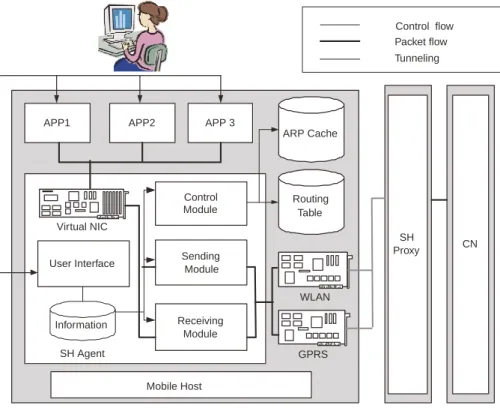
The functions of the SH agent can be divided into five modules: the virtual NIC, sending module, receiving module, control module, and user interface. Each module is a thread independently operating in the system. Fig. 3
depicts the relationships of modules in the SH agent. Descriptions of the modules are given as follows:
1. The virtual NIC is software that simulates a physical network adapter. The MH’s home IP address is bound with this virtual NIC. The connections established by applications in MH use this virtual adapter to commu-nicate with other nodes. The existing connections will not be broken while roaming because the virtual NIC would never change its IP address.
2. The sending module is responsible for transmitting packets to the SH proxy. It catches packets from the virtual NIC sent by applications, and then encapsulates the packets as payload for new UDP packets (known as UDP tunneling). Finally, it sends those tunneling packets to the SH proxy with port number 5150 via physical network adapters using existing routing rules set by the control module.
Mobile Host
Application AgentSH ProxySH CN
W
G H
Fig. 2. Brief account of the system operation. INTERNET Mobile Host SH Proxy CN GGSN SGSN BSS VLR HLR Base Station GPRS Network Home Network Mobile Host WLAN Access Point
3. The receiving module is responsible for receiving packets from the SH proxy. It receives tunneling packets with port number 5051 from the SH proxy, and then performs UDP decapsulation to get original packets. Finally, it forwards the packets to the virtual NIC; after that, the packets can be received by the corresponding application.
4. The control module is responsible to monitor all states of NICs, to select the working NIC and to execute corresponding procedures such as registration, handoff, and pre-handoff procedures. After the SH agent starts operation, the control module initializes the routing table and ARP cache. The routing table is modified according to the NICs’ priority provided by the user. The WLAN or GPRS NIC is assigned as the working NIC for the tunneling packet. The control module also keeps an eye on each NIC’s connection state until the SH agent stops the service. If the working NIC is disconnected, the control module should find another connectable NIC to communicate with the SH proxy. If a NIC with a higher priority than the current working NIC becomes con-nectable, the control module should switch to the NIC with the higher priority. The control module sends control messages using the UDP channel established by the receiving module. Thus, the SH proxy can collect both the IP address and port number from the receiving channel when the registration request or handoff request arrives. Even if the IP address or port number is changed by the NAT gateway, the SH proxy can still get a routable address to tunnel packets back to the SH agent.
5. Finally, a user interface lets the user assign some system parameters, such as the SH proxy IP address, home IP address, priority of each NIC, and so on. The user interface also shows the states of the system.
To manage all available NICs in MH, we built a table to record necessary information for each NIC. Each entry in the table includes the following fields: the NIC’s name, description, current IP address of the NIC, gateway information, connection type, priority of the NIC, current state, and its index in the operating system. Note that the connection type and priority of the NIC should be provided by the user; this helps one to adopt a proper handoff policy, and other information can be collected by the SH agent itself.
2.1.2. SH proxy
Similarly, functions of the SH proxy can be divided into four modules as given below and each module is a thread operating independently in the system (seeFig. 4). 1. The ‘FromSHAgenttoCN’ module receives tunneling
packets from the SH agent, decapsulates those packets, and sends the original packets to their target CNs. 2. The ‘FromCNtoSHAgent’ module catches packets
destined to the MH that has registered to the SH proxy, and it also encapsulates these packets and tunnels them back to the corresponding SH agent.
3. The control module deals with control messages like registration or handoff requests. It collects necessary
WLAN GPRS Virtual NIC ARP Cache Routing Table Sending Module Receiving Module Control Module User Interface
APP1 APP2 APP 3
SH Proxy CN SH Agent Information Mobile Host Control flow Packet flow Tunneling
information to update SH agent information, and sends corresponding messages back to SH agent. The SH proxy stores information for registered SH agents in a table called ‘SH agent information’. Each entry in the table contains the registered SH agent’s Home IP address, current IP address, and port number. Note that the current IP address and port number are obtained from the header of registration request or handoff request by the SH proxy itself. The packet does not carry this information in its payload.
4. The system administrator can configure the SH proxy by user interface, and it also shows internal information like the states of currently registered SH agents.
2.2. Packet structure
The packet format for the proposed method is introduced as follows. As shown in Fig. 5, four fields, the type, ID, code, and flag are defined. The type field gives the indication of packet types. The packet types and related information are summarized in Table 1. The ID field contains the SH agent’s home IP address. We use this field to identify the source node for the packet. The code field records the SH proxy’s reply. The default value is zero.
The fourth field is reserved now. Depending on different packet types, some extension is attached to the packet.
2.3. Handoff decision model
The Handoff Decision Model is designed in the control modular of the SH agent. The goal of this model is to decide when to handoff so as to improve system performance. We assume the following: One, that GPRS is always available anywhere. And two, if WLAN is available, WLAN is chosen as the access network, because it has both a higher data rate and lower cost.
The received signal strength (RSS) of WLAN varies with many factors, including landforms, obstacles, power strength of access point, etc. In general, RSS is related to the distance between the transmitter and the receiver.
Table 1 Packet types
Packet name Type Code Extension
Tunneling packet 0 0 Original packet
Registration request 1 0
Registration reply 2 1Zaccept 2Zreject MAC address of gateway Pre-handoff request 3 0 Pre-handoff reply 4 1 Handoff request 5 0 Handoff reply 6 1 SH agent deregistration 7 0 SH proxy stop 8 1 ID UDP header
IP header Type Code Flags Extension
Fig. 5. Packet fields. SH Agent CN Control flow Packet flow Tunneling FromSHAgenttoCN Module FromCNtoSHAgent Module Module Control Module User Interface Information APP SH Proxy
According to[14], the following signal propagation model may hold:
PðrÞ Z Pðr0Þ K 10a logðr=r0Þ (1)
where P(r) is signal power, in dbm, received by a given MH whose distance to the transmitter is r meters; P(r0) is the signal power at a reference point whose distance to transmitter is r0; the parameter a called the exponent value, indicates the rate of path loss.
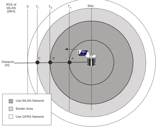
As shown inFig. 6, suppose that an MH moves out from the access point, and if the RSS is lower than threshold Tc, the MH should perform handoff from WLAN to GPRS. In a GPRS network, if MH requests to be active, then SGSN moves the MH from standby to ready state. In ready state, the MH is attached to GPRS mobility management (GMM) and thus MH can receive and send data for all relevant service types. Thus, before the RSS decreases to Tcin the WLAN, MH should send a request to GPRS for activating. Otherwise, the MH must wait until SGSN moves it from standby state to ready state. This causes both longer packet delay and packet loss.
In our decision model, prior to data transmission handoff from the WLAN to the GPRS networks, the SH agent sends a pre-handoff request to the SH proxy via the GPRS network. This causes the SGSN to move the MH from standby to ready state. We call this procedure ‘pre-handoff.’ Suppose that (1) when MH reaches point B (seeFig. 6), it sends a pre-handoff packet, and (2) when MH reaches point C, a handoff occurs (i.e. the RSS is Tc). The distance Dbc
between points B and C can by determined by: DbcZ th!vh
where vhis the moving speed of MH and this the time for performing the pre-handoff mechanism. A reference point A with distance Dato the access point is selected to measure the RSS in WLAN, say, Ta. One can then estimate the distance Dcbetween AP and the point C by applying (1) as follows.
DcZ Da10
ð1=10aÞðTaKTcÞ:
Similarly, one can apply (1) to find RSS Tbfor the point B by:
TbZ TcC10a logðDc=ðDbKDbcÞÞ
Therefore, when MH is moving and measures the RSS of AP, if the RSS decreases to Tb, the pre-handoff request should be sent periodically. This keeps GPRS NIC and the state of HM in SGSN in a ready state. When the RSS decreases to Tc, every thing is ready for handoff. This way, one can reduce both the packet delay and packet loss.
2.4. Message sequence chart
Below is an example to illustrate all of the message sequences in this current approach. As shown inFig. 7, the IP address of the home network is 140.113.167.0. The two visited networks are the WLAN network with an address of
Distance [m]
AP
Use WLAN Network Border Area Use GPRS Network RSS of WLAN [dbm] A B C Max Ta Tb Tc 0
140.113.27.0 and the GPRS network with 211.79.33.0. All IP addresses for MH are given by the dynamic host configuration protocol (DHCP) servers. Assume that MH starts from the GPRS network, moves to the WLAN network and finally returns to the GPRS network. All messages in this approach are listed below:
1. When the SH proxy starts service in the home network, it sends an ARP request to get the gateway’s MAC address. Then, two UDP channels are opened for the SH agent. Ports 5150 and 5151 are assigned to receive tunneling packets and control packets, respectively. Note that the SH proxy also uses port 5151 to send tunneling packets back to the SH agent.
2. The MH starts at the GPRS network and its SH agent sends registration request to the SH proxy. If the SH proxy accepts the request, it creates a new entry in the ‘SH agent information’ table to record related infor-mation. The SH proxy then sends proxy ARP to inform other nodes of the substitution for this MH, and sends the registration reply to the SH agent.
3. After a successful registration, the application in MH can communicate to CN. The application uses virtual NIC to send packets. Thus, the source IP address of the packets is 140.113.167.*. Next, the sending module of the SH agent encapsulates the packets into a UDP tunneling packet with a source IP address of 211.79.33.* and destination port 5150, and sends Mobile Host Registration Tunneling Pre-Handoff SH Agent off-line SH Proxy stop Application SH Agent SH Proxy CN encapsulation decapsulation encapsulation decapsulation record data send proxy ARP
start service Port 5151 Port 5151 Port 5150 Port 5151 Port 5151 Port 5151 Port 5151 Port 5151 1 2 3 4 5 6 8 10 11 registraton request registration reply tunneling packet tunneling packet pre-handoff request pre-handoff reply SP Agent stop SP Proxy stop Handoff update data Port 5151 Port 5151 9 handoff request handoff reply Handoff Port 5151 Port 5151 7 handoff request handoff reply RSS>T.p From GPRS to WLAN RSS < T.p RSS < T.h From WLAN to GPRS Start in GPRS Mobile host IP:211.79.33.* Mobile host IP:140.113.24.*
Mobile host IP:211.79.33.*
Repeat 3~6 Repeat 3~6
Stop Proxy ARP update data
the tunneling packets to SH proxy via GPRS NIC. After tunneling packets are received by the SH proxy, the ‘FromSHAgenttoCN’ module decapsulates the packets. Then, the original packets are transmitted to their destination using normal routing method.
4. CN receives the packets and transmits them back to the MH.
5. The SH proxy collects the packets that destined to the MH. By checking the IP address, the SH proxy finds the corresponding entry in the ‘SH agent information’ table and retrieves the current IP address for the MH. The ‘FromCNtoSHAgent’ module encapsulates these pack-ets with a destination IP address of 211.79.33.* and sends the tunneling packets to the SH agent via the established UDP channel.
6. When the tunneling packets arrive at the SH agent, the receiving module decapsulates these packets and then delivers them to applications via virtual NIC.
7. If the control module decides to perform a handoff from GPRS to WLAN, it changes the routing table and sends a handoff request via WLAN NIC to the SH proxy. This way, the SH proxy can update the IP address and port number. After the handoff is complete, the SH agent uses WLAN network for transmission.
8. When the RSS of WLAN is lower than Tb, the control module decides to start the pre-handoff mechanism. Thus, the SH agent sends the per-handoff message to the SH proxy via GPRS NIC to prepare handoff. The SH proxy simply returns this message to the sender. Note that the pre-handoff mechanism is done to change the MH state in the GPRS network from standby to ready. 9. The control module performs a handoff from WLAN to GPRS if RSS of WLAN is lower than Tc. After a successful handoff, the SH agent uses GPRS NIC to send packets.
10. If the SH agent decides to go off-line, it sends an ‘SH agent stop’ message to the SH proxy. Then, the SH proxy removes the entry of the SH agent from the ‘SH agent information’ table.
11. If the SH proxy wants to stop the service, it sends an ‘SH proxy stop’ message to all registered SH agents.
3. Implementation and evaluation
The following section describes the developing environ-ment, test bed and performance evaluation for the proposed system.
3.1. Developing environment
A laptop PC with two physical NICs, an Audiovox RTM 8000 GPRS card and a Lucent Orinoco volt 3.3 802.11b WLAN card, were used as the MH. An SH agent was developed in this PC. The operating system in the MH
was Microsoft windows XP professional. We used a desktop PC as the SH proxy. The operating system in the SH proxy was NT4.0. The CN was a desktop PC with some endpoint testing software.
The IP address of the home network was 140.113.167.0. The SH proxy’s IP address was 140.113.167.205 and the mobile host’s home address was 140.113.167.242. Two networks visited were the WLAN network with an address of 140.113.27.0 and the GPRS network with 211.79.33.0, respectively. The MH’s IP address in the visiting network was automatically assigned by the DHCP server. The operator of the GPRS network was Chunghwa Telecom, is the largest telecommunications company in Taiwan. Note that the ready timer of the GPRS mobility management system expired after the MH idled more than 44 s, and the transit time from standby to ready was 1–2 s. The CN was at National Central University, ChungLi City, Taiwan, with an IP address of 140.115.83.240. The distance between the MH and CN was 40 km.
3.2. Performance analysis
The following experiment shows the packet delay, the amount of packet loss caused by handoff latency, and the benefit of the handoff decision model. In addition, the compatibility of this approach with existing applications is examined.
3.2.1. Packet delay
The packet delay of this method is caused mainly by the tunneling mechanism. Since our method is based on the routing-based approach, the triangular routing problem exists. The round trip time (RTT) between the MH and CN was measured in the experiment. The RTT was composed of the packet transmitting time between the NH and SH proxy, the time of performing encapsulation/decapsulation mech-anism, and the RTT of the connection between the SH proxy and CN. Both the quality of access network and the CPU load significantly influences the RTT.
Figs. 8 and 9show the RTTs of our method from the MH to CN using the WLAN and GPRS networks, respectively. When the MH was in the WLAN, the RTT varied from 109 to 1999 ms, with an average RTT of 595 ms. (The one-way average was 297.5 ms.) When the MH was in the GPRS, the RTT varied from 992 to 11571 ms, with an average RTT of 2330.7 ms and a one-way average of 1165.4 ms. Compared to the system without mobility support, the one-way delays caused by the mobility support mechanism were 280.5 ms for WLAN and 615.44 ms for GPRS.Table 2lists the one-way packet delays for the systems with/without mobility support.
3.2.2. Handoff latency
Handoff latency is the latency caused by the handoff procedure. Comparing the handoff latencies between GPRS and WLAN, the latency for a handoff from a WLAN to
a GPRS network is longer. This is because (1) the transition time from standby to ready in GPRS should be considered; (2) the bandwidth of WLAN is much higher than that of GPRS, and (3) the handoff procedure via WLAN is faster than that of GPRS. In the experiment, the MH sent ICMP echo request messages (ping packets) to the CN every 4096 ms.
Three methods for handoffs from WLAN to GPRS network are compared below. Method 1 has a handoff procedure that does not start until the WLAN is unavailable. In Method 2, if the RSS of the WLAN is lower than a given
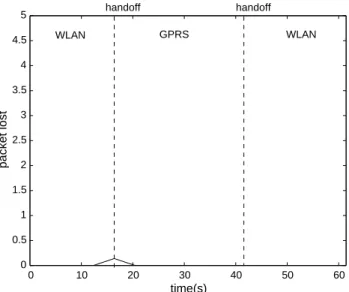
threshold, the handoff procedure starts. Method 3, our proposed method uses a handoff-decision model. Figs. 10–12 show the average numbers of packets lost for methods 1, 2 and 3, respectively, during the handoff procedures. Table 3 summarizes the average number of packets lost and handoff latencies for three methods. Packet loss is serious in Method 1 (seeFig. 10), with an average of 3.1818. In stark contrast, however, the average packet loss for Method 3 was a scant 0.1391. The average handoff delays for Methods 1–3 were 13032.9, 4542.3 and 570.1 ms, respectively. Clearly, Method 3, the proposed pre-handoff method promises far better performance.
3.2.3. Throughput evaluation
The throughput of the system is affected by the network bandwidth, the performance of the NIC and the MH CPU. We used ‘Qcheck’ software to generate UDP streams with
0 100 200 300 400 500 600 700 800 900 1000 0 2000 4000 6000 8000 10000 12000 packet sequence RTT (ms) average 2330.7 Fig. 9. RTT in GPRS. 0 10 20 30 40 50 60 0 0.5 1 1.5 2 2.5 3 3.5 4 4.5 5 time(s) packet lost handoff handoff WLAN GPRS WLAN
Fig. 11. Average packet lost with RSS decision model.
0 10 20 30 40 50 60 0 0.5 1 1.5 2 2.5 3 3.5 4 4.5 5 time(s) packet lost WLAN GPRS WLAN handoff handoff
Fig. 10. Average packet lost with no decision model.
Table 2
Packet delays for the systems with and without mobility support Type System without mobility
support
System with mobility support WLAN 10–20 ms 297.5 ms GPRS 550–600 ms 1165.4 ms 0 100 200 300 400 500 600 700 800 900 1000 0 200 400 600 800 1000 1200 1400 1600 1800 2000 packet sequence RTT(ms) average 595 Fig. 8. RTT in WLAN.
600 kbps in WLAN and 50 kbps in GPRS. The average throughput of WLAN was 481.14 kbps, and in GPRS networks, the average throughput was 16.82 kbps.
3.2.4. Compatibility test
Finally, we tested the compatibility of our system. Most of the applications worked normally in our system. Due to the high packet delays in GPRS networks, however, real-time application such as VoIP, did not work well. We hope such delays can be reduced in the future.
4. Conclusion
This paper presents a mobility support method to integrate WLAN and GPRS networks. This approach contains an SH proxy in a home network and an SH agent installed in the MH. A handoff decision model is designed to improve overall performance.
From the operator’s point of view, our approach reduces the need to modify the existing environment, and the decision model also reduces the handoff latency from the WLAN to GPRS networks. Hence, operators can simply use this approach to provide roaming services for the integrated networks. From the user’s point of view, only an SH agent is needed to install in his or her own mobile equipment, and all existing applications can still be run.
Looking ahead, developing both a security mechanism and billing system for integrated WLAN and GPRS networks might be interesting future work.
References
[1] Q. Zhang, C. Guo, Z. Guo, W. Zhu, Efficient mobility management for vertical handoff between WWAN and WLAN, IEEE Commun. Mag. 41 (2003) 102–108.
[2] K. Pahlavan, et al., Handoff in hybrid mobile data networks, IEEE Person. Commun. 7 (2000) 34–47.
[3] J. Ala-Laurila, J. Mikkonen, J. Rinnemaa, Wireless LAN access network architecture for mobile operators, IEEE Commun. Mag. 39 (2001) 82–89.
[4] M. Jiang, J. Chen, Y. Liu, WLAN-centric authentication in integrated GPRS-WLAN networks, Vehicular Technology Conference (VTC), vol. 3, 2003 pp. 2242–2246.
[5] C. Perkins, IP Mobility Support, IETF RFC 2002, 1996. [6] J. Postel, Internet Protocol, STD 5, IETF RFC 791, 1981.
[7] First Steps Towards UMTS: Mobile IP Services. A European Testbed (FIT-MIP), [online]. Avaliable: http://www.eurescom.de/wftproot/ web-deliverables/public/P1000-series/P1013/.
[8] M. Ylianttila, M. Pande, J. Makela, P. Mahonen, Optimization scheme for mobile users performing vertical handoffs between IEEE 802.11 and GPRS_EDGE networks, IEEE Global Telecommun. Confer. 6 (2001) 3439–3443.
[9] I. Wu, W. Chen, H. Liao, F. Young, A seamless handoff approach of mobile IP protocol for mobile wireless data networks, IEEE Trans. Consumer Electron. 48 (2002) 335–344.
[10] R. Chakravorty et al., Performance Issues with Vertical Handovers— Experiences from GPRS Cellular and WLAN Hot-spots Integration, Proceeding of the Second IEEE Annual Conference on Pervasive Computing and Communications, March 2004, pp. 155–164. [11] H. Levkowetz, S. Vaarala, Mobile IP NAT/NAPT Traversal using
UDP Tunneling, draft-ietf-mobileip-nat-traversal-07.txt, work in progress, IETF Internet-Draft, Nov. 2002.
[12] Migrate Internet Mobility Project [online]. Available:http://nms.lcs. mit.edu/projects/migrate/.
[13] K. Egevang, P. Francis, The IP network address translator (NAT), IETF RFC 1631, 1994.
[14] Y. Chen, H. Kobayashi, Signal strength based indoor geolocation, IEEE Int. Confer. Commun. 1 (2002) 436–439.
0 10 20 30 40 50 60 0 0.5 1 1.5 2 2.5 3 3.5 4 4.5 5 time(s) packet lost WLAN GPRS WLAN handoff handoff
Fig. 12. Average packet lost with our decision model.
Table 3
Packet loss and handoff latency for methods 1—3
Avg. number of packet loss Handoff latency
Method 1 3.1818 13032.9 ms
Method 2 1.1089 4542.3 ms