行政院國家科學委員會專題研究計畫 成果報告
利用延性破壞準則建構金屬成形摩擦模式之研究
研究成果報告(精簡版)
計 畫 類 別 : 個別型 計 畫 編 號 : NSC 96-2221-E-151-041- 執 行 期 間 : 96 年 08 月 01 日至 97 年 10 月 31 日 執 行 單 位 : 國立高雄應用科技大學模具工程系 計 畫 主 持 人 : 張朝誠 計畫參與人員: 碩士班研究生-兼任助理人員:王騰鉸 碩士班研究生-兼任助理人員:陳建宏 碩士班研究生-兼任助理人員:郭武麓 碩士班研究生-兼任助理人員:黃建國 碩士班研究生-兼任助理人員:謝典霖 處 理 方 式 : 本計畫可公開查詢中 華 民 國 98 年 01 月 30 日
行政院國家科學委員會補助專題研究計畫
■ 成 果 報 告
□期中進度報告
利用延性破壞準則建構金屬成形摩擦模式之研究
計畫類別:■個別型計畫
□ 整合型計畫
計畫編號:NSC
96-2221-E-151-041-執行期間:
96 年 08 月 01 日 至 97 年 10 月 31 日
計畫主持人:張朝誠
共同主持人:(無)
計畫參與人員:陳建宏、王騰鉸、郭武麓、黃建國、謝典霖
成果報告類型(依經費核定清單規定繳交):■精簡報告
□完整報告
本成果報告包括以下應繳交之附件:
□赴國外出差或研習心得報告一份
□赴大陸地區出差或研習心得報告一份
□出席國際學術會議心得報告及發表之論文各一份
□國際合作研究計畫國外研究報告書一份
處理方式:除產學合作研究計畫、提升產業技術及人才培育研究計畫、
列管計畫及下列情形者外,得立即公開查詢
□涉及專利或其他智慧財產權,□一年□二年後可公開查詢
執行單位:國立高雄應用科技大學 模具工程系
中
華
民
國
九十八 年
一
月 二十 日
摘要
摩擦與表面微結構破壞交互作用於工件與模具接觸之介面,是影響金屬成形製程的關 鍵效應。對於摩擦效應,一般採用固定摩擦係數之模式或磨潤模式作為模擬依據。固定摩 擦係數模式之數學形式簡單,但未考慮接觸介面之工件表面鋒隨製程變化之事實,而磨潤 膜模式雖已有考慮表面鋒變化之文獻發表,但其數學形式較複雜,仍無法廣泛應用於一般 的金屬成形模擬分析中。因此,本計畫提出一個以接觸表面之微結構破壞使表面鋒發生改 變進而影響摩擦效應之概念,以延性破壞準則為基礎推導一個工件表面破壞模式,經實驗 方式決定相關係數,用以預估表面粗糙度之變化,並將其導入修改的崔斯卡摩擦模式,作 為金屬成形工件與模具接觸介面模擬之依據,發展一個隨金屬成形製程進行而變化的摩擦 模式,並將所提出之摩擦模式植入發展中之軸對稱有限元素分析程式,配合相關實驗工作 之執行,對所提構想進行驗證。 研究重點包括:(a)推導以破壞準則為基礎之摩擦模式,並植入自行研發之有限元素分 析程式中,建構一個金屬成形模擬系統; (b)進行相關之實驗工作,以建立金屬成形模擬與摩 擦模式所需的相關係數值。工作包括利用拉伸試驗獲得應力應變曲線、設計並執行破壞應 變能與表面粗糙度關係實驗、執行雙杯反向擠出實驗以驗證所提理論。 總之,本計畫以新的方法處理金屬成形介面摩擦之問題,並以實驗驗證所提模式之可 行性,不僅可用於一般之金屬成形模擬,且因為以微結構變化為摩擦模式推導之基礎,將 有利於微尺度成形之模擬分析。經由理論與實驗之研究,對於如何處理其他工程問題中之 介面摩擦效應也有進一步的貢獻。 關鍵詞:金屬成形、摩擦、破壞準則、表面鋒 AbstractThe study proposes a new method based on the ductile fracture of workpiece surface to modify the Tresca friction model for the use in metal forming simulation. The method considers the roughness change and the incomplete filling at the contact interface due to exist of surface asperities. During metal forming process, the surface asperities are being altered and mostly flatten because of fracture and wear. The surface roughness and friction conditions are thus being changed. This change can be directly related to the fracture at the contact interface. By using the proposed ductile fracture criterion, it is possible to predict the change of the surface roughness and thus the friction conditions at the workpiece-die interface in metal forming process.
The developed friction model was implanted into an in-house simulation program for the metal forming process. The experiments were carried out to determine the mechanical properties and coefficients for the proposed friction model. The double cup extrusion tests were performed. The simulated and experimental results has been analyzed to verify the proposed friction model for metal forming simulation.
報告內容
1. Introduction
Friction at the workpiece-die interface is one of important factors in a system of metal forming. It not only increases the energy consumed in the forming process, but also causes the wear on the surface of the workpiece and die. The wear thus influences the surface quality of the product and probably results in further damages in both workpiece and die. As the size of the workpiece decreases, especially in micro metal forming processes, the size effects become significant and the ratio of the surface increases. This could enlarge the effects of friction in metal forming [1]. Thus, to understand the friction at the workpiece-die interface and to develop a model for modelling its effects in the metal forming process are highly attracted research topics.
The friction and wear effects at the workpiece-die interface depend on many factors including the roughness, the contact pressure and the sliding speed. Due to strong interactions between the factors, a model considering friction and wear has not been developed for modelling the contact behaviour in the metal forming process. Many researchers, such as, Lee and Altan [2], Kobayashi et al. [3], Ramaekers and Kals [4], Sahi [5] and Chenot et al. [6], use the Coulomb friction model or the Tresca friction model to simulate the friction effects at the workpiece-die contact interface in the metal forming process. The factors for the two friction models can be obtained by the calibration curves form the simulated and experimental results of the ring compression tests or the double-backward extrusion tests. The form of the Coulomb friction model and the Tresca friction model are simple and thus commonly used to noodle metal forming problems. Nevertheless, the friction factors for the two model are constant values, and the changes of the roughness of the contact surface and the conditions of lubrication are not taken into account. Wilson [7] proposed a model for describing the types of lubrication by considerations of the lubricant thickness and the surface roughness at the contact interface in metal forming operations. Wilson and Sheu [8] proposed a model based on the change of the surface asperity due to the plastic deformation to predict the contact ratio in the cold rolling. The effective surface hardness was also considered in the model. Sutcliffe and Montmitonnet [9] applied the Tresca friction model and the method (Sutcliffe and Le [10]) for estimating the change of the surface asperity to
model the rolling of lubricated thin aluminium foils. Hsu and Huang [11] proposed a“realistic
friction model”based on thin-film lubrication conditions to deal with the friction problem in the
metal extrusion process. Although, the model was successfully used to simulate the some forming problems with relatively simple shapes, there are still obstacles to the processes, such as forging and backward extrusion, with transient conditions and relative complex shape of the products. Recently, Yang [12] tried to apply a thin-film lubrication model for three dimensional forming problems but more experimental verifications are needed. Lo and Tai [13] preformed some experiments for the deformation of the surface asperity and found that the elastic microwedges on the tools surface plays an important role on varying the contact ratio which influences the friction effects significantly. In addition, Stupkiew and Mroz [14] proposed an asperity flattening model based on bulk plastic straining but its relations with friction has not been established. The
literature reviews show the surface asperities of the workpiece are flattened, thus the contact ratio increases and the surface roughness decreases at the workpiece-die interface during metal forming process. The change of the asperities also affects lubrication regime.
The reviewed research works do not consider the interaction between the friction and the wear at the workpiece-die interface during the metal forming process. However, the deformation of surface asperity may cause the contact ratio increase and influence the lubrication. Moreover, the roughness and asperity vary with the plastic deformation of the workpiece. The experimental works conducted by Lee et al. [15], Kato [16] and Lovell and Deng [17] show that the friction is affected by the roughness, the sliding speed and the contact length at the contact interface. The parameters also are the main factors for inducing the wear [18].
Due to the fracture and induced wear on the workpiece surface, this study proposed a new approach based on the change in roughness on the surface to construct a friction model for the simulation of the metal forming process. The fracture of ductile metals may be predicted by a criterion based on the strain energy of plastic deformation [19-24]. For example, the
Cockcroft-Latham damage criterion considers the unit tensile strain energy C1 in terms of the
maximum principle stress m
1 0
f
m
C
d .Brozzo et al. also proposed a criterion C2 based on the hydraulic stress h to estimate the
fracture. 2 0 2 (1 ) 3 f h m C d
.For porous materials, Oyane et al. used a material constant A and the effective stress to
form a criterion C3 for fracture prediction.
3 0 (1 )
f m C A d
.Clift et al. proposed a criterion C4 of the unit strain energy calculated by the effective stress and
its formula is expressed as
4 0
f C
d .Rice and Tracey considered the void growth during the plastic deformation and proposed a
damage criterion as C5 5 0 exp( ) f h C B d
.In the above equations, andfare the effective strain and the effective at fracture, respectively.
The criteria, C1~C5, can be estimated from metal forming experiments, such as tensile tests or
simple upsetting tests. Gouveia et al. [19] found that two criteria proposed by both Cockroft and Oyane respectively can be sued to accurately predict the fracture in simple upsetting tests. Goijaerts et al. [22] applied different fracture criteria in the stamping processes of metal sheets. The results showed that the criteria proposed both Oyane and Rice provide good correlations with
the experimental data. Komori [23] used the criterion proposed by Oyane to predict the chevron crack in the drawn wire and obtain a good agreement with experiments. Takuda et al. [20] found that the criteria proposed by Cockcoft and Lathamn、Brozzo and Oyane are suitable for the use in the predicting the forming limit of sheets but the criterion proposed by Clift is not suitable. The above literature reviews show that the use of the fracture criteria needs the consideration of forming conditions.
The study proposes a new method based on the ductile fracture of workpiece surface to modify the Tresca friction model for the use in metal forming simulation. The method considers the roughness change and the incomplete filling at the contact interface due to exist of surface asperities. During metal forming process, the surface asperities are being altered and mostly flatten because of fracture and wear. The surface roughness and friction conditions are thus being changed. This change can be directly related to the fracture at the contact interface. By using the proposed ductile fracture criterion, it is possible to predict the change of the surface roughness and thus the friction conditions at the workpiece-die interface in metal forming process.
The developed friction model was implanted into an in-house simulation program for the metal forming process. The experiments were carried out to determine the mechanical properties and coefficients for the proposed friction model. The double-backward extrusion tests were performed. The simulated and experimental results has been analyzed to verify the proposed friction model for metal forming simulation.
2. Fracture and friction model
The microscale of the workpiece-die contact interface is shown in Figure 1. The die and the workpiece are considered as rigid and deformable bodies, respectively. During the deformation, the surface asperities of the workpiece are compressed by the dies. Fracture could also exist at the contact interface and induce wear. These phenomena cause the change of the porosity and thus the contact and friction conditions which affect metal forming processes significantly.
Figure 1. Change in surface asperity and porosity due to pressure and fracture in metal forming process
(a) Before deformation (b) Fracture and deformed Die surface Workpiece surface Force, P Fracture debits Sliding direction Local plastic deformation
The pressure and sliding effects cause the strain energy change and thus induce the fracture in the surface asperities. The surface change is shown in Figure 1. The rough surface of the workpiece in contact with the die can be treated as a porous layer. The thickness of the layer is
related to the average roughness of the surface Ra. By considering the roughness of the
workpiece surface Rw and the roughness of the die surface Rt, the effective surface roughness
e
R may be expressed as
2 2
e w t
R R R .
Due to the normal pressure n, the surface roughness will be change. The effective strain of the
porous layer e can be expressed by
f i e e e i e R R R , where i e R and f e
R are the effective roughness at initial surface and the deformed surface,
respectively. By increasing normal pressure n, the effective stress effective strain curves can be
established. The strain energy per unit volume C is expressed as
0
f C
d ,where stress may be constructed in different forms. For example, it can be formulated in
terms of the fracture criterion proposed by Crockroft and Latham in which is the maximum
principal stress. The total strain energy of the surface asperity Ct is summation of the strain
energy from the normal pressure Cn and the strain energy from sliding fracture Cs.
t s n C C C . 0 n n n C
d and t n s C d
,where the effective strain of normal pressure n is measured from simple upsetting tests without
sliding and the effective strain of sliding t is obtained from the deformed surfaces. Moreover,
n
can be controlled and can be measured in the experiments. Therefore, it is possible to
obtain the relationships between Ct and e, and the change in the surface roughness can be
estimated.
After the roughness of the workpiece surface has been estimated, it is possible to use the Wilson’smodel[7]to describethetribologicaleffects.In thisstudy,theTrescafriction model, which is common used in the metal forming process, is studied for the dray condition. The model is expressed as
k
,
where is estimated shear stress, k is the shear strength andis the friction factor. By
considering the effective roughness of the workpiece surfaceRe, the Tresca model can be written
as ( , ) s e k s v R v ,
where vs is the sliding speed at the contact interface, and is a function of Re can be
speed at the contact interface into account, but also considers the effects of the roughness on the friction in the metal forming process.
3. Modeling of metal forming
The material flow of the workpiece is described by a purely viscoplastic behaviour with the neglect of the elastic effects, i.e. the workpiece is a rigid-viscoplastic material. The flow
behaviour can be expressed by the Norton-Hoff viscoplastic potential law,( ),
1 ( ) ( 3 ) 1 m K m
to form the following constitutive equation
1 2 ( 3 )m sK ,
where s is the deviatoric stress tensor, K is the material consistency, m is the strain rate
sensitivity index and is the effective strain rate with
1/ 2 2 2 3 ij
.The material consistency can be a function of strain hardening, e.g.
0( 0 )
n
KK ,
whereK0material constant, is the effective strain, n is strain hardening index, and 0is a
small positive constant to avoid the numerical problems.
For the special case withm0, the rigid-viscoplastic potential tends to the von Mises flow
rule 0 2 3 s
with K0 3, where 0 is the yield stress. The flow rule can be applied to cold metal
forming processes in which the strain rate sensitivity may be not sensitive. It is clear that the
deviatoric stress tensor s takes zero-over-zero indeterminate form if the effective strain rate
trends to zero. The problem is treated by introducing a small constant 0 and the deviatoric
stress tensor is expressed as
0 2 2 0 2 3 s .
The workpiece is assumed as the incompressibility during the forming process. In terms of the velocity field, the incompressibility condition can be written as
( ) 0 div v ,
where v is the velocity filed. This constraint can be achieved by the Lagrange multiplier method
At the contact interface s between the workpiece and the die, the stress and the external
traction T can be expressed as follows:
n T ,
where n is the vector of the normal direction of the contact surface. The relative velocity
s
v between the workpiece and the die is calculated by
s d
v v v ,
where vdis the velocity of the die. On the contact interface c, the material point to slide on the
die surface can be written as
0
s
v n .
This constraint is imposed by the penalty method in this study.
The proposed friction model was applied to the modeling of the large deformation of
metal forming with isothermal condition. With the penalty method for dealing with impressibility,
the energy of a metal forming system can be expressed by the following equation
2 1 ( ) ( 3 ) ( ) 1 c m s K v dV div v dV vdS T vdS m
,where V and S are the volume and the sliding contact interface, respectively. is an
assigned value for dealing with the incompressible or near incompressible material flows.
4. Finite Element Formulations
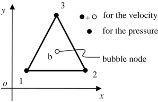
To deal with incompressible or near incompressible material flows in metal forming problems, the mini-element including a bubble node shown in Figure 3 is one of choices because of its reliability and cost effectiveness in numerical computation. The mini-element uses the conventional three-node triangle and adds an additional node at the center of the triangle to divide the triangle into three sub-triangles. The shape functions are in similar forms to those defined in the three-nodetriangle,butplusa“bubble”function 4
.
v
Ω
Figure 2. System of metal forming
Workpiece
Top die
Ωc
The bubble function 4
is a linear shape function of coordinates defined in the three sub-triangles and is equal to 1 at the center of triangle and to 0 at the edges of the triangle. Inside
an element, the velocity vi and the pressure pi in the direction of i are expressed by the
shape functions as 3 4 4 1 n b k k i i i i i k v v v V V
, and 3 1 k k i i k p P
, where n i V and n iP are the nodal velocity and pressure values in the direction of i, respectively.
The interpolation form of the global velocity in terms of the mini-element with the linear bubble function is expressed by u b v v v nu n eb eb n e V N V N
,where Nnis the shape function corresponding to the linear triangle element, and b
e
N is the
additional bubble shape function defined in the element e. The pressure field p is described by
linear three-node triangular elements as
n n n
p
P N .The strain rate ij and the term of effective strain rate are expressed as
4 4 4 3 4 4 1 1 1 1 2 2 k k k k k k k k ij i j i j i j k j i k j i j i u b v v v v v v x x x x x x
,
1 1 : 2 2 ij ij u b u b .The derivative with respect to nodal velocity component is
1 2 3 4 1 2 2 ij ij ij ij b b b b b b a a a a a a B B B B u u b u u b b b v v v v v v , wherefor the pressure
b
Figure 3. Node representation of the mini-element
x y 1 o 2 3
for the velocity
bubble node +
2 3 1 1 2 k k b k k a l b l k a l a l u u v v v x x x
, 4 4 2 4 4 1 2 b l a b l a a l l b u v v v x x x
, 4 4 2 3 1 1 2 b k k k k a l b l k a l a l u b v v v x x x
, 4 4 4 2 4 4 4 1 2 b a l b l a l a l b b v v v x x x
. The 4 b represents that only b4, i.e. bubble function, needed for the calculation.
The pressure terms p
are ( ) p ij dA d d A p iv v p
, where 3 1 l l l P N P
. 4 3 2 3 4 1 1 1 k p k l l i i l i k i i N P v v dA x x
, 4 2 3 2 4 4 1 1 1 1 1 3 p k k k k l i i e i Ae i k i k l i i i N v v dA A v P x x x
,
3 1 1 3 p b b l l e l b Ae l a a a N P dA A P v x x
,
0 p b l l d b d Ae c a c a N P dA v v v x
, 1 1 3 3 p d p b e e d b c l c l a a A A v p x p v x , 1 3 p b e b l a a A p v x . The incompressibility I terms are
2 2 1 1 2 2 I ij div v dA dA
, 4 2 3 2 4 4 1 1 1 1 k k k k ij i i i i k i i i k i v v v x x x
, 2 4 1 1 I k k e i b i k a i A v v x
, b I d b e d b a c a c a A x v v x x .By applying the finite element method and minimizing the energy with and the
Newton-Raphson method, the nodal velocity field t
V ban be solved. The newly updated nodal
t t t t
X X V t.
The strain rate tensor at the end of the increment can be calculated by
1 2 T t t t t t t t t t t v v x x ,
,
t t t t t t t t X V V .The stress tensor can be expressed by means of the strain rate tensor as tt
tt, and the
incremental displacement vector t
U
is expressed by t t
U V t
. Finally, the strain increment
can also be calculated.
5. Results and discussion
The double cup extrusion and the double groove extrusion were used for measuring friction factors from different billet surface roughness and lubrication conditions. Figure 4 shows the schematic drawing of the die set for the double cup extrusion. Copper billets with the outer diameter of 3 mm and height of 5 mm were compressed by using a screw press at a constant die
speed of 0.01 mm per second under conditions with and without lubrication of MoS2. By the
comparison with a set of calibration curves constructed by a commercial software, the friction factor of the Tresca model is in a range between 0.02 to 0.3 for different roughness of the surface (see Figure 5 and 6). In the case of surface roughness equal to Ra 1.169µm, the friction factors are about 0.05 and 0.25 for dry and lubricant conditions, respectively. As the deformation progress to the stroke of 2 mm, the factor increases to 0.3 for the dry condition. This might be that the contact ratio of billet surface to the die surface increases. However, the surface roughness was changed and close to the die surface at later stroke of 3 mm in the extrusion process. The friction factor thus decreases to about 0.2 which is closes to the value in the case with lubrication. Contrary to the dry condition, the friction factors are about 0.05 at early stage, lower at middle stage and higher at later stage. The lubrication film may become thinner and reduce the lubricant effects. Therefore, the factor increases to 0.2, close the value in dray condition. For both dry and lubricant conditions to this stage, the billet surface roughness is close to Ra 0.13µm which is the roughness of die surface. These situations also occur in the cases with the billet surface roughness of Ra 0.126µm.
Figure 7 shows the friction factors measured from the double groove extrusion and Figure 9 shows the deformed billets. The friction factor is in a range between 0.02 and 0.1 in which the billet surface roughness is about Ra 0.892µm. The factors are lower than those in the case of the double cup extrusion. One of reasons could be that the lubrication conditions are still effective because the amount of plastic deformation is less than the case of the double cup extrusion.
0 2 4 6 8 10 12 0 0.5 1 1.5 2 2.5 3 stroke(mm) H u /H l 無潤滑劑 有潤滑劑 m=0.5 m=0.4 m=0.3 m=0.2 m=0.1 m=0.02 Dry Lubricant
Figure 5. The calibration curves and measured friction factors for the billet surface roughness of Ra 1.169µm using the double cup extrusion
0 2 4 6 8 10 12 0 0.5 1 1.5 2 2.5 3 stroke(mm) H u /H l 無潤滑劑 有潤滑劑 m=0.5 m=0.4 m=0.3 m=0.2 m=0.1 m=0.02 Dry Lubricant
Figure 6. The calibration curves and measured friction factors for the billet roughness of Ra 0.126µm using the double cup extrusion
Figure 4. Schematic drawing of double cup extrusion dies
upper die
die
ejector pin. lower die punch
0 0.5 1 1.5 2 2.5 3 3.5 0 0.5 1 1.5 2 2.5 3 stroke (mm) H u /H l Dry Lubricant m=0.4 m=0.3 m=0.2 m=0.1 m=0.02
Figure 7. The calibration curves and measured friction factors for the billet surface roughness of Ra 0.829µm using the double groove extrusion
(a) Ra 1.169µm without lubricant
(c) Ra 0.126µm without lubricant (d) Ra 0.126µm with lubricant
Figure 8. Double cup extrusion (strokes:1, 2 and 3 mm)
(b) Ra 1.169µm with lubricant
Figure 9. Double groove extrusion (strokes:1, 2 and 3 mm)
6. Conclusions
The study proposes a new method based on the ductile fracture of workpiece surface to modify the Tresca friction model for the use in metal forming simulation. The method considers the roughness change and the incomplete filling at the contact interface due to exist of surface asperities. During metal forming process, the surface asperities are being altered and mostly flatten because of fracture and wear. The surface roughness and friction conditions are thus being changed. This change can be directly related to the fracture at the contact interface. By using the proposed ductile fracture criterion, it is possible to predict the change of the surface roughness and thus the friction conditions at the workpiece-die interface in metal forming process.
The experiments of the double cup extrusion and the double groove extrusion show that the billet surface roughness will close to the one of the die surface for both dry and lubricant conditions. The Tresca friction factor is close to 0.2 at later stage of extrusion.
Acknowledgement
The support from the National Science Council under grant NSC 96-2221-E-151-041 is gratefully acknowledged.
References
1. Tiesler N, Engel U, Geiger M (1999) Forming of microparts-effects of miniaturization on
friction. In: vol 2, pp. 889-894
2. Lee C, Altan T (1972) Influence of flow stress and friction upon metal flow in upset
forging of rings and cylinders. J. Eng. Ind 94:775–782
3. Kobayashi S, Oh S, Altan T (1989) Metal forming and the finite-element method. Oxford
University Press, USA,
4. Ramaekers J, Kals J (1986) Mathematical representation of friction in metal forming
analysis. Annals of CIRP 35:137-140
5. Sahi M, Rahouadj R, Herbach R, Choulier D (1996) The influence of viscoplasticity in
the interpretation of the ring test. Journal of Materials Processing Technology(Switzerland) 58:286-292
6. Chenot J, Fourment L, Mocellin K (2002) Numerical treatment of contact and friction in
fe simulation of forming processes. J Mater Process Technol 125:45-52
7. Wilson W (1979) Friction and lubrication in bulk metal-forming processes. J. Appl.
Metalwork 1:7-19
8. Wilson W, Sheu S (1988) Real area of contact and boundary friction in metal forming.
International journal of mechanical sciences 30:475-489
9. Sutcliffe M, Montmitonnet P (2001) Numerical modelling of lubricated foil rolling.
Science et Genie des Materiaux. 436-772
mixed lubrication regime. STLE Trib. Trans. 43:39-44
11. Hsu T, Huang C (2003) The friction modeling of different tribological interfaces in
extrusion process. J Mater Process Technol 140:49-53
12. Yang T (2004) The finite element tribological analysis in metal forming process. In: Ph. D.
thesis, National Yulin University of Science and Technology, Touliu, Yulin, Taiwan,
13. Lo S, Tsai S (2002) Real-time observation of the evolution of contact area under boundary
lubrication in sliding contact. ASME Journal of Tribology 124:229-238
14. Stupkiewicz S, Morz Z (2003) Phenomenological model of real contact area evolution
with account for bulk plastic deformation in metal forming. International Journal of Plasticity 19:323-344
15. Lee B, Keum Y, Wagoner R (2002) Modeling of the friction caused by lubrication and
surface roughness in sheet metal forming. J. Mater. Process. Technol. 130-131:60-63
16. Kato K (2000) Wear in relation to friction—a review. Wear 241:151-157
17. Lovell M, Deng Z (1999) Experimental investigation of sliding friction between hard and
deformable surfaces with application to manufacturing processes. Wear 236:117-127
18. Burakowski T, Wierzchon T (1999) Surface engineering of metal. In: CRC Press, New
York
19. Gouveia B, Rodrigues J, Martins P (1996) Fracture predicting in bulk metal forming.
International journal of mechanical sciences 38:361-372
20. Takuda H, Mori K, Hatt N (1999) The application of some criteria for ductile fracture to
the prediction of the forming limit of sheet metals. J. Mater. Process. Technol. 95:116-121
21. Han H, Kim K (2003) A ductile fracture criterion in sheet metal forming process. J Mater
Process Technol 142:231-238
22. Goijaerts A, Govaert L, Baaijens F (2000) Prediction of ductile fracture in metal blanking.
Transactions of the ASME 122:476-483
23. Komori K (2003) Effect of ductile fracture criteria on chevron crack formation and
evolution in drawing. International journal of mechanical sciences 45:141-160
計畫成果自評
研究內容與原計畫相符程度 研究內容與原計畫所提大致相符,唯需要更多時間建構軸對稱問題之有限元素分析程 式,因此由原訂針對軸對稱問題更改為平面應變問題之電腦程式寫作。 達成預期目標情況 本計畫完成之工作項目為下列四項: 1. 推導計畫主持人所提出的以延性破壞準則為基礎,考慮表面鋒變化的摩擦模式。 2. 建立金屬成形平面應變問題之有限元素分析電腦程式。 3. 執行實驗驗證工作:(1)材料壓縮試驗量測應力應變曲線; (2) 雙杯逆向擠製實驗量測摩擦 係數; (3) 雙溝逆向擠出試驗檢測提出之摩擦模式。 4. 比較與分析所提摩擦模式與其他模式及實驗數據之差異。 其中第 1、3 與 4 項均達成預期目標。唯需要更多時間處理軸對稱問題之有限元素分 析程式寫作,因此第 2 項由原訂針對軸對稱問題更改為平面應變問題之電腦程式建構。 研究成果之學術或應用價值 本計畫所提之摩擦模式以反應接觸之微結構變化為出發點,考慮金屬成形過程工件表 面鋒應變能到達臨界值而破壞,使得接觸表面粗糙度發生變化。利用延性破壞觀點所建立 之摩擦模式,將可以改善傳統模擬方法以固定摩擦係數值無法反應接觸狀態改變之問題, 亦可以解決磨潤模式不易處理動態問題之缺點。此外,基於摩擦模式考量微結構之變化, 將可有效反應微金屬成形之介面摩擦問題,並可以運用於其他工程問題中,如人工關節磨 耗與刀具壽命之預測等,對摩擦與磨耗效應做更精確之模擬分析。研究成果適合在學術期 刊發表。 主要發現或其他有關價值 本研究利用表面鋒受力發生破壞現象處理摩擦模擬問題,不僅考慮變接觸介面磨耗之 事實件,並考慮工件表面鋒之微結構變化,以更直接的方式將破壞臨界值、表面鋒與粗糙 度之變化導入摩擦模式。除應用於一般金屬成形之模擬外,將提供處理微成形摩擦問題的 新研究方向。是一個處理摩擦問題之新技術,且可廣泛應用於存在摩擦效應之成形問題。可供推廣之研發成果資料表
□ 可申請專利 ■ 可技術移轉 日期:98 年 1 月 26 日國科會補助計畫
計畫名稱:利用延性破壞準則建構金屬成形摩擦模式之研究 計畫主持人:張朝誠 計畫編號:NSC 96-2221-E-151-041-學門領域:機械固力技術/創作名稱
接觸介面表面延性破壞之金屬成形摩擦模式發明人/創作人
張朝誠 本技術利用接觸表面受力造成微結構之破壞而改變摩擦效應 之概念,以破壞模式為基礎,建立一個工件表面破壞模式,經實驗 方式決定相關係數,用以預估表面粗糙度之變化,並將其導入修改 的崔斯卡摩擦模式(Tresca friction model),作為金屬成形工件與模 具接觸介面模擬之依據。提出之摩擦模式乃以工件微結構變化為考 量,計算表面粗糙度隨金屬成形製程之塑性變形而發生破壞之現 象,並將此變化摩擦模式,用於金屬成形模擬。技術說明
The study proposes a new method based on the ductile fracture of workpiece surface to modify the Tresca friction model for the use in metal forming simulation. The method considers the roughness change and the incomplete filling at the contact interface due to exist of surface asperities. During metal forming process, the surface asperities are being altered and mostly flatten because of fracture and wear. The surface roughness and friction conditions are thus being changed. This change can be directly related to the fracture at the contact interface. By using the proposed ductile fracture criterion, it is possible to predict the change of the surface roughness and thus the friction conditions at the workpiece-die interface in metal forming process.