行政院國家科學委員會專題研究計畫 成果報告
子計畫四:被動光環型網路之中央節點的設計與建構(I)
計畫類別: 整合型計畫 計畫編號: NSC93-2219-E-002-009- 執行期間: 93 年 08 月 01 日至 94 年 07 月 31 日 執行單位: 國立臺灣大學光電工程學研究所 計畫主持人: 何旻真 報告類型: 完整報告 報告附件: 出席國際會議研究心得報告及發表論文 處理方式: 本計畫可公開查詢中 華 民 國 94 年 11 月 7 日
ABSTRACTS
AND
KEYWORDS
IN
CHINESE
AND
ENGLISH
(中英文摘要
及關鍵詞)
I. 中文摘要及關鍵詞 關鍵詞:都會區域網路,被動光環,都會網路,中央節點。 本報告總結“被動光環在都會網路的應用(I)-子計畫四:被動光環型網路之中央節點的 設計與建構(I)”計畫的結果。第一年的研究成果可分為以下幾項來說明,第一、我們建構了 我們所提出的第一階段的中央節點;第二、我們著手研究使用拉曼放大器來增加光環傳輸 距離的技術;最後,我們也探討了光纖網路的其它相關技術,包括光波路由器以及利用光 纖的極化來增加傳輸容量的技術。II. ENGLISHABSTRACTANDKEYWORDS(英文摘要及關鍵詞)
Keywords:Metropolitan Area Networks, Passive Optical Ring, Metro Networks, Central Node. This report summarizes the work we have done for the project “Passive Optical Ring Networks for Metro Applications (I) – Sub-project 4: The Design and Construction of the Central Node for POR Networks (I).” The research efforts in the first year include the following parts. First, we constructed the proposed phase I central node. Second, we investigated methods to increase transmission distance of passive optical ring networks by Raman amplifiers. Last, we studied other optical network related topics, including wavelength router and capacity increase by polarization diversity technique.
TABLE
OF
CONTENTS
(目錄)
ABSTRACTS AND KEYWORDS IN CHINESE AND ENGLISH (中英文摘要及關鍵詞)...I
I. 中文摘要及關鍵詞 ...I II. ENGLISHABSTRACTANDKEYWORDS(英文摘要及關鍵詞) ...I
TABLE OF CONTENTS (目錄) ... II
CONTENTS OF THE REPORT (報告內容) ... 1
I. FOREWORD(前言) ... 1
II. RESEARCHGOALS(研究目的) ... 1
III. LITERATUREINVESTIGATION(文獻探討) ... 1
IV. RESEARCHAPPROACHES(研究方法)ANDRESULTSANDDISCUSSIONS(結果與討論) ... 1
A. Construction of Phase I Central Node ... 1
B. Raman Amplification for POR Networks ... 2
C. Other Optical Network Related Topics ... 6
V. CONCLUSIONS ... 7
REFERENCES (參考文獻) ... 7
SELF-EVALUATION (計畫成果自評)... 9
TRIP REPORT (出席國際學術會議心得報告) ... 10
I. TRIPREPORT– BY PEI-CHUN LIAO... 10
II. TRIPREPORT–BY HIS-CHENG WANG... 11
PUBLISHED PAPER (發表之論文) ... 12
I. PEI-CHUN LIAO,CLEO/PR2005 ... 12
II. HIS-CHENG WANG,OECC2005 ... 14
CONTENTS
OF
THE
REPORT
(報告內容)
I. FOREWORD(前言)
In this report, we will summarize the results of the project “Passive Optical Ring Networks for Metro Applications (I) – Sub-project 4: The Design and Construction of the Central Node for POR Networks (I).” The report is organized as follows: Section II states the research goal of this project, Section III discussed the related work in the literature, Section IV describes the approaches we have taken for this project and discusses the results, and Section V concludes the report. We will leave the discussion of the relations between the research goals and our work in a later “Self-Evaluation” section (Section 0).
II. RESEARCHGOALS(研究目的)
As stated in the proposal, the research goals of this sub-project and the integrated project are:
(i) To investigate the building blocks in the central node of a POR network.
(ii) To study methods to optimize the performance of a central node in order to support longer reach, higher capacity, and more dynamic traffic.
(iii) To demonstrate a working POR network specifically designed for densely populated cities. (iv) To study various protection schemes and the way to implement them in a POR network test-bed.
III. LITERATUREINVESTIGATION(文獻探討)
The research efforts are separated into three parts (see below). We will mention and discuss the related research work in the literature for each part in the corresponding sections.
IV. RESEARCHAPPROACHES(研究方法)ANDRESULTSANDDISCUSSIONS(結果與
討論)
In this year, we (i) constructed the proposed phase I central node, (ii) investigated methods to increase transmission distance of passive optical ring networks by Raman amplifiers, and (iii) studied other optical network related topics, including wavelength router and capacity increase by polarization diversity technique. The research approaches as well as results and discussions for each part of the research efforts will be presented in the following sub-sections.
A. Construction of Phase I Central Node
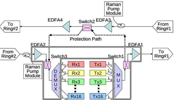
Figure 1 shows the proposed central node architecture. The area enclosed by thick gray lines is the part that we planned and did finish constructing during this year. The major components include wavelength multiplexer and demutiplexer, switches, and EDFAs. All the components were individually tested and characterized. Programs were written to control every component (if applicable) through either RS232 or National Instrument data acquisition interfaces. The control programs are written in Visual Basic 6.0 for its popularity and wide availability. Integration of the components depends strongly on the network design and is still on-going.
Tx1 Tx2 Tx3 Tx16 M U X λ1 λ2 λ3 λ16 Rx1 Rx2 Rx3 Rx16 D E M U X λ1 λ2 λ3 λ16 Protection Path EDFA1 EDFA4 EDFA2 To Ring#1 From Ring#1 To Ring#2 From Ring#2 EDFA3 Switch3 Switch1 Switch2 Raman Pump Module Raman Pump Module Tx1 Tx2 Tx3 Tx16 M U X λ1 λ2 λ3 λ16 Rx1 Rx2 Rx3 Rx16 D E M U X λ1 λ2 λ3 λ16 Protection Path EDFA1 EDFA4 EDFA2 To Ring#1 From Ring#1 To Ring#2 From Ring#2 EDFA3 Switch3 Switch1 Switch2 Raman Pump Module Raman Pump Module
Figure 1. Various models of Raman response function.
B. Raman Amplification for POR Networks
We have proposed to increase the transmission distance of POR Network to 200 km by several techniques. One of them is the use of Raman amplification. In this year, we have studied Raman amplification in order to properly design the Raman amplifier.
Raman amplification (RA) in the distributed form is a well-known technique to improve system OSNR. The OSNR improvement could potentially extend the transmission reach, increase the capacity, and/or level the channel performance across a broad signal band. In order to design the Raman amplifier properly, we have to understand both the influence of different pumping schemes and the impairments caused by RA.
Several pumping schemes for RA have been proposed and studied. They include:
(i) Counter-pumping. In this scheme, the pump and signal travel in the opposite directions. Counter-pumped Raman amplification is preferable because the relative intensity noise (RIN) transferred from pump to signal is less than that of co-pumped Raman amplification [1].
(ii) Co-pumping. In this scheme, the pump and signal travel in the same direction. Recent studies show that combining co-pumped Raman amplification with counter-pumped Raman amplification helps to increase optical signal-to-noise ratio (OSNR) [2,3].
(iii) Higher-order pumping. This scheme uses an additional wavelength to pump the “pump”. In [4], it is shown that this scheme can overcome the high loss and to improve the OSNR of 200-km fiber spans, at least twice the conventional span length in terrestrial systems. It was also shown that a high co-pumping Raman gain of 14.5 dB (limited by the available Raman pump power) provided optimum system performance to achieve 2400-km reach.
Note that there may be other variations to the above schemes and the schemes can be combined to improve the system performance.
Amplified spontaneous noise (ASE) is common to all kinds of optical amplifiers. However, RA can further impair the transmission performance because of the transient nature of the Raman effects. During the amplification process, non-ASE noise will be added to the signal in addition to the Raman gain and ASE noise. In the literature, some of the noise terms are called crosstalk or something else, but fundamentally they can be all treated as “noise” when analyzing the performance. In the following, we will use the two terms “noise” and “crosstalk” interchangeably.
The additional noise can be categorized into the following five types:
(i) Signal-to-signal crosstalk. In high-capacity broad-band systems, with WDM signal bandwidths exceeding tens of nanometers, stimulated Raman scattering between the signals causes power to be transferred from the shortest to longest wavelength channels. Therefore, all wavelengths are affected by other wavelengths, while the short wavelengths experience additional loss. Note that this type of crosstalk exists even without Raman amplification.
(ii) Pump-to-pump interaction. The same interaction as (i) could also happen between the pumps. It reduces the penetration depth for the shortest wavelength pumps, further degrading the span noise figure at short signal wavelengths. The longest wavelength pumps, on the other hand, are amplified and so penetrate deeper into the span, improving the noise figure for the longest wavelength channels.
Effects (i) and (ii) lead to an OSNR tilt across the signal band with the worst OSNR at shortest wavelengths and the best at longest. Consequently, system performance suffers because system limits are set by the worst channel.
(iii) Pump-to-signal crosstalk. The relative intensity noise (RIN) carried by the pump will be transferred to the signal through the amplification process. This is more serious for co-pumped RA than for counter-pump RA because the noise transfer is accumulated in co-pumped RA while averaged out in counter-pumped RA.
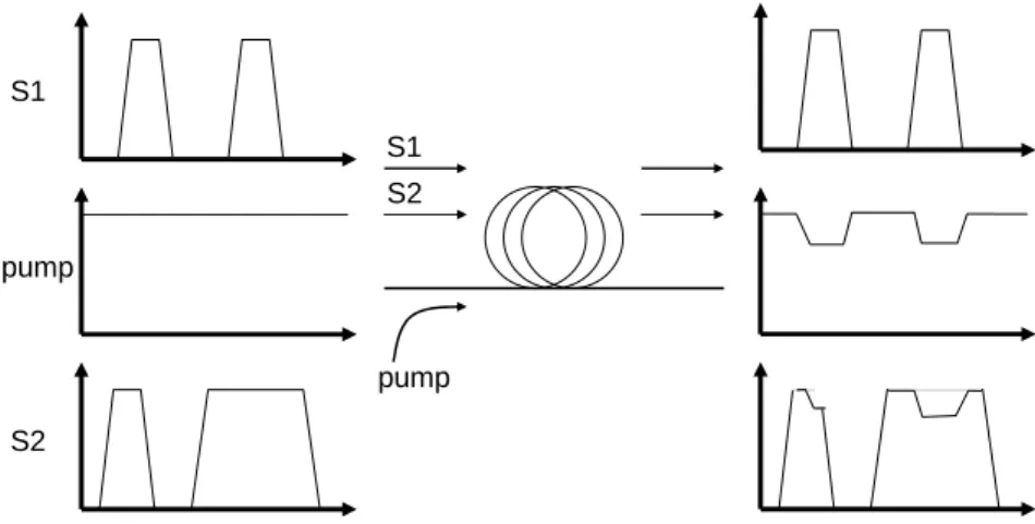
(iv) Cross gain modulation, or signal-pump-signal crosstalk. XGM originates from the modulated data signals. Refer to Figure 2, the modulation impresses noise onto the Raman pump through pump depletion. The Raman pump (even if considered a perfectly noise-less pump) becomes "noisy". The noise on the pump can be transferred to the signal through Raman gain.
Pump-signal crosstalk can be minimized by improving the pump characteristics [5]. However, cross gain modulation (XGM) is a pump-mediated crosstalk, and is therefore intrinsic to Raman amplifiers in multi-channel transmission systems.
(v) Rayleigh scattering. For long chains of distributed amplifiers, Rayleigh scattering affects the system performance in two ways: single-pass reflection of backward traveling noise into the forward direction leads to a noise figure degradation; double reflection of signal leads to crosstalk arriving at the receiver together with the signal.
Note that there are still other types of impairments other than the above four types.
S1 S2 pump pump S1 S2
Figure 2. Simplified illustration of XGM in a co-pumping Raman amplifier (Sl and S2 are signals).
From our studies, we have identified several pumping schemes worth investigating further. These schemes aim to solve one or some of the impairments outlined earlier. The schemes are listed below:
for the above-mentioned OSNR tilt, is to preferentially co-pump the shortest wavelength channels [6]. However, the price paid is the two impairments associated with co-pumping Raman amplifiers: pump-signal crosstalk and cross gain modulation.
(ii) Combined forward higher-order pumping and backward pumping. In this scheme, additional pumps are added at wavelengths one or more Stokes shifts below the conventional, first-order pumps [7]. The forward higher-order pump moves gain forward in the span and improves the span noise figure, while avoiding the direct RIN transfer from pump to signal in the case of first-order co-pumping.
(iii) Time-division multiplexed (TDM) Raman pumping. A way of overcoming pump-to-pump Raman interactions is to use pump time-division multiplexing (TDM), where different pump wavelengths are temporally separated. In pump TDM schemes, each pump wavelength is modulated out of phase with respect to the other ones in order to lower or cancel out interpump interactions [8]. However, the required higher pump power peaks potentially will cause higher amplified spontaneous emission (ASE) and Rayleigh scattered than with CW pumping [9]. (iv) Wavelength sweeping. Another possible technique to address the pump-to-pump interaction issue consists in using a tunable single-wavelength pump laser that is swept over a wavelength path [10]. The pumping scheme uses one laser (or two more-or-less identical lasers, polarization multiplexed together), with steady (dc) current drive but whose wavelength is continually and periodically scanned to produce the desired flat gain band. This has the advantages of simplicity and of resolution limited only by the bandwidth of the wavelength-scanning drive electronics
During this year, we are in the process of developing an in-house Raman design and
simulation tool that can cope with issues of various pumping schemes. The system performance
with the designed Raman amplifier is verified by commercial optical communication simulation tool OptiSystem®. In order to confirm the accuracy of this performance-verification tool, we use OptiSystem® to investigate the system impact of XGM in bi-directionally pumped, 200-km Raman amplified spans, which could be a possible scenario of our network. The results are then compared to real experimental results [11].
Refer again to Figure 2, the figure gives a qualitative description of the important parameters affecting XGM: the signal modulation characteristics, the Raman pump depletion, the Raman gain and the crosstalk bandwidth determined by fiber dispersion. For a given transmission fiber, the smaller the pump depletion and the Raman gain, the smaller the XGM is. As a result, it is preferable to use low gain in co-pumping Raman applications. For the design purpose, we are interested in not only qualitatively, but also quantitatively how much system penalty XGM causes for different co-gain levels and how much this penalty depends on different fiber characteristics. To address this issue, we built a simulation project to measure the system impact of XGM at different co-gain levels and under different fiber characteristics. The setup and results of the former issue will be presented below, while the studies of the latter issue are still on-going.
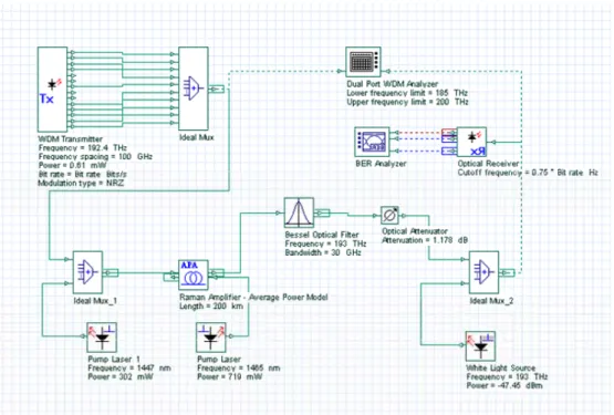
As shown in Figure 3, we simulated a C-band WDM systems. A total of 14 channels in the range of 192.4~193.7 THz (1547.72~1558.17 nm) with 100-GHz spacing were used. The bit-error-rate (BER) of the center channel at 193 THz was measured, and the two adjacent channels on each side of the center channel were turned off (see Figure 4) to minimize the effects of other types of fiber nonlinearities such as cross-phase modulation (XPM) and four-wave mixing (FWM). This left ten active channels. The signals were multiplexed and modulated with a non-return-to-zero (NRZ) pseudo-random bit sequence (PRBS) of 231-1 length at 10 Gb/s. A pump laser with center wavelength of 1447 nm was used as a co-pump. Practically, polarization-multiplexed lasers are commonly used to avoid polarization dependent gain and to provide higher pump power. In our simulation, since there was no pump laser power limitation, only one pump laser was used. The polarization dependency was left as another topic to study in the future. Another pump laser with center wavelength of 1465 nm was used to maintain 22-dB
counter-gain for all measurements. A white light laser was added before the receiver to adjust the optial signal-to-noise ratio (OSNR). The receiver’s 10-9 BER sensitivity and the corresponding OSNR after the preamplifier (hereafter called "required OSNR") were measured.
Figure 3. Simulation set-up for measuring XGM in 200-km fiber spans.
Figure 4. Signal spectrum of the transmitter.
The difficulty in determining the XGM impairment is the existence of other types of system impairments. As mentioned above, one method we adopted was to turn off adjacent channels. tried to isolate XGM from the other system impairments. To consider further, as we know, the integrated nonlinear phase is approximately proportional to the signal path-average power in the transmission fiber. Therefore, we used our Raman design and simulation tool to iterate the signal input power for different Raman gains until we reached the same signal path-average power which equals to -6.6 dBm/ch. By keeping the signal path-average power constant at the different co-gain levels, any nonlinear impairment would be approximately the same. From the calculation,
the signal power launched into the Raman amplified span must be lowered as the co-gain is increased.
In addition to the launch power, we wanted to isolate the changes in XGM at different co-gain levels from differences in OSNR. In our simulation, the white light laser was adjusted to maintain an initial OSNR of 20 dB (the OSNR would degrade as we increase the VOA attenuation to measure the sensitivity) before the receiver input at different co-gains. This was necessary because higher Raman gain will improve the transmission OSNR.
Figure 5 shows our simulation result. The results are consistent with the experimental data from [11]. They show that as the co-gain increases, the required OSNR increase, too, indicating an increase of XGM impairment. They also suggest that there is a trade-off between the OSNR improvement and XGM impairment, providing an optimization criterion for Raman amplifier design. We will continue this part of research by studying the fiber characteristics and polarization issues.
Figure 5. Required OSNR at 10-9 BER at different co-gain levels. C. Other Optical Network Related Topics
Two additional optical network related topics are investigated in this year. The first one is wavelength router, which is an enabling technology of active optical networking functions. Although active optical networking functions are not adopted in our proposal, it is a wide-spreading technique in other types of optical networks. There are many possible ways to implement wavelength routers and wavelength conversion is one of them. We studied parametric wavelength converters (PWCs) based on nonlinear dispersion-flattened fibers (NL-DFFs) with two zero-dispersion wavelengths. We optimized the dispersion profile by two simple parameters: the separation of two zero-dispersion wavelengths and the maximum dispersion. We also studied PWCs based on hybrid-fiber optical parametric amplifiers (OPAs). We systematically studied the stability of gain-flatness under variation of key design parameters. This analysis helps to improve the hybrid-OPA design for practical uses. Part of this work was submitted and presented in CLEO/PR 2005 [12]. This work also results in a master student’s thesis [13]. The CLEO/PR paper will be attached as an annex of this report.
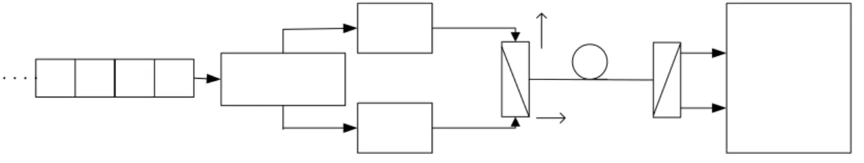
The second topic we are interested is the increase of transmission capacity by polarization diversity technique. This technique transmits simultaneously two data symbols in the two orthogonal polarizations of one wavelength. By taking advantage of the fact that in single-mode fibers, two orthogonally polarized lights will maintain their orthogonality during propagating. To be more specific, under first-order PMD assumption, the SOPs of different input lights will maintain their SOP relationship. Theoretically this can double the data rate in spite of the existence of PMD effects. Figure 6 shows the block diagram of the proposed transmission diversity scheme. The data sequence to be transmitted is split into two subsequences bit by bit. One is called S1 and the other S2 respectively. These two sequences are synchronized and transmitted by two separate transmitters and combined optically by a polarization beam
combiner (PBC) to form different SOP at the fiber input. At the receiver, the combined light after propagating through the fiber is split by a polarization beam splitter (PBS). The two outputs are fed into the decision block and the output SOPs are analyzed and determined.
Figure 6. Block diagram of the transmission diversity scheme.
The detection process is initialized by sending a pilot sequence: 00|10|01|11, which covers all possible (S1, S2) combinations. The decision block will record the output SOPs corresponding to each (S1, S2) combinations and translate them into Jones vectors J1~J4, respectively. Following the pilots, the data sequence is transmitted. As described above, the sequence is split and one pair of bits forms a symbol in this case. At the receiver, the output SOPs of the transmitted symbols will also be converted to Jones vectors. The receiver determines if the output SOP is J1, J2, J3, or J4 by the maximal likelihood algorithm. The preliminary study of this topic is summarized and submitted to OPT2005 [14]. The OPT2005 paper will also be attached as an annex of this report.
V. CONCLUSIONS
In the first part of our work, we have characterized the necessary components and constructed a central node for passive optical ring (POR) network. In the second part of our work, we have studied different pumping schemes and system impairments of Raman amplifiers. We have also developed a design and simulation tool based on Raman rate equations, and used a system simulation tool verify the amplifier performance. In the third part of our work, we studied two other optical network related topics. First, we optimized the dispersion profile for wavelength converters based on parametric amplification. We also systematically studied the stability of gain-flatness of hybrid-OPAs, which can also be used for wavelength converter. Second, we studied a potential capacity enhancement technique by transmission diversity using different polarization states.
We will continue the above work for the second year.
REFERENCES
(參考文獻)
[1] C. R. S. Fludger, V. Handerek, and R. J. Mears, J. Lightwave Technol. 19. 1140-1148 (2001) [2] Y. Chen, A. Singh, L. Lunardi, S. Lumish, M. Achtenhagen, R. Singh, and D. Inniss,
ECOC2001, Tu.L.3.4, Amsterdam, The Netherlands (2001).
[3] D. F. Grosz, A. Kung, D. N. Maywar, L. Altman, M. Movassaghi, H. C. Lin, D. A. Fishman, and T. H. Wood, ECOC2001, Th.B.4.5, Amsterdam, The Netherlands (2001).
[4] J.-C. Bouteiller, K. Brar, S. Radic, J. Bromage, Z. Wang, and C. Headley, “Dual-order Raman pump providing improved noise figure and large gain bandwidth,” Optical Fiber Communication
Conference and Exhibit 2002, Paper FB3, March 17-22, 2002.
[5] J. Bromage, “Raman amplification for fiber communications systems,” J. Lightwave Technol., vol. 22, no. 1, pp. 79-93, Jan. 2004.
[6] S. Kado, Y. Emori, S. Namiki, N. Tsukiji, J. Yoshida, and K. Toshioet, “Broadband flat-noise Raman amplifier using low-noise bi-directionally pumping sources,” ECOC 2001 Proceedings, vol. 6, pp. 38, Amsterdam, Setp. 30-Oct. 4, 2001.
comparison to raman amplified transmission with raman fiber lasers as first-order and second-order pump” Optical Fiber Communication Conference, 2005, Technical Digest
OFC/NFOEC2005, vol. 4, pp. 146-148, Anaheim, CA, March 6-11, 2005.
[8] P. J. Winzer, J. Bromage, R. T. Kane, P. A. Sammer, and C. Headley, “Temporal gain variations in time-division multiplexed Raman pumping schemes,” in Proc. Conf. Lasers and Electro-Optics, CLEO 2002, pp. 428–430, 2002.
[9] J. Bromage, P. J. Winzer, L. E. Nelson, M. D. Mermelstein, C. Horn, and C. H. Headley, “Amplified spontaneous emission in pulse-pumped Raman amplifiers,” IEEE Photon. Technol.
Lett., vol. 15, no. 5, pp. 667–669, May 2003.
[10] L. F. Mollenauer, A. R. Grant, and P. V. Mamyshev, “Time-division multiplexing of pump wavelengths to achieve ultrabroadband, flat, backward-pumped Raman gain,” Opt. Lett. Vol. 27, no. 8, pp. 592-594, Aug. 2002.
[11] M. Du, L. E. Nelson, and P. B. Gaarde, “Investigation of cross gain modulation in 200-km raman amplified spans with Bi-directional pumping,” Optical Fiber Communication Conference,
2005, Paper OWA3, March 6-11, 2005.
[12] P.-C. Liao and M.-C. Ho, “Design and optimization of parametric wavelength converters based on nonlinear dispersion-flattened fibers with two zero-dispersion wavelengths” Pacific
Rim Conference on Lasers and Electro-Optics 2005, July 11-15, 2005, Tokyo, Japan.
[13] P.-C. Liao, Analyses and applications of supercontinuum generation and parametric process in nonlinear optical fibers, a master’s thesis submitted to National Taiwan University.
[14] W. Kuo and M.-C. Ho “A Transmission Diversity Technique Using Different States of Polarization” submitted to OPT 2005, Tainan, Taiwan.
SELF-EVALUATION
(計畫成果自評)
As stated in the proposal, the research goals of this sub-project and the integrated project are:
(i) To investigate the building blocks in the central node of a POR network.
(ii) To study methods to optimize the performance of a central node in order to support longer reach, higher capacity, and more dynamic traffic.
(iii) To demonstrate a working POR network specifically designed for densely populated cities. (iv) To study various protection schemes and the way to implement them in a POR network test-bed.
Our first part of work partially fulfills goal (i) and (iii). Our second part of work fulfills goal (ii). The work is still on-going. We have initialed tasks for (iv), the results will be included in the report of next year.
In conclusion, we have fulfilled the goals of this project. The work is still on-going and we will publish related results in the international journals in the future.
![Figure 5 shows our simulation result. The results are consistent with the experimental data from [11]](https://thumb-ap.123doks.com/thumbv2/9libinfo/8773532.213069/9.892.270.643.402.617/figure-shows-simulation-result-results-consistent-experimental-data.webp)