Sheathless Capillary Electrophoresis/Electrospray
Mass Spectrometry Using a Carbon-Coated
Tapered Fused-Silica Capillary with a Beveled
Edge
Yan Zin Chang, Yet Ran Chen, and Guor Rong Her*
Department of Chemistry, National Taiwan University, Taipei, Taiwan, R.O.C.
A tapered capillary tip containing a beveled edge was developed for use in sheathless capillary electrophoresis/ electrospray mass spectrometry (CE/ESI-MS). The opti-mal flow rate of a 75-µm-i.d., 90-µm-o.d. beveled tapered capillary tip was similar to a conventional flat tapered tip with a 25-µm orifice. Using a mixture of coptisine, berberine, and palmatine chloride, the sheathless CE/ ESI-MS sensitivity of a beveled 75 µm tapered tip capillary was found to be similar to a 25 µm flat tip. Although both tips offer similar CE/ESI-MS sensitivity, the beveled tapered capillary tip is more rugged and durable than a conventional 25-µm tapered capillary because of the larger outside diameter and inside diameter. To make electrical contact, the capillary tip was smeared with paint marker followed by the application of a carbon coating using a graphite pencil. Using this refined carbon-coating procedure, the capillary tip can be operated with aprotic solvents.
The combination of liquid-based separation systems and mass spectrometry (MS) has great potential, because it brings together
efficient separation with selective mass identification1. Because
of its fast, highly efficient separations using extremely small sample quantities, one of most powerful areas of electrospray ionization mass spectrometry (ESI-MS) interfacing is with capillary
electrophoresis (CE).2-4Furthermore, the low quantity of solvents
and chemicals associated with CE results in reduced contamina-tion of the MS ion source.
A major challenge to the use of ESI-MS as an on-line detector for CE separation is the provision of an electrical contact at the capillary outlet. CE/ESI-MS interfacing is most commonly achieved with a liquid sheath, as first demonstrated by Smith and
co-workers.5 The liquid sheath interface is the most widely used
because of its relative ease of implementation and versatility. The
sheath liquid provides electrical contact with the outlet end of
the separation capillary, which improves electrospray stability5and
allows CE/ESI-MS operation over a wide range of buffer
condi-tions.6,7Although the sheath liquid has facilitated progress in CE/
ESI-MS, it clearly has limitations. The addition of makeup liquid in the interface may degrade the overall sensitivity, because the analyte band is diluted in a relatively large volume prior to being dispersed into a fine aerosol mist. More recently, the development
of sheathless CE/ESI-MS interface8-10has attracted significant
attention. In this interface, a conductive capillary tip is employed to eliminate the requirement for a liquid sheath to maintain the continuity of the electrophoresis circuit and simultaneously to provide conditions that are conducive to the formation of charged droplets. In principle, the interface is the simplest for coupling CE to nano- or microelectrospray. This combination leads to high ionization efficiency and low mass detection limits.
In sheathless CE/ESI-MS, the production of a stable spray with high ionization efficiency from the column tip requires critical adjustment of the orifice diameter and field strength applied at the column tip for a given electroosmotic (EOF) flow rate. The sensitivity of sheathless CE/ESI-MS is increased by decreasing the orifice size of the CE column. Decreasing the orifice size also reduces the minimum requirement for flow rate to make the MS a concentration detector. However, the susceptibility to breaking or clogging of the tip during the coating or cleaning procedure limits the application of tapered tips having small insidiameter orifices in the sheathless interface. Furthermore, de-creasing the tip orifice diameter reduces the EOF, thus prolonging the migration time, and influences the overall CE/ESI-MS
sensitivity.11
In this paper, a sheathless CE/ESI-MS was operated using a beveled emitter without decreasing the tip diameter. This tip was coated with carbon using a modified carbon-coating procedure. The fabrication, properties, and application of the beveled tip for sheathless CE/ESI-MS interface are discussed.
* To whom correspondence should be addressed. Tel: (886) 2-23690152, ext. 109. Fax: (886) 2-23638058.
(1) Beale, S. C. Anal. Chem. 1998, 70, 279R-300R.
(2) Olivares, J. A.; Nguyen, N. T.; Yonker, C. R.; Smith, R. D. Anal. Chem. 1987, 59, 1230-1232.
(3) Smith, R. D.; Olivares, J. A.; Nguyen, N. T.; Udseth, H. R. Anal. Chem. 1988, 60, 436-441.
(4) Henion, J. D. Anal. Chem. 1997, 69, 2901-2907.
(5) Smith, R. D.; Barinaga, C. J.; Udseth, H. R. Anal. Chem. 1988, 60, 1948-1952.
(6) Chu, Y. H.; Dunayevskiy, Y. M.; Kirby, D. P.; Vourous, P.; Karger, B. L. J. Am. Chem. Soc.1996, 118, 7827-7835.
(7) Nashabeh, W.; Greve, K. F.; Kirby, D.; Foret, F.; Karger, B. L.; Reifsnyder, D. H.; Builder, S. E. Anal. Chem. 1994, 66, 2148-2154.
(8) Whal, J. H.; Gale, D. C.; Smith, R. D.; J. Chromatogr. 1994, 659, 217-222. (9) Kriger, M. S.; Cook, K. D.; Ramsey, R. S. Anal. Chem. 1995, 67, 385-389. (10) Whal, J. H.; Smith, R. D. J. Capillary Elecrophor. 1994, 1, 62-71. (11) Ding, J.; Vouros, P. Anal. Chem. 1999, 378, 378A-385A. Anal. Chem.2001,73,5083-5087
10.1021/ac010429o CCC: $20.00 © 2001 American Chemical Society Analytical Chemistry, Vol. 73, No. 21, November 1, 2001 5083
Downloaded by NATIONAL TAIWAN UNIV on July 31, 2009
EXPERIMENTAL SECTION
Reagents and Materials. Berberine chloride, palmatine chloride, and 2-(N-cyclohexylamino)ethanesulfonic acid (CHES) were purchased from Sigma (St. Louis, MO). Reserpine was purchased from Acros Organics (Geel, Belgium). Coptisine chloride was obtained from Nacalai Tesque (Kyoto, Japan). Methanol of HPLC grade was purchased from J. T. Baker (Phillipsburg, NJ) and used without further purification. Deionized water (Milli-Q water system, Millipore Inc., Bedford, MA) was used in the preparation of the samples and buffer solution. All fused-silica capillaries were purchased from Polymicro Technolo-gies (Phoenix, AZ). Graphite pencil (Faber-Castello Corp, Ger-many) and paint marker pens (Sakura Color Products Co., Japan) were used directly without any alteration.
Instrumentation. Figure 1 depicts the sheathless CE/ESI-MS instrumentation, which was configured in-house. Briefly, the setup consisted of a 1000 R high-voltage power supply (Spellman, Plainview, NY) connected to a platinum electrode in a vial containing CE buffer and operated at constant-voltage mode. All mass spectrometry experiments were conducted on a LCQ ion-trap mass spectrometer (Finnigan MAT, San Jose, CA). A commercial manipulation stage for the LCQ API source (Protana Co., Odense, Denmark) was used for sheathless CE/ESI-MS operation. This stage can be manipulated in the x, y, and z directions via the micrometer screws. The carbon-coated capillary was inserted into a 22-gauge stainless steel needle for electrical contact and positioned at a distance <2 mm from the entrance hole of the heated transfer capillary. A nebulization gas was not necessary, and the heated transfer capillary was kept at a
temperature of 200 °C. CE/ESI-MS electropherograms were
acquired in selected ion monitoring (SIM) mode.
For direct infusion experiments, the solution was supplied to the capillary tip using a 74900 series syringe pump (Cole-Parmer,
Vernon Hill, IL) with a gastight 10-µL syringe (Hamilton, Reno, NV). Mass spectra were obtained by averaging over 30 scans, and each scan was built up from three microscans using a maximum injection time of 200 ms. For the carbon-coated capillary tip, ESI voltage ranged from 1 to 2 kV.
The sheathless CE/ESI-MS separations were achieved by
applying 20 kV to the injection end of the column and∼1.2 kV to
the electrospray tip. The separation buffer was 0.1% (v/v) acetic acid in 20% methanol solution. The sample was introduced hydrodynamically into the CE capillary (15 mbar; 10 s). The
injected volume was calculated to be∼5.5 nL. To avoid adsorption,
the capillary needs to be washed between analyses. The capillary was washed with 0.1 M NaOH, followed by water and running
buffer. After rinsing, the capillary tube was equilibrated for∼5
min before loading the sample.
The CE-UV system was equipped with a fused-silica capillary of 365-µm o.d. and 75-µm i.d.. The capillary was 90 cm in total length, with an effective length of 80 cm. The detector (UV-C, Rainin, Emeryville, CA) wavelength was set to 254 nm. A high-voltage power supply (Glassman, Whitehouse Sattion, NJ) with 0-30 kV range, was used to apply voltage across the capillary columns. Electroosmotic flow (EOF) was calculated from the observed migration time of an uncharged solute, such as acetone. For study of the spray, the experiments were performed off-line and were observed under a transparent optical microscope
(8×) (Castor, CA) equipped with a video CCD camera. The video
signal was captured by a PC video capture card (C210, Tekram,
Taiwan). The counter electrode for ES was placed∼2 mm from
the tapered tip.
Preparation of the Beveled Tapered Capillary Tip. Briefly, the capillary was drawn manually using a vertically suspended section of capillary to which a small weight (45 g) had been Figure 1. Schematic representation of the sheathless CE/ESI-MS interface.
Downloaded by NATIONAL TAIWAN UNIV on July 31, 2009
attached. The capillary was slowly heated to the melting stage and then quickly withdrawn. This tapered tip was etched in 48% HF for a duration of 15 min. The dimension of the tip was about 90-µm o.d. and 75-µm i.d. before grinding to a beveled tip.
A beveled edge capillary tip can be prepared manually using sandpaper or with a rasp. Between these two, the rasp is a better tool because, unlike the sandpaper, the rasp does not block the tube by leaving sandy residues. The tip was wrapped with
cellophane adhesive tape and then ground to an angle of∼45°.
After grinding, the tape was removed from the tip and the beveled capillary tip was smeared with paint marker pen followed by the application of a carbon coating using a graphite pencil. A photo-graph of the carbon-coated beveled tip is shown in Figure 2. RESULTS AND DISCUSSION
Effect of the Capillary Tip Orifice. When constructing a sheathless interface for CE/ESI-MS, it is important to understand the influence of flow rate on sensitivity. The relationship between intensity of the ion signal and the flow rate under ESI has been
reported.12-14There is a minimum flow rate. Below the minimum
flow rate, no signal can be observed. Above the minimum flow rate, the higher the flow rate, the higher the signal, and the interface behaves more like a mass sensitive detector. As the flow rate increases to a point that the ion intensity reaches a plateau, the interface acts as a concentration-sensitive detector. For optimized CE/ESI-MS measurement, the plateau region of the flow should be used.
As the orifice of the capillary tip decreases, the optimized flow rate also decreases. In other words, the smaller the inside diameter of the capillary tip, the lower the flow rate that is required to achieve the plateau region. For a 75-µm-i.d. orifice tip, the minimum flow rate to reach the plateau region is about 1000 nL/ min. However, for the conventional CE operation, the flow rate is
about 100∼300 nL/min. Thus, to achieve optimal sheathless CE/
ESI-MS operation, it is necessary to decrease the inside diameter of the tip orifice. However, if the tip orifice is decreased too much, several practical problems arise. First, the capillary can easily be
blocked during capillary cleaning or the hydrodynamic injection process. Second, more attention should be paid to the process of conducting coating to prevent clogging the capillary. Furthermore, a small orifice reduces the EOF, thus prolonging the overall migration time. Hence, ESI sensitivity is not the only consideration in selection of the tip orifice. Ease of use and reasonable migration time should also be considered.
Optimal Flow Rate with Different Tips. In our laboratory, it was observed that the optimal flow rate was not only sensitive to the tip diameter, but also to its shape. A plot of ion intensity versus flow rate is shown in Figure 3 for continuous infusion of a 1 ppm reserpine solution using different tips. For a 25-µm flat tip at a flow rate below 200 nL/min, the MS detector was flow-sensitive (Figure 3a). The signal exhibited a plateau in the range of 200-500 nL/min, thus achieving a concentration-sensitive response. This flow rate was compatible with the flow rate of CE. Thus, with a 25-µm tip, the optimal sensitivity can be obtained if the CE flow rate is >200 nL/min. However, for a 75-µm flat tip, no plateau region was observed at a flow rate of up to 500 nL/ min (Figure 3b). In this case, the MS behaved as a flow-sensitive detector. The plateau region was obtained when the flow rate increased to 1000 nL/min (data not shown). This optimal flow (12) Bateman, K. P.; White, R. L.; Thibault, P. Rapid Commun. Mass Spectrom.
1997, 11, 307.
(13) Alexander, J. N., IV; Schultz, G. A.; Poli, D. A. Rapid Commun. Mass Spectrom.1998, 12, 1187.
(14) Barroso, M. B.; de Jong, Ad P. J. Am. Soc. Mass Spectrom. 1999, 10, 1271-1278.
Figure 2. Photograph of a carbon-coated bevel-tapered tip.
Figure 3. Ion intensity versus flow rate of infusion solution (1 ppm respine in MeOH:H2O)4:1+0.1% acetic acid) using a (a) 25-µm flat, a (b) 75-µm flat, and a (c) 75-µm beveled tip.
Downloaded by NATIONAL TAIWAN UNIV on July 31, 2009
rate is incompatible with the flow rate of CE; thus, the sensitivity cannot be optimized when a 75-µm flat tip is used.
When a 75-µm flat tip was ground to a beveled tip, it was found that the plateau region was similar to a conventional 25-µm flat
tip (Figure 3c); both the 75-µm beveled and the 25-µm flat tip
reached the plateau region at a flow rate of∼200 nL/min. Because
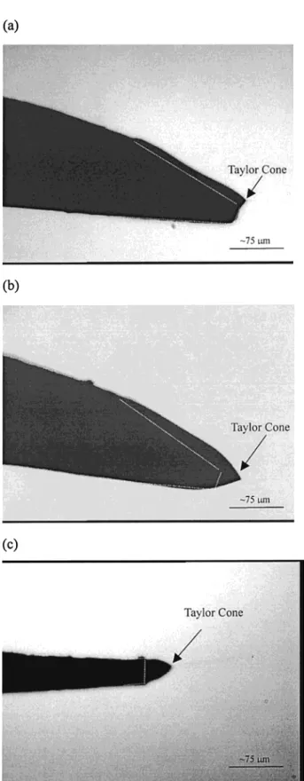
the optimum flow rate is similar, the sensitivity of a 75-µm beveled and a 25-µm flat tip should also be similar. Although the 25-µm flat tip and the 75 µm beveled tip may have similar sensitivity due to the size of orifice, the 75-µm beveled tip should be more rugged and durable than the 25-µm flat tip. Moreover, because the orifice inside diameter is the same as the inside diameter of the CE column, a 75-µm tip presents no restriction to the EOF, which is in contrast to a 25-µm tip. Thus, from a practical point of Figure 4. Photographs of Taylor cone produced from (a) a 75-µm
beveled tip at 400 nL/min, (b) a 75-µm beveled tip at 1000 nL/min, (c) a 25-µm flat tip at 400 nL/min of MeOH:H2O)4:1+0.1% acetic acid. The dashed lines represent the edge of the capillary tip. The dashed lines in Figure 4a,b were drawn by comparing the images with Figure 2.
Figure 5. Sheathless CE/ESI-MS electropherograms obtained from (a) a 25-µm flat, (b) a 75-µm flat, and (c) a 75-µm beveled tip.
Downloaded by NATIONAL TAIWAN UNIV on July 31, 2009
view, a 75-µm beveled tip presents a better alternative than a
25-µm flat tip.
Taylor Cone of the Beveled Tip. The similarity in optimal flow rate between a 75-µm beveled and a 25-µm flat tips suggests that the shape of the tip plays an important role in electrospray ionization. To understand this phenomenon, the Taylor cone of the beveled tip was investigated under a microscope. Figure 4a,b shows the photographs of Taylor cone that were produced from a 75-µm beveled tip. At a low flow rate, the Taylor cone was produced from the apex of the beveled tip (Figure 4a) and was stable, even at a flow rate below 100 µL/min. The volume of the liquid at the bevel tip was similar to the one produced from a 25-µm flat tip. When the flow rate was increased, the size of the Taylor cone was gradually increased (Figure 4b). The flow rate
can be increased to∼3 µL/min without any liquid accumulation.
The beveled tip can be operated at a wide range of flow rates, because the Tayler cone of the beveled tip is stable at both low and high flow rates.
Coating of the Beveled Tip with Carbon. Recently, we showed that a carbon-coated capillary is useful for microspray and
sheathless CE/ESI-MS applications.15 The capillary tip was
smeared with a marker pen followed by carbon coating using a soft pencil. The carbon coating method is simple, rapid, and less expensive than the preparation of gold-coated capillaries; however, the carbon-coated tip is not recommended for work with solutions containing more than 60% methanol because of the dissolution of marker pen layer. To overcome this difficulty, a paint marker pen was used to replace the conventional marker pen. In the modified carbon-coated process, the capillary tip was smeared with paint marker pen, followed by carbon coating using a graphite pencil. Because it contains an oil-based resin, the paint layer rigidly adheres to the silica. The layer was found to be stable under organic solvent such as methanol or acetonitrile. Recently, an alternative emitter coating using polyaniline has been described
that also shows some stability to organic solvent.16
Application of the Bevel-Tapered Tip Capillary to Sheath-less CE/ESI-MS. The formation of a stable Taylor cone from which electrospray emission can be obtained requires a delicate
balance between the EOF and the rate of ionization/desolvation. The EOF of a 75-µm-i.d. column was measured by injection of acetonitrile using UV as the detector. The EOF was determined
to be∼250 µL/min (data not shown) and was in the plateau region
of a 25-µm flat tip or a 75-µm beveled tip (Figure 3a,c). The mass electropherograms obtained from CE capillaries when using different tapered tips are shown in Figure 5. These electropherograms were acquired in SIM mode using a mixture of berberine, coptisine, and palmatine. CE/ESI-MS using a
25-µm-i.d. flat tip capillary yielded analyte response (Figure 5a) an
order higher than that obtained using a 75-µm i.d. flat tip capillary (Figure 5b). On the other hand, as expected, the sensitivity obtained with a 75-µm beveled tip (Figure 5c) was similar to that obtained with a 25-µm flat tip. The resolution obtained with a
75-µm beveled tip (Figure 5c) was also similar to that of a 25-75-µm flat
tip (Figure 5a). This is most likely due to the fact that the mixing volume at the emitter tip of a 75-µm beveled tip (Figure 4a) is similar to that of a 25-µm flat tip (Figure 4c).
CONCLUSION
The sensitivity of a 75-µm-i.d. beveled tip is similar to a conventional 25-µm-i.d. flat tip. However, the beveled tip is more rugged and durable than a flat tip because of larger inside and outside diameters. Furthermore, unlike the smaller inside diam-eter tips, larger inside diamdiam-eter tips do not present a restriction to the EOF, which results in shorter analysis times. The beveled tip was coated with carbon using a modified carbon-coating procedure. This coating was found to be stable under aprotic solvents. Work is in progress to investigate the behavior different angles on the beveled tip. It is hoped that with more knowledge about the shape of the capillary tip, a better interface can be developed.
ACKNOWLEDGMENT
We thank the National Science Council of the Republic of China for financial support.
Received for review April 16, 2001. Accepted July 27, 2001.
AC010429O (15) Chang, Y. Z.; Her, G. R. Anal. Chem. 2000, 72, 626-630.
(16) Maziarz, E. P., III.; Lorenz, S. A.; White, T. P.; Wood, T. D. J. Am. Soc. Mass Spectrom.2000, 11, 659-663.
Downloaded by NATIONAL TAIWAN UNIV on July 31, 2009