Institute of Electronics Engineering Hsinchu, 30010, Taiwan, R.O.C Huang-Cheng Chiang
Industrial Technology Research Institute Hsinchu, 30010, Taiwan, R.O.C
Sheng-Jyh Wang
National Chiao Tung University Institute of Electronics Engineering Hsinchu, 30010, Taiwan, R.O.C
our approach, 1-bit gray-coded bit-plane block matching, instead of 8-bit gray-level block matching, is used to greatly simplify the computation of motion estimation. This computation saving makes possible a finer divi-sion of image frame and thus facilitates the employment of a much more robust procedure for motion decision. To deal with various interfering factors in motion estimation, the temporal information of each local mo-tion vector is also used to efficiently distinguish random-like movement from temporally correlated movement. To compensate for camera rota-tion, an affine model is used in the motion compensation unit without adding too much computation load. Having considered both program-ming flexibility and hardware efficiency, the motion decision unit and the motion compensation unit are coded in a microprocessor that intercon-nects with the stabilization hardware, which consists of the motion esti-mation unit and the digital zooming unit. A slightly simplified version of the proposed stabilizer is implemented on a field programmable gate array (FPGA) board. © 2001 Society of Photo-Optical Instrumentation Engineers. [DOI: 10.1117/1.1405415]
Subject terms: digital image stabilization; motion estimation; digital camcorder; gray-coded bit-plane.
Paper PT-002 received Nov. 30, 2000; revised manuscript received Feb. 10, 2001; accepted for publication Feb. 21, 2001.
1 Introduction
Recently, more and more video cameras include compact size and powerful zooming capability. The advancement of these features makes the image stability problem even more crucial, because an unconscious movement of the holding hand may cause a dramatic shaking of the images. As a consequence, an image stabilization system is usually re-quired to relieve the problem. Among various types of sta-bilization systems, a digital image stasta-bilization共DIS兲 sys-tem, which can be fully realized in very large scale integration共VLSI兲, could be a more appropriate solution to fit the compactness requirement. So far, many approaches regarding DIS have been proposed and some of them have already been implemented in commercial video cameras.
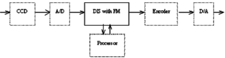
Figure 1 shows a typical structure of a digital video camera, equipped with a DIS system and a corresponding frame memory1共FM兲. The FM is used to store current im-age data and to output the stabilized imim-age data. In general, as shown in Fig. 2, a DIS system usually includes five major units:共1兲 preprocessing unit, 共2兲 a motion estimation unit,共3兲 a motion decision unit, 共4兲 a motion compensation unit for FM, and共5兲 a digital zooming unit.2
A traditional way to do motion estimation is to use block-matching methods.1–7To reduce computational com-plexity, these block-matching methods usually divide an
image into a small number of blocks and select some rep-resentative points to calculate the motion vector of each block. Then, these block motion vectors are utilized to-gether to estimate the global motion vector to compensate the movement of the whole image. Even though this coarse-division strategy can save a huge amount of compu-tation, the rough division of an image may cause the loss of local information and reduce the precision in global motion decision. Without decreasing too much accuracy in motion estimation, Lee et al. proposed in Refs. 8 and 9, respec-tively, the usage of bit-plane and gray-coded bit-plane to do block matching. Even though this approach has greatly re-duced the computation complexity, their algorithms are still based on some traditional methods for block division, mo-tion decision, and momo-tion compensamo-tion. For these conven-tional methods, only simple strategies can be applied in motion decision and the resulting motion compensation is not very reliable.
In this paper, we also adopt the gray-coded bit-plane strategy to do motion estimation. Under an acceptable in-crease of computation complexity, however, we divide an image frame into finer blocks to do localized block match-ing. This finer division enables a much more accurate esti-mation of the local movement inside the captured frames. Moreover, the increased number of local motion vectors 共LMVs兲 facilitates the employment of a more complex pro-cedure for motion decision. Furthermore, to distinguish the movement caused by camera shaking from the movement caused by moving objects or intentional panning, the tem-This paper is a revision of a paper presented at the SPIE conference on
Input/Output and Imaging Technologies II, July 2000, Taipei, Taiwan. The paper presented there appears共unrefereed兲 in SPIE Proceedings Vol. 4080.
poral correlation of each local motion vector is also care-fully investigated in our DIS system. In motion compensa-tion, an affine model is evaluated to compensate translational and rotatory movements. Beside the software development of the proposed stabilization algorithm, we also implement the motion estimation part in an efficient real-time hardware on a field programmable gate array. 2 Localized Block Matching Over the
Gray-Coded Bit-Plane
Traditionally, operations are applied directly on 8-bit gray-level images to do image stabilization. The involved 8-bit operations, especially the 8-bit block matching in motion estimation, result in a heavy computational load for real-time hardware implementation. In 1998, Ko et al. proposed the usage of bit-planes in image stabilization.8 With bit-planes, the block matching process can be implemented using only binary Boolean operations and the computation complexity of motion estimation can be significantly re-duced without sacrificing too much motion estimation per-formance. In 1999, Lee et al. proposed the usage of gray-coded bit-planes to further improve the accuracy of local motion vectors.9 In this paper, we also adopt gray-coded bit-planes as the basis of motion estimation. Here, assume
f (x, y ) is a gray-level image and is represented as:
f共x,y兲⫽aK⫺1共x,y兲2K⫺1⫹aK⫺2共x,y兲2K⫺2⫹¯
⫹a1共x,y兲2⫹a0共x,y兲. 共1兲
Then, the gray-coded bit-planes are defined as:
gi共x,y兲⫽ai共x,y兲丣ai⫹1共x,y兲, 0⭐i⭐K⫺2, 共2兲
and
gK⫺1共x,y兲⫽aK⫺1共x,y兲.
Figure 3 shows the comparison between bit-planes and gray-coded bit-planes. We can easily see that either the fifth to seventh planes or the fifth to seventh gray-coded bit-planes can roughly catch the spirit of image contents, but the gray-coded bit-planes tend to have less intensity fluc-tuation. In this paper, we work on the fifth or the sixth gray-coded bit-planes to do motion estimation and the in-volved correlation measure is defined as:
Fig. 2 General structure of DIS system with FM.
c共m,n兲⫽ 1 M N x
兺
⫽0 M⫺1兺
y⫽0 N⫺1 gkt共x,y兲丣gkt⫺1共x⫹m, y⫹n兲. 共3兲To improve the motion estimation accuracy, we apply a finer division over the gray-coded bit-planes. In Fig. 4, we demonstrate the comparison of a traditional rough-division method versus our fine-division method. Since the opera-tions over gray-coded bit-planes are much simpler than the operations over 8-bit gray-level images, the computation complexity of our fine-division 1-bit gray-coded bit-plane approach is roughly the same as the traditional coarse-division 8-bit gray-level image approach.
The image in Fig. 5 is a frame extracted from an image sequence, which is captured by an intentionally shaken video camera. The scene in this image sequence contains a moving object, which is moving to the right. The traditional coarse division method divides this frame into four blocks and detects four local motion vectors separately:共4,0兲, 共⫺1, ⫺6兲, 共⫺5,1兲, and 共⫺2,2兲 关see Fig. 5共a兲兴. Three of these four LMVs, except the lower-right LMV, are not reliable due to either lack of features or the presence of repeated patterns. The lower-right LMV, on the other hand, is also biased due to the existence of a moving object within that block. Therefore, for this image sequence, we could hardly detect the actual movement caused by the shaking video camera. As a comparison, with the proposed fine-division approach, plus some motion decision strategy that is mentioned later, there are many LMVs that may still indicate the movement of the video camera关as shown in Fig. 5共b兲兴.
With the fine-division approach, the presence of some moving objects in the image frame will have less impact on the accuracy of global motion estimation. Moreover, the increased amount of motion vectors also increases the ro-bustness of motion decision. Regarding the choice of block size, it is actually a trade-off issue. If the block size is too small, the accuracy of motion estimation is decreased; while if the block size is too large, some local information
will get lost. Consequently, for a practical camera system, we empirically choose the block size to be 64⫻64 and divide each frame into 24 regions, as shown in Fig. 6. Moreover, since the core operation in block matching is actually the XOR operation on binary images, we adopt the full search approach with the search range being⫾14. 3 Motion Decision
Many factors exist that can affect the accuracy and perfor-mance of motion estimation, which we call ‘‘interfering factors.’’ Among these factors, lack of features, existence of repeated patterns, existence of moving objects, intentional panning, intentional zooming, and low SNR are most com-mon. Many methods for detecting these factors have al-ready been proposed.1,3,4,10 However, these methods may not be suitable for our architecture and we design our own approach to detect these factors for localized block match-ing over gray-coded bit-planes.
3.1 Lack of Features
Lack of feature in a block means the image content in that block does not have enough features to characterize mo-tion. In this case, the estimated LMV for that block is not reliable and should not be used for global motion compen-sation. To detect the occurrence of lack of feature, we check the correlation value c(m,n), which has been de-fined in Eq.共3兲 for each block. The average correlation Cave and the minimum correlation Cminare defined as:
Cave⫽ 1 共2P⫹1兲共2Q⫹1兲m
兺
⫽⫺P P兺
n⫽⫺Q Q c共m,n兲, 共4兲 and Cmin⫽min m,n c共m,n兲, 共5兲where m苸关⫺P,P兴 and n苸关⫺Q,Q兴 are the indices of the search neighborhood in the horizontal and vertical direc-tions. For a lack-of-feature block, the correlation values for different共m,n兲 would be very similar. Hence, as the differ-ence between Cave and Cmin is smaller than a predefined threshold, we declare that this block is lack of features and the estimated LMV is invalid.
3.2 Existence of Repeated Patterns
If a block contains repeated patterns, the similarity of im-age content due to the repeated patterns may cause a
mis-Fig. 4 (a) Coarse division versus (b) fine division.
Fig. 5 (a) Coarse division of image and the detected LMVs and (b)
fine division of image and the valid LMVs.
Fig. 6 Illustration of the division of the gray-coded bit-planes in our
judgment of motion estimation. This problem becomes more serious when the block matching process is localized. To detect the occurrence of repeated patterns, we also check the correlation value c(m,n) in block matching. If there is a repeated pattern, the first minimal correlation value C1st-min and the second minimal correlation value
C2nd-min are usually very similar. A simple thresholding mechanism can thus be applied on each block to detect the existence of repeated patterns.
3.3 Existence of Moving Objects
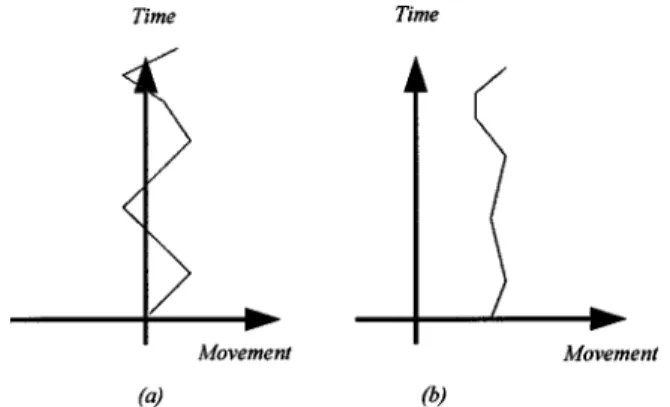
If an image sequence contains a moving object, the regions including this moving object may offer incorrect LMVs. We must eliminate these invalid LMVs to ensure the accu-racy of motion compensation. Here, we propose a new ap-proach, which is efficient and can be easily implemented for the detection of moving objects. First, we present the difference between two major types of motion: random-like motion and temporally correlated motion. As shown in Fig. 7共a兲, a motion regarded as random-like will fluctuate around zero and the variance of this motion is usually large. On the other hand, Fig. 7共b兲 shows a temporally correlated motion, which usually moves in a specific direction and the variance of this motion is usually small.
These two types of motion are closely related to the motion caused by hand shaking and the motion caused by moving objects or intentional panning. The motion caused by hand shaking causes the captured scene to fluctuate around the center of focus, which causes the motion vectors to fluctuate around zero. On the other hand, the movement caused by moving objects or intentional motion tends to move in the same direction for a short time. Consequently, we can classify the motion caused by hand shaking as random-like motion and the motion caused by moving ob-jects or intentional panning as temporally correlated mo-tion. Based on this observation, we design a simple test, as shown next, to distinguish these two kinds of motion: 兩LMV共t1兲⫺LMV共t2兲兩⫹兩LMV共t2兲⫺LMV共t3兲兩⫹¯ ⫹兩LMV共tN⫺1兲⫺LMV共tN兲兩⫽T1, 共6兲 1 N
兺
i⫽1 N LMV共ti兲⫽T2. 共7兲If T1/T2⬍K1 and T2⬎K2, then it is temporally correlated motion; otherwise it is random-like motion.
Given a block, we observe its LMV along the temporal domain. Assume LMV(ti) denotes the LMV at time ti. If a motion behaves as temporally correlated motion, T1is usu-ally small and T2 is usually large. After these temporally correlated motion vectors are detected, we use them as clues to detect moving objects. In our simulation, we choose N⫽8, K1⫽5, and K2⫽1. Figure 8 shows the ex-periment result. The test sequence contains two motions: temporally correlated motion at the slider 关Fig. 8共a兲兴 and random-like motion for the remaining parts关Fig. 8共b兲兴. The simulation result demonstrates that these LMVs corre-sponding to temporally correlated motion are correctly de-tected and they are gathering around the slider关as shown in Fig. 8共a兲兴. On the other hand, Fig. 8共b兲 indicates these random-like LMVs. Note that in this example we have al-ready applied the lack-of-feature test to remove some unre-liable LMVs.
If the temporally correlated motion vectors appear to be localized, these motion vectors are treated as being caused by existing moving objects. On the other hand, if the tem-porally correlated motion vectors have a global trend, the camera may be under an intentional panning. This situation is discussed next.
3.4 Intentional Panning
The intentional motion of camcorders, like the motion of panning, may cause a misjudgment of the motion compen-sation. Thus, reliable detection of a panning condition is required in the motion decision unit. As mentioned, tempo-rally correlated movement behaves differently from random-like movement, and we can categorize the motion of panning as temporally correlated. Moreover, even though both intentional panning and the existence of mov-ing objects will cause temporally correlated movement, the occurrence of panning will have a global influence, while the existence of moving objects tends to have a local influ-ence. Hence, in our approach, if more than 80% of the LMVs are detected as temporally correlated, we consider that the camera is under a panning condition and no motion compensation is required. Otherwise, we assume these tem-porally correlated motion vectors are caused by some mov-ing objects in the image and declare these LMVs as invalid.
Fig. 7 Two kinds of motion: (a) random-like motion and (b)
tempo-rally correlated motion.
Fig. 8 Simulation results: (a) temporally correlated LMVs and (b)
3.5 Intentional Zooming
One of the popular functions in digital camcorders is to optically zoom in or zoom out of the scene. When this situation occurs, the motion decision unit should detect it and avoid the misusage of motion compensation. In our DIS system, the local motion vectors are allocated as shown in Fig. 9. To detect intentional zooming, we can check the LMVs at B1, C2, D2, E1, C3, B4, D3, and E4. If these LMVs are detected to have motion vectors pointing along the directions as indicated in Fig. 9, we judge that the camera is under the zoom-in condition and no motion com-pensation is required. In a similar way, we can also detect the occurrence of the zoom-out condition.
3.6 Low SNR
If the SNR of the image content is too small, the accuracy and performance of motion estimation will be affected. Be-sides, some image content, such as a waving sea, may in-troduce an unstable effect on motion estimation. Therefore, we design a noise-level test to check whether the remaining valid LMVs are similar enough to each other. If yes, these valid LMVs could be used to compensate the global move-ment caused by the vibration of video camera; otherwise, these LMVs could be too disordered to be used.
To check the noise level, we compute the variance of these valid LMVs. If the variance is higher than a pre-defined threshold, we regard these LMVs as useless and no motion compensation is made. Moreover, if the number of these valid LMVs is too small, these LMVs might not pro-vide accurate enough information for motion compensa-tion. When this happens, we also disable the use of motion compensation.
Figure 10 shows the procedure adopted in our motion decision unit. Note that the feasibility of this procedure actually comes from the fine-division strategy. Without fine division, the number of LMVs will not be large enough to support these tests. After this motion-decision procedure, we output these valid LMVs, together with the inferred status, to the motion compensation unit.
4 Motion Compensation
After LMVs are detected and verified, these valid LMVs are combined together to estimate the global motion vector for motion compensation. Since the shaking of the camera usually consists of translational movement and rotatory
movement, the affine model is used in this paper to de-scribe the movement of the global motion. Equation 共8兲 shows the equations of affine motion.
再
X¯t⫹1⫽aXt⫹bYt⫹c Y¯
t⫹1⫽dXt⫹eYt⫹ f
, 共8兲
where (X¯ ,Y¯ ) denote the coordinates of the compared frame and共X,Y兲 denote the coordinates of the reference frame.
To estimate the six coefficients 共a to f 兲 in the affine model, we use the least mean squares approach. Assume there are N valid motion vectors. We use the standard op-timization method to find the ‘‘optimal’’ coefficients that minimize the following equations:
兺
n⫽1 N 共aXn⫹bYn⫹c⫺Xn兲2, 共9兲兺
n⫽1 N 共dXn⫹eYn⫹ f ⫺Yn兲2.After some straightforward mathematical deductions, these six coefficients can be calculated by
Fig. 9 Division of image frame and the indicated directions of
mo-tion vectors in the zoom-in condimo-tion.
冋
a b c册
⫽冋
X12⫹X22⫹¯⫹Xn2 X1Y1⫹X2Y2⫹¯⫹XnY X1⫹X2⫹¯⫹Xn X1Y1⫹X2Y2⫹¯⫹XnYn Y1 2⫹Y 2 2⫹¯⫹Y n 2 Y1⫹Y2⫹¯⫹Yn X1⫹X2⫹¯⫹Xn Y1⫹Y2⫹¯⫹Yn n册
⫺1 ⫻冋
X1X1⫹X2X2⫹¯⫹XnXn X1Y1⫹X2Y2⫹¯⫹XnYn X1⫹X2⫹¯⫹Xn册
,冋
d e f册
⫽冋
X12⫹X22⫹¯⫹Xn2 X1Y1⫹X2Y2⫹¯⫹XnY X1⫹X2⫹¯⫹Xn X1Y1⫹X2Y2⫹¯⫹XnYn Y1 2⫹Y 2 2⫹¯⫹Y n 2 Y1⫹Y2⫹¯⫹Y n X1⫹X2⫹¯⫹Xn Y1⫹Y2⫹¯⫹Yn n册
⫺1 ⫻冋
Y1X1⫹Y2X2⫹¯⫹YnXn Y1Y1⫹Y2Y2⫹¯⫹YnYn Y1⫹Y2⫹¯⫹Yn册
. 共10兲It seems, at the first glance, that Eq.共10兲 is a little too complicated for practical implementation. Nevertheless, all the elements in the matrices can be treated as the inner product of two vectors and some of these entries are actu-ally duplicated. This implies that this computation can be efficiently implemented with a fast vector inner product algorithm. Moreover, the involved matrices are only 3⫻3 and their inverses can be easily computed. Based on a soft-ware simulation running on a Pentium III at 450 MHz, the affine coefficients for a single frame can be computed in 5⫻10⫺6s. Figure 11 shows the simulation of motion com-pensation after using the affine model. Figures 11共a兲 and 11共b兲 illustrate two consecutive image frames with a rota-tory motion. Figure 11共d兲 shows the detected local motion vectors after motion estimation and motion decision. Based on these valid motion vectors, we calculate the coefficients of the affine model, and Fig. 11共e兲 shows the stabilized image frame. Figures 11共c兲 and 11共f兲 show, respectively, the intensity difference of the two consecutive frames be-fore and after motion compensation.
Moreover, because we must acquire a stabilized image sequence starting from the first frame till the current frame, we accumulate each frame motion vector共FMV兲 to form an accumulated motion vector 共AMV兲. To suppress error
ac-cumulation and to have a mechanism to slowly pull the focus center back to the frame center, the following equa-tion is used to robustly calculate AMV.
AMV关t兴⫽a⫻AMV关t⫺1兴⫹FMV关t兴. 共11兲
Besides the software simulation of this proposed DIS architecture, a real-time DIS system is also implemented in hardware. Having considered both programming flexibility and hardware efficiency, the motion decision unit and the motion compensation unit are coded in a microprocessor that interconnects with stabilization hardware, which con-sists of the motion estimation unit and the digital zooming unit. The stabilization hardware is now implemented on an FPGA board. Since the microprocessor is still not powerful enough to support affine modeling, the conventional trans-lational modeling is adopted in this real-time hardware simulation.
5 Conclusion
In this paper, we propose a fine-division approach over gray-coded bit-planes to achieve high-performance image stabilization. The usage of gray-coded bit-planes greatly re-duces the computation complexity of motion estimation, while the fine-division approach improves the usability of Fig. 11 (a) Reference frame, (b) current frame, (c) difference between (a) and (b), (d) LMVs, (e) frame
FPGA board for the motion estimation unit together with a microprocessor for the motion decision unit and the motion compensation unit.
References
1. J. K. Paik, Y. C. Park, and D. W. Kim, ‘‘An adaptive motion decision system for digital image stabilizer based on edge pattern matching,’’ IEEE Trans. Consum. Electron. 38共3兲, 607–616 共1992兲.
2. T. Kinugasa, N. Yamamoto, and H. Komatsu, ‘‘Electronic image sta-bilizer for video camera use,’’ IEEE Trans. Consum. Electron. 36共3兲, 520–525共1990兲.
3. K. Uomori, A. Morimura, H. Ishii, T. Sakaguchi, and Y. Kitamura, ‘‘Automatic image stabilizing system by full-digital signal process-ing,’’ IEEE Trans. Consum. Electron. 36共3兲, 510–519 共1990兲. 4. Y. Egusa, H. Akahori, A. Morimura, and N. Wakami, ‘‘An application
of fuzzy set theory for an electronic video camera image stabilizer,’’ IEEE Trans. Fuzzy Syst. 3共3兲, 351–356 共1995兲.
5. Y. Egusa, H. Akahori, A. Morimura, and N. Wakami, ‘‘An electronic video camera image stabilizer operated on fuzzy theory,’’ Proc. IEEE Cont. Fuzzy Syst., 851– 858共1992兲.
6. C. Morimoto and R. Chellappa, ‘‘Evaluation of image stabilization algorithms,’’ Proc. IEEE Conf. Acoustics, Speech, and Signal Process-ing 5, 2789–2792共1998兲.
7. M. Sekine, T. Kondou, and H. Hirose, ‘‘Motion vector detecting sys-tem for video images stabilizers,’’ IEEE Trans. Consum. Electron. 268 –269共1994兲.
8. S.-H. Lee, K.-H. Lee, and S.-J. Ko, ‘‘Digital image stabilizing algo-rithms based on bit-plane matching,’’ IEEE Int’l. Conf. Consum. Elec-tron., 126 –127共1998兲.
9. S.-H. Lee, S.-W. Jeon, E.-S. Kang, and S.-J. Ko, ‘‘Fast digital stabi-lizer based on gray coded bit-plane matching,’’ IEEE Trans. Consum. Electron. 45共3兲, 598–603 共1999兲.
10. J. K. Paik, Y. C. Park, and S. W. Park, ‘‘An edge detection approach to digital image stabilization based on tri-state adaptive linear neurons,’’ IEEE Trans. Consum. Electron. 37共3兲, 521–530 共1991兲.
Technology Research Institute. His re-search interests include digital signal pro-cessing, digital image propro-cessing, and communications.
Huang-Cheng Chiang received his BS,
MS, and PhD degrees from the Depart-ment of Electrical Engineering of Tatung University, Taipei, Taiwan, in 1990, 1992, and 1996, respectively. From October 1996 to 1999 he was a research engineer en-gaged in the development of digital still camera with the Image Technology Depart-ment of Opto-Electronics & System Labo-ratories (OES). He is currently a section manager in OES involved in the research on high definition TV cameras, real-time color imaging, and video signal processing.
Sheng-Jyh Wang received his BS degree
in electronics engineering from National Chiao Tung University, Taiwan, in 1984 and his MS and PhD degrees in electrical engi-neering from Stanford University, in 1990 and 1995, respectively. He is currently an associate professor with the Department of Electronics Engineering, National Chiao Tung University, Taiwan.