行政院國家科學委員會專題研究計畫 成果報告
金屬微成形製程及其應用之研究--子計畫三:純銅微擠製
製程及其應用之研究
研究成果報告(精簡版)
計 畫 類 別 : 整合型 計 畫 編 號 : NSC 98-2221-E-151-002- 執 行 期 間 : 98 年 08 月 01 日至 99 年 07 月 31 日 執 行 單 位 : 國立高雄應用科技大學模具工程系 計 畫 主 持 人 : 張朝誠 計畫參與人員: 碩士班研究生-兼任助理人員:蕭新聖 碩士班研究生-兼任助理人員:羅時治 碩士班研究生-兼任助理人員:林儷伊 報 告 附 件 : 出席國際會議研究心得報告及發表論文 處 理 方 式 : 本計畫可公開查詢中 華 民 國 99 年 10 月 25 日
行政院國家科學委員會補助專題研究計畫
■ 成 果 報 告
□期中進度報告
金屬微成形製程及其應用之研究--子計畫三:
純銅微擠製製程及其應用之研究
計畫類別:□ 個別型計畫
■ 整合型計畫
計畫編號:NSC 98-2221-E -151-002
執行期間:98 年 08 月 01 日 至 99 年 07 月 31 日
計畫主持人:張朝誠
共同主持人:(無)
計畫參與人員:蕭新聖、羅時治、林儷伊
成果報告類型(依經費核定清單規定繳交):■精簡報告
□完整報告
本成果報告包括以下應繳交之附件:
□赴國外出差或研習心得報告一份
□赴大陸地區出差或研習心得報告一份
■出席國際學術會議心得報告及發表之論文各一份
□國際合作研究計畫國外研究報告書一份
處理方式:除產學合作研究計畫、提升產業技術及人才培育研究計畫、列管計畫
及下列情形者外,得立即公開查詢
□涉及專利或其他智慧財產權,□一年□二年後可公開查詢
執行單位:國立高雄應用科技大學 模具工程系
中
華
民
國
九十九 年
十
月 十 日
摘要
金屬微擠製是製造微小化產品所需之微插銷、微扣件與微型杯狀等元件的重要技術。其複雜之成 形行為受晶粒尺寸、溫度、摩擦與潤滑效應等多項因素影響。然而,大部分之研究仍以冷成形或只針 對單一因素之影響進行探討,對於高溫成形與各因素間之交互作用對微擠製之材料流動行為,仍需要 更深入之研究。 本計畫為整合型計畫「金屬微成形製程及其應用之研究」之子計畫二「純銅微擠製製程及其應用 之研究」,其目的在建構一個可控制製程溫度的微擠製實驗平台,並設計與製作微擠製模具,以探討純 銅之製程溫度、晶粒尺寸、胚料表面粗糙度與潤滑條件對微擠製製程之影響。另外,本計畫將以等徑 轉角擠製技術調整純銅之晶粒尺寸至數個微米,探討具有超細晶粒之純銅在微擠製之成形特性,而所 備製之晶粒細化純銅胚料,亦將提供給其它子計畫進行相關之研究。 本計畫之研究工作將以三年時間完成。第一年擬建構可進行溫間成形之微擠製實驗平台,利用等 徑轉角擠製製作晶粒細化之純銅胚料,並以微逆向擠製技術製作微型圓杯,探討製程溫度與晶粒尺寸 對圓杯壁厚與杯緣高度分佈之影響,並歸納此兩參數與材料流動之關係,尋找均質流動的臨界值,以 作為判定有限元素等數值方法可以有效應用於金屬微擠製製程模擬之準則。第二年將採用第一年之研 究成果,利用可獲得均質流動之晶粒尺寸與製程溫度條件,以微雙杯擠製製程與數值模擬,探討胚料 於不同表面粗糙度與潤滑條件對微擠製成形之影響。第三年將根據前二年研究結果所歸納的均質流動 之最佳參數組合,以結合正向與逆向微擠製之產品為例,評估有限元素模擬輔助微金屬元件設計之可 行性,利用數值模擬與實驗驗證,探討成品之尺寸變化對材料流動的影響。 總之,本計畫考慮製程溫度、晶粒尺寸、摩擦與潤滑效應等因素,利用數值模擬與實驗方法,對 純銅微擠製製程進行一系列之研究,不僅深入瞭解金屬材料於微尺度下之流動行為,且提供金屬微型 元件之設計與製作的參考依據,對於如何解決其它的微成形問題,也有進一步的貢獻。 關鍵詞:微金屬成形、微擠製、溫間成形、晶粒尺寸 AbstractMicro-extrusion process plays an important role in manufacturing micro-metal parts, such as micro-pins, micro-connectors and micro-scale cup-shaped parts, which are widely used in micro-products. The process with complicated forming behaviors is affected by many factors including grain size, temperature, friction and lubrication conditions.
Thisproposal,“A study ofmicro-extrusion processesofcopperand itsapplications”,isasub-project under an integrated research project,“A study ofmetalmicro-forming processes and itsapplication”.The aim ofthe proposal is to develop and create a micro extrusion system with temperature control in order to investigate the effects of temperature, grain size, roughness and lubrication on the micro extrusion of copper. To refine the grains in copper to the size of few microns, the equal channel angular extrusion will be employed and studied. The obtained coppers with extra fine grains are used not only in this research work but also for the others in the integrated research project. The proposed research work will be completed in three years. In the first year, a micro extrusion system for warm forming of copper at elevated temperature will be established. Experiments of micro backward extrusion of copper cups will also be conducted to study the effects of temperature and grain size on the materials flow in terms of the distribution of the wall thickness and the rim height of the extruded cups. It is therefore possible to estimate critical values of temperature and grain size for
avoiding process scattering and providing homogeneous flow conditions which are important for applying the finite element simulation in micro metal forming. In the second year, the study will focus on the influence of the roughness and lubrication on the materials flow by conducting micro double cup extrusion and simulations. Based on the results obtained from the previous works, in the last year, a combined micro forward and backward extrusion process will be employed to investigate the possibility of using the finite element simulation for product design.
The results from the first year study show that both forming temperature increase and grain refinement can improve material flow and lead to better quality of the thickness and rim height distribution in the extruded copper cups.
Keywords: micro-forming, micro-extrusion, warm forming, grain size
報告內容
一、 前言 全球消費性電子產品的微小化以及輕薄化,包括手機、數位相機與微型硬碟等可攜式電子產品之製 造,皆需要大量具有微尺寸特徵之微連結器、微彈簧、微螺絲、微插銷或微齒輪等微型金屬零件。因 此,如何以更穩定而快速的方法,提高產品精度與生產效率以製造微型金屬元件,逐漸受到廣泛的重 視。 微型金屬零件雖然可利用微機電技術製造,但所需的設備以及受限於製程道次繁多與成本高的限 制,不能滿足市場對於新興消費性電子產品的需求。而傳統精密金屬成形製程,被視為能節省生產成 本、高量產性、品質穩定、高材料使用率與具有增強材料機械強度的優點,於是進一步發展為微金屬 成形(micro metal forming)技術[1, 2]。其產品尺寸,以微型軸對稱元件為例,直徑約為 0.4 至 3 mm,恰 好介於傳統金屬成形加工件尺寸的下限與矽基技術加工件尺寸的上限所不易製造的範圍。應用微金屬 成形技術生產微型零組件,能於低成本條件下滿足市場的大量需求。因此,此技術被視為有潛力之微 型零件生產技術。先進國家,如日本、德國與美國皆投入金屬微成形製程及生產設備製作技術之研發。 然而,隨著零件尺寸的縮小,因為晶粒尺寸、表面粗糙度與接觸界面的摩潤效應等因素,使得材料 的應力應變關係、變形行為與成品品質等造成的影響與傳統金屬成形不同。這些因為成形尺寸微小化 引起的「尺寸效應(size effects)」,使得金屬成形技術應用於微零件的製作面臨新的難題。不僅材料於微 尺度下的機械性質與流動特性需要進一步研究,如何應用傳統有限元素於微尺度的成形模擬、提出微 尺度塑性力學理論、探討材料的成形極限、研究微成形下的磨潤效應、發展新的模具材料與加工技術、 研發微元件夾持與自動化組裝技術等,皆是學界與業界感興趣的研究主題。微金屬成形技術依胚料外形大致可分為板件成形(sheet forming)與塊狀成形(bulk forming)成形技術 兩類。板件成形有微衝剪成形、微彎曲成形與微引伸成形等。塊狀成形有微擠製、微壓印與微冷鍛成 形等。其中,微引伸成形技術可用於無接縫杯狀微小零件的製造,如雷射二極體外殼、微型電池外殼 與耳機端子等元件之製造。微彎曲成形技術可用於微彈簧、微連接器與導線架接腳彎曲等元件之加工。 另外,微擠製成形(micro extrusion)技術可用於製作微齒輪、微連接器端子、微電池接點端子與微機械 元件等,應用非常廣泛。微擠製成品主要是經由正向(forward)、逆向(backward)擠製或結合兩者所製作。 微正向擠製(micro forward extrusion)常用於微插銷(micro pin)與微軸件(micro shaft)製作。微逆向擠製 (micro backward extrusion)則用於杯狀元件之成形。然而,微擠製成形技術之應用仍存在許多難題,以 圓杯狀元件為例,尺寸可小至數百微米,圓杯壁厚甚至小於一百微米,不僅微小化引起尺寸效應,導 致成品尺寸不易控制與品質不良,且模具製作的精度要求,將小至十微米以下,傳統模具加工技術亦
本研究規劃以三年時間完成。目前第一年計畫已完成溫間微金屬成形平台之建構,並探討溫度與晶 粒尺寸對微逆向擠製成形之影響,尋找金屬材料於成形過程具有均質流動特性的臨界值。第二年度(已 獲得國科會補助)正積極進行進微雙杯擠製製程對材料流動與摩擦效應具有高敏感度的特性,逐步探討 純銅晶粒尺寸、製程溫度、表面粗糙度與潤滑條件對微擠製成形之影響。最後,第三年將採用前述之 研究結果,應用於一個結合正向與逆向微擠製(combined micro forward and backward extrusion)成品之尺 寸變化對材料流動影響的研究。另外,本計畫將以等徑轉角擠製技術調整純銅之晶粒尺寸至數個微米, 探討具有超細晶粒之純銅在微擠製之成形特性,研究結果將供給其它子計畫參考。 二、 研究目地 第一年 (本年度計畫) 目的:瞭解溫度與晶粒尺寸對微逆向擠製之流動特性的影響,並歸納兩參數對金屬材料於微擠製 成形時具有均質流動特性的臨界值。 重要性:研究結果可以作為判定有限元素等數值方法,可否有效應用於金屬微擠製製程模擬之準 則。 第二年 (已獲得國科會補助,目前正在執行之計畫) 目的:瞭解胚料表面粗糙度與潤滑條件之變動對材料流動之影響,並預估工件與模具接觸界面摩 擦因子之大小。 重要性:研究結果可以作為胚料表面處理與潤滑條件選用之依據。 第三年 (已獲得國科會補助,目前正在執行之計畫) 目的:根據前二年研究結果,以結合正向與逆向微擠製之產品為例,探討傳統有限元素模擬技術 輔助微金屬元件設計之可行性,並瞭解成品之尺寸變化對材料流動的影響。 重要性:研究結果可以作為微擠製元件特徵尺寸設計之依據。 三、 文獻回顧 微金屬成形技術具有節省生產成本、高量產性、品質穩定、高材料使用率與增強材料機械強度等 優點,可應用於各種微型金屬元件之製造[1]。以微型齒輪為例,目前在微感測器、微形馬達、鐘錶與 各種微形機構的傳動上是不可或缺的元件,基於這些強烈的需求,開發高強度與高壽命的微齒輪一直 受到重視。目前研究製造微齒輪的方法有:類深刻(LIGA-like)配合微電鑄製程 [3]、微金屬粉末射出 (micro metal powder injection)[4]、微射出(micro injection)[5]與微擠製(micro extrusion)[6]等技術製作微齒 輪,亦有利用熱壓方式配合超塑性鋅鋁合金材料製作微齒輪[7]。利用類深刻配合微電鑄製程、微金屬 粉末射出等方法製作之微齒輪,雖可達到產品的精密與微小化的要求,但製作設備成本昂貴、嚴苛的 材料限制與時間耗時較長是其應用之限制。然而,利用微金屬成形技術,如微擠製,直接對金屬材料 加工而獲得金屬微型齒輪,不僅是高強度齒輪製作的方法,而且以模具成形的技術也適合於大量生產, 可有效降低產品之成本而提高競產品爭力。 微金屬成形製程受尺寸效應、材料結晶結構、製程溫度、磨潤效應、環境條件、模具製作與組裝等多 項因素影響。茲將目前之相關研究簡述如下: 結晶結構與尺寸效應 微金屬成形技術受尺寸效應影響,其材料變形行為與傳統巨觀製程不同,現象包括摩擦界面無法 有效潤滑、晶粒與板厚比造成材料受力行為不穩定、晶粒過大造成彎曲成品容易產生裂縫與晶粒過大 無法充填模具之微凹槽等問題[8~10]。
金屬晶粒的幾何形狀、大小與結晶方向等,對材料的機械性質影響至巨。研究指出,當材料內部晶粒 被細化到一定的程度時,其機械性質與物理特性和傳統方法製備者不同,如常溫下的超塑性、強度增 加、硬度值提高、其他物理與機械性質的改變、材料成形性之提高等[8]。在生產較微小或複雜之金屬 元件時,材料之尺寸效應與摩擦效應對成形有相當大的影響。以傳統的製程觀點而言,大晶粒尺寸之 材料其硬度較低,且成形性較佳;小晶粒尺寸之材料硬度與強度相對較高,不利於成形製程。然而,對 微金屬成形而言,晶粒尺寸較小之材料反而有益於微小特徵處之模穴充填,有利於微小或複雜元件之 成形。因此,材料之晶粒大小與成形特性之關係引起相當廣泛的重視與研究。 Raulea 等人[11]對不同晶粒尺寸之鋁板材,以三點彎曲試驗探討其強度變化,結果顯示晶粒尺寸增加使 得各次實驗量測之降服強度值差異變大。Hoffmann and Hong[12]對不同晶粒尺寸與厚度之純銅板材進 行拉伸試驗,發現 200m 以下之板材之強度明顯降低,其中最小之晶粒尺寸為 20m。Moore and Bate[13] 針對晶粒尺寸約為 30m 的鋁合金(AA6016 Al-Mg-Si)進行研究,也發現晶粒尺寸對板厚比明顯影響雙 軸極限應變。此外,Engel and Eckstein[10]關於微金屬成形的文獻回顧中也顯示,晶粒尺寸過大是造成 逆向擠製圓杯高度不平整之主因。由上述之文獻發現,晶粒尺寸相對較大時,材料受力之行為變得較 不穩定,這將會影響微金屬成形產品之尺寸與機械性質。因此,如何經由金屬晶粒細化之處理以改善 可成形性(formability),並使產品尺寸穩定,是產官學界感興趣的研究主題。
金 屬 晶 粒 細 化 的 方 法 包 括 在 材 料 中 添 加 合 金 元 素 , 或 者 經 由 熱 機 處 理 (Thermo-Mechanical Processing, TMP)、快速凝固法(Rapid Solidification Processing, RSP)與劇烈的塑性變形(Severe Plastic Deformation, SPD)等方法改變材料的微結構組織。其中劇烈的塑性變形法又可分為等徑轉角擠製(Equal Channel Angular Extrusion, ECAE)[14] 、 高 壓 扭 轉 法 (High Pressure Torsion) [15] 、 累 積 滾 壓 結 合 (Accumulative Roll Bonding, ARB)[16]、反復起皺與拉直法(Repetitive Corrugation and Straightening, RCS) [17]、循環擠製壓縮法(Cyclic Extrusion Compression, CEC) [18]等。近年來等徑轉角擠製(ECAE)頗受重 視,因為此製程與其他方法相較之下,製作過程較簡單,而且可使材料反覆進行加工而不縮減其製備 前後截面積,常被作為細化材料晶粒的方法。等徑轉角擠製主要是將材料進行多道次的擠製,使材料 累積大量的剪應變,將能量累積在材料內部造成加工硬化,再利用熱處理中的退火製程,使材料內部 晶粒經過回復與再結晶的過程。熱處理過程中必須控制適當的退火溫度與時間,避免晶粒再成長的情 況發生。若經過適當的退火溫度控制,材料內部的晶粒尺寸將可被細化至數百奈米,並呈現超塑性 (superplasticity)的特性[19],目前此一領域的研究仍然受到廣泛的重視。 純銅晶粒尺寸變化對微成形之研究,一般採用退火處理改變晶粒結構,其晶粒尺寸大於 10m。為了進 一步瞭解超細晶粒對微金屬成形特性之影響,本計畫擬以等徑轉角擠製技術,製作具超細晶粒之純銅, 其晶粒尺寸預估可小至 5m 左右。細化晶粒之純銅將應用於微擠製製程,以深入瞭解晶粒尺寸與製程 條件對材料流動與成品品質之影響。 溫度效應
溫度是材料流動特性的關鍵因素。Engel and Eckstein[10]以微簡單壓縮試驗(micro simple up setting test),探討不銹鋼於溫間成形(warm forming)之成形特性。結果顯示,升高製程溫度使測得之應力應變 曲線的差異變小,也就是材料的流動趨於穩定。Egerer and Engel[20]也利用微逆向擠製(micro backward extrusion),針對黃銅於不同溫度下進微簡單壓縮試驗,也顯示與前述相似之結果。其主要原因是隨成 形尺寸的減小,各個試片之晶粒尺寸、結晶方向與分佈之差異直接影響塑性變形的發生。於低溫下, 晶粒結構之差異,使得塑性變形只侷限於某一些特定方向或區域,進而造成材料流動的不穩定性。但 隨著製程溫度的提高,額外的差排效應使得塑性變形更為容易,成形負荷降低,且材料流動趨於穩定。 然而,上述研究對於如何使用適當晶粒尺寸與溫度以獲得穩定之材料流動,皆未提出一個評估之準則。 因此,本計畫將針對此問題進行更深入之研究。
本計畫之研究範圍 上述之文獻回顧發現,目前微金屬成形之研究主要考慮單一因素,包括晶粒尺寸、製程溫度與摩 擦效應等,對成形負荷、材料流動特性與成品尺寸等之影響,對於各因素間之交互作用對微金屬成形 之效應,並未有一個完整之研究。另外,國內對微金屬成形技術之相關研究已受到廣泛的重視,但微 觀尺度下的材料流動行為與如何選用適當的晶粒尺寸搭配合適的製程條件以達到控制材料流動之目 的,仍然缺乏完整之資料。 本計畫為整合型計畫「金屬微成形製程及其應用之研究」之子計畫二「純銅微擠製製程及其應用 之研究」,其目的在建構一個可控制製程溫度的微擠製實驗平台,並設計與製作微擠製模具,以探討純 銅之製程溫度、晶粒尺寸、胚料表面粗糙度與潤滑條件對微擠製製程之影響。另外,本計畫將以等徑 轉角擠製技術調整純銅之晶粒尺寸至數個微米,探討具有超細晶粒之純銅在微擠製之成形特性,研究 結果提供給其它子計畫參考。 本計畫之研究工作規劃以三年時間完成。目前本計畫之第一年研究工作已經完成。主要項目包括 溫間成形微擠製實驗平台之建構、等徑轉角擠製細化純銅之晶粒、微逆向擠製之模擬與微型圓杯杯製 作。研究目的為探討製程溫度與晶粒尺寸對圓杯壁厚與杯緣高度分佈之影響,並歸納此兩參數與材料 流動之關係,尋找均質流動的臨界值,以作為判定有限元素等數值方法可以有效應用於金屬微擠製製 程模擬之準則。 本計畫之第二年計畫已獲得國科會經費補助,正積極進行相關之研究工作。將採用第一年之研究 成果,利用可獲得均質流動之晶粒尺寸與製程溫度條件,以微雙杯擠製製程與數值模擬,搭配不同表 面粗糙度與潤滑條件,探討胚料於不同晶粒尺寸、表面粗糙度與潤滑條件對微擠製成形之影響。未來 第三年之計畫將根據前二年研究結果所歸納的均質流動之最佳參數組合,以結合正向與逆向微擠製之 產品為例,評估有限元素模擬輔助微金屬元件設計之可行性,利用數值模擬與實驗驗證,探討成品之 尺寸變化對材料流動的影響。 四、 研究方法 第一年研究計畫之工作內容主要包括:(1)建構一個可以控制製程溫度之微擠製成形實驗平台; (2) 應用等徑轉角擠製技術調整純銅之晶粒尺寸至數個微米,探討具有超細晶粒之純銅在微擠製之成形特 性,研究結果亦提供給其它子計畫參考; (3)利用微逆向擠製成形探討溫度與晶粒尺寸之變化對材料流動 之影響,歸納材料均質流動的臨界值,作為判定有限元素等數值方法可否有效應用於金屬微擠製製程 模擬之準則,並試圖尋找均質流動之最佳參數組合。茲將研究方法簡述如下: 1. 溫度控制微擠製成形實驗平台之設計與建構 溫度控制微擠製成形實驗平台主要是藉由一組可以溫控的模具,安裝於萬能試驗機,以進行溫間 成形(warm forming)之微擠製製程實驗。此系統之架構如圖 1 所示,包含:(a)微擠製模具; (b)加熱模組; (c)溫控模組; (d)冷卻模組; (e)力量作用模組; (f)資料(負荷與位移)擷取模組。 微擠製之胚料體積小,若採用傳統加熱方法,於熱爐中加熱後夾持至模具上加以成形,胚料之溫 度不易維持。因此,本計畫以電熱元件直接控制模具溫度,利用熱傳導效應,直接於模內對胚料進行 加熱後,執行微擠製相關實驗。應用此加熱方法,成形過程之胚料、沖頭與母模溫度皆為相同,可減 化一般熱成形問題所需考慮的熱傳導問題,將有利於釐清溫度與成形行為之關係。 2. 等徑轉角擠製細化純銅晶粒 本計畫以等徑轉角擠製技術調整純銅之晶粒尺寸至數個微米,探討具有超細晶粒之純銅在微擠製
之成形特性,研究結果亦提供給其它子計畫參考,其關係如圖 2 所示。等徑轉角擠製成形模具最重要 的兩個角度分別為通道夾角與外側弧角表示(如圖 3 所示)。材料在被擠製時,經不同角度的等徑轉 角模具,所得到的剪應變也不同,而等徑轉角擠製會因擠製道次、擠製路徑、模具角度、擠製溫度、 退火溫度的不同,而使材料的微結構組織有所差異。本計畫先利用簡單壓縮試驗測得純銅之真實應力-真實應變曲線,以 DEFORM 軟體進行一道次之等徑轉角成形擠製模擬,設計並製作一組等徑轉角擠製 模具,進行實驗,配合適當的退火溫度與持溫時間,獲得數微米大小之晶粒結構。本計畫設計一組可 重複擠製直徑 4 mm 之圓形棒材的等徑轉角擠製模具,擠製成品如圖 4 所示。 3. 溫度與晶粒尺寸對材料流動之影響 金屬材料於逆向擠製過程,材料沿沖頭與母模間隙流動之特性是影響產品尺寸與模具壽命的關鍵 因素。材料均質穩定的流動,有助於沖頭與母模間作用力的平衡,改善兩者同心對位問題,進而獲得 壁厚一致與杯緣高度均勻的杯狀成品。然而,微逆向擠製之沖頭與母模間隙可小至 100 µm 以下,具有 晶粒較大的金屬材料,將不易於成形過程進入此間隙,造成材料流動的不穩定而導致成品尺寸不均, 甚至造成沖頭容易偏位,引發挫曲效應而損壞。另外,溫度是材料成行特性的關鍵因素。微金屬成形 製程溫度的提高,將有助於材料的均質流動,但過高的製程溫度,可能引起再結晶反應,造成材料軟 化,冷作加工可提高材料硬度之優點將消失。因此,瞭解晶粒尺寸與製程溫度與微擠製材料流動的關 係,不僅可以歸納材料均質流動的臨界條件,作為判定有限元素等數值方法可否有效應用於金屬微擠 製成形模擬之準則,而且兩參數的最佳組合,將可作為微擠製產品研發之參考。 本計畫以進行微逆向擠製實驗,經由調整沖頭外徑與母模內徑尺寸,製作外徑 2 mm,壁厚分別為 0.1、0.2 與 0.4 mm,杯高分別為 1、2 與 3 mm 之微型圓杯為目標,經量測微型圓杯之壁厚與杯緣高度, 以瞭解晶粒尺寸之對胚料流動特性之影響。 五、 結果與討論 未退火、經過 580℃退火、經過 ECAE 製程之胚料經切削加工製作試片,分別進行簡單壓縮試驗 與微硬度試驗。簡單壓縮試驗可獲得真實應力-真實應變曲線,探討降伏點與加工硬化情形。實驗結果 顯示(如圖 5 所示),原始未退火的試片於彈性限之後有明顯的線性加工硬化,而退火過的試片則無明顯 的降伏點。ECAE 製程之曲線與退火過之特性相似,但材料之最大應力與最大應變均較其他兩種製程 高。維克氏硬度測試其荷重等級選用 100g,壓印時間為 15 秒,去除最大值與最小值後再計算其平均 值。初步實驗結果顯示,純銅之原始平均硬度為 110.8,在經過 580℃退火後晶粒成長導致材料軟化, 平均硬度為 44.8。材料經過 ECAE 多道次後內部累積大量的剪應變,其硬度值最高,平均硬度為 136.1。 經過多道次 ECAE 擠製後對試片進行退火處理後,分別將試片在大氣中與水中冷卻,其硬度值無明顯 的差異,平均硬度分別為 66.0 與 61.7。 金相顯微觀察 試片經過等徑轉角擠製實驗後,利用慢速切割機將試片切成適當之大小,再使用冷鑲埋粉配合固 化劑將試片鑲埋,經過 200 號至 2000 號砂紙研磨與絨布配合 0.1μm粒徑氧化鋁粉拋光之後,使用蝕刻 液對試片表面進行蝕刻,蝕刻液參考 ASTM 規範 E407-70 配製。金相顯微觀察結果如圖 6 所示。純銅 之原始晶粒為不規則狀、大小與分佈較不一致的晶粒所組成,而經過退火處理後之純銅則有明顯之晶 粒成長。材料經過 ECAE 製程後,受到冷加工的能量累積,在熱處理的同時受到回復與再結晶,配合 適當的溫度抑制晶粒的成長,進而使材料內部的晶粒達到細化,其平均晶粒尺寸為5 μm。
逆向擠製微型圓杯實驗 微逆向擠製實驗之試片分別採用熱處理 800℃和 580℃退火製程與 ECAE 製程之純銅製作,試片之 直徑為 2 mm,高度為 1.5 mm。擠製前先將試片、衝頭與模穴均勻的塗上石墨水溶液潤滑劑以減少摩 擦效應造成的影響。沖頭之速率設定為 0.01 mm/s,利用不同晶粒大小之試片搭配不同行程之參數進行 微逆向擠製微型圓杯實驗。成品如圖 8 與 9 所示。成品在光學顯微鏡下搭配量測系統軟體測量圓杯之 杯緣高度差異(Δh)與壁厚差異(Δt),分別顯示於如圖 10 與 11。退火材料晶粒相對較大,導致沖頭向下 擠壓時材料流動不均勻,造成沖頭偏移導致較大之壁厚差異,而 ECAE 晶粒細化之試片材料,其流動 較均勻,故厚度分佈較均勻,其壁厚差異較小。圖 11 顯示退火材料具較大晶粒尺寸,其圓杯高度差異 大,其隨著壁厚越小,高度差異值更明顯。綜觀上述之圓杯壁厚與杯緣高度差異測量結果,純銅胚料 經 ECAE 製程細化晶粒後有較穩定的流動特性,可獲得均勻之壁厚與杯緣高度分佈,其成形品質較佳。 15μ m 15μm 15μ m 圖6. 三種不同處理之金相顯微照片 (a) 純銅未退火 (b) 純銅經 580℃退火 (c) ECAE 製程處理 圖 4. 等徑轉角擠製不同階段之變形 圖 5. 真實應力-真實應變曲線 圖 3. 等徑轉角擠製 成形示意圖 圖 2. ECAE 晶粒細化之純銅與其它子計畫進 行相關微金屬成形研究之關聯圖 純銅晶粒尺寸之調 整方法 1. ECAE 細化晶粒 (由本子計畫執 行) 2. 熱處理調整晶粒 尺寸(由子計畫 一執行) 本子計畫 (子計畫三): 微擠製成形 子計畫一: 超 音波輔 助 微金屬成形 子計畫四: 微引伸成形 子計畫二: 微旋鍛成形 圖 1. 溫度控制微擠製 成形實驗平台
(a)成品壁厚為 0.1 mm (b)成品壁厚為 0.2 mm (c)成品壁厚為 0.4 mm 圖 9 微逆向擠製微型圓杯成品圖 (成形溫度 28℃。外徑 2 mm。圖中成品由左至右分別為 800℃退火 500℃退火與 ECAE 處理) 圖 8. 微逆向擠製圓杯於不同衝程時之成品(外徑 3 mm, 壁厚 0.1 mm) (a) 未處理 (晶粒尺寸為 23m) (b) 退火處理 (晶粒尺寸為 46m) (c) ECAE 處理 (晶粒尺寸為 5m) 圖 7. 微逆向擠製圓杯與模具組裝示意圖(單位: mm) (a) 胚料 (b) 微擠製圓杯 (c) 微逆向擠製圓杯示意圖 Punch Die 2 1.5 0.1, 0.2 or 0.4 R 2
(a)成品壁厚為 0.1 mm (b)成品壁厚為 0.2 mm (c)成品壁厚為 0.4 mm
圖 10 微逆向擠製微型圓杯成品圖
(成形溫度 200℃。外徑 2 mm。圖中成品由左至右分別為 800℃退火 500℃退火與 ECAE 處理)
六、 結論
本研究利用熱處理溫度800℃和580℃退火製程與等徑轉角擠製(Equal Channel Angular Extrusion, ECAE)製程製作三種晶粒尺寸分別為63、39與5m之純銅胚料,並利用三種不同直徑衝頭,製作外徑2 mm,圓杯壁厚分別為0.4、0.2 mm、0.1 mm之微型圓杯,以瞭解晶粒尺寸對材料流動、成品尺寸之影 響。研究結果顯示,晶粒尺寸與成形溫度對圓杯之壁厚分佈與杯緣高度差異有明顯的影響。由微逆向 擠製實驗結果得知,經800℃和580℃退火之純銅,其較大之晶粒對於成品壁厚分佈與杯緣高度差異有 明顯影響,隨著成品壁厚越小,其差異值明顯增加。而經由ECAE製程細化晶粒之純銅,晶粒細化有助 於材料流動,其成品壁厚與杯緣高度分佈均勻,圓杯成品品質較佳。此外,成形溫度提高亦可改善材 料流動,與晶粒細化之效應相似,使得成品壁厚與杯緣高度分佈均勻。 七、 參考文獻
[1] R. Douglas, D. Kuhlmann, Guidelines for precision hot forging with applications, Journal of Materials Processing Technology, 98 (2000), pp. 182-188. [2] 陳怡安、吳春甫、蔡行知,行動電話電池微型端子開發,鍛造,第十四卷第二期,第 52-57 頁, 94 年 7 月。 圖 11 晶粒尺寸對與成形溫度圓緣高度差異之 影響 圖 12 晶粒尺寸對與成形溫度圓杯壁厚差 異之影響 0 20 40 60 80 100 0 20 40 60 80 Grain Size(μm) Δ t ( μm ) 0.1 mm, 28℃ 0.2 mm, 28℃ 0.4 mm, 28 ℃ 0.1 mm, 200℃ 0.2 mm, 200℃ 0.4 mm, 200 ℃ 0 100 200 300 400 500 600 0 20 40 60 80 Grain Size(μm) Δ h (μ m ) 0.1 mm, 28 ℃ 0.2 mm, 28℃ 0.4 mm, 28℃ 0.1 mm, 200℃ 0.2 mm, 200℃ 0.4 mm, 200 ℃
[3] T. Horiuchi, Y. Furuuchi, R. Nakamula and K. Hirota, Micro-gear fabrication using optical projection lithography on copper-clad plastic substrates and electroplating of nickel, Microelectronic Engineering, Japan, 83 (2006), pp. 1316-1320, 2006.
[4] T. Gietzelt, O. Jacobi, V. Piotter, R. Ruprecht and J. Hausselt, Development of a micro annular gear pump by micro powder injection molding, Journal of Materials Processing Technology, Germany, 39 (2004), pp.2113-2119.
[5] J. Zhao, R. Mayes, G. Chen, H. Xie and P.S. Chan, Effects of process parameters on the micro molding process, Polymer engineering and science, Singapore, 43 (2003), pp.1542-1554.
[6] W.J. Kim, Y.K. Sa, Mocro-extrusion of ECAP processed magnesium alloy for production of high strength magnesium micro-gears, Scripta materialia, 54 (2006), pp.1391-1395.
[7] M.S. Yeh, H.Y. Lin, H.T. Lin, C.B. Chang, Superplastic micro-forming with a fine grained Zn-22Al eutectoid alloy using hot embossing technology, Journal of Materials Processing Technology, 180 (2006), pp. 17-22.
[8] M. Geiger, M. Kleiner, R. Eckstein, N. Tiesler, U. Engel, Microforming, CIRP Annals- Manufacturing Technology, 50(2) (2001), pp. 445-462.
[9] F. Vollertsen, Z. Hu, H. Schulze Niehoff and C. Theiler, State of the art in micro forming and investigations into micro deep drawing, Journal of Materials Processing Technology, 151, Issue: 1-3 (2004), pp. 70-79.
[10] Engel, U. and Eckstein, R. Microforming—from basic research to its realization. Journal of Materials Processing Tech., 2002, 125, 35-44..
[11] Raulea, L. V., Goijaerts, A. M., Govaert, L. E. and Baaijens, F. P. T. Size effects in the processing of thin metal sheets. Journal of Materials Processing Technology, 2001, 115(1), 44-48.
[12] Hoffmann, H. and Hong, S. Tensile test of very thin sheet metal and determination of flow stress considering the scaling effect. CIRP Annals-Manufacturing Technology, 2006, 55(1), 263-266.
[13] N. Tiesler, U. Eengel and M. Geiger , Forming of microparts-effect of miniaturization on friction, Proceeding of the 6th ICTP, Vol. II (1999), pp. 889-894.
[14] V.M. Segal, Severe plastic deformation: Simple shear versus pure shear, Materials Science and Engineering A, 338(1-2) (2002), pp. 331-344.
[15] R.Z. Valiev, N.A. Krasilnikov, N.K. Tsenev, Plastic deformation of alloys with submicron-grained structure, Materials Science and Engineering A, 197 (1991), pp. 35-40.
[16] Y. Saito, N. Tsuji, H. Utsunomiya, T. Sakai, R.G. Hong, Ultra-fine grained bulk aluminum produced by accumulative Rroll-bonding (ARB) process, Scripta Materialia 39(9) (1998), pp. 1221-1227.
[17] J.Y. Huang, Y.T. Zhu, H. Jiang, T.C. Lowe, Microstructures and dislocation configurations in nanostructured Cu processed by repetitive corrugation and straightening, Acta Materialia, 49(9) (2001), pp. 1497-1505.
[18] A. Korbel,M. Richert, J. Richert , The effects of very high cumulative deformation on structure and mechanical properties of aluminium, Proceedings of Second RISO International Symposium on Metallurgy and Material Science, Roskilde, September 14-18 (1981), pp. 445-450.
[19] K. Neishi, Z. Horita and T.G. Langdon, Achieving superplasticity in a Cu-40% Zn alloy through severe plastic deformation, Scripta Materialia, 45 (8) (2001), pp. 965-970.
[20] E. Egerer and U. Engel, Process characterization and material flow in microforming at elevated temperatures, Journal of Manufacturing Processes, 6(1) (2004), pp. 1-6.
國科會補助專題研究計畫項下出席國際學術會議心得報告
日期:99 年 10 月 10 日
一、參加會議經過
4 月 5 日早上 8:25 由高雄小港機場經日本東京(Narita Airport)轉機至美國芝加哥(O’Hare Airport) 入境,再轉機至麥迪遜(Madison),於 4 月 5 日 18:25 到達機場。之後,搭車至會議地點,住宿於 Lowell Center,參加一連 4 天的研討會。 4 月 6 日早上註冊並參加會議開幕儀式、參與會議,並於下午發表論文,題目為「衝頭角度對 微塑膠標籤製作之影響」。 4 月 7 日與 8 日參與會議。4 月 8 日中午會議閉幕。4 月 8 日下午參訪威斯康新大學麥迪遜校 區機械系。會議之後,個人搭乘校園免費公車,參觀校區。 4 月 9 日早上 8:40 由麥迪遜機場搭機啟程,經原路線,於 4 月 10 日晚間 22:05 返回高雄小 港機場。 二、與會心得 會議共有 86 篇來自世界 20 個國家的學術論文發表,17 個公司參與產業展覽。會議規模不大, 但專注於微製造技術的交流。會議主題包括:微切削陶瓷材料、微製造模擬、微彎曲與壓印成形、 微製造控制、微量測、飛秒雷射加工、微製造工廠、微鍛造、微擠製等。
會議期間實際觀看日本學者 Prof Yuichi Okazaki (National Institute of Adv. Industrial Science and Technology, Japan)所製作之微型切削機,並交換意見,瞭解微零件於切削夾持之定位問題不易克 服。另外,西北大學曹簡教授(Prof Jian Cao, 她發表許多關於微金屬成形之論文),也參與此次會議。 個人也與她交換意見,我們共同的想法是,微金屬成形相關之研究還有許多難題需要克服,這些 包括材料、製程、模具設計與加工、微零件夾持等。 觀察此次會議發表的論文,個人認為日本仍然是以考慮務實,並以實驗驗證,在微製造技術 具領先地位的國家。美國則以從事創新研究為特色,而韓國之微製造技術也有相當之規模。台灣 學者參與此次會議,包括金屬研究中心在微放電加工與微金屬成形研究之論文發表。 個人發表的「衝頭角度對微塑膠標籤製作之影響」論文,是一種利用微機電技術製作微模具, 經微壓印直接剪斷塑膠薄片,製作 50m 見方微型標籤之創新方法,是一種有潛力、可量產的製作 技術。 計畫編號 NSC 98-2221-E -151-002 計畫名稱 金屬微成形製程及其應用之研究--子計畫三:純銅微擠製製程及其應用之研究 出國人員 姓名 張朝誠 服務機構 及職稱 國立高雄應用科技大學 助理教授 會議時間 99 年 4 月 5 日至 99 年 4 月 8 日 會議地點 美國 威斯康新州 麥迪遜(Madison, Wisconsin, USA) 會議名稱 第五屆微製造國際會議
The 5th International Conference on Micro Manufacturing (ICOMM/4M 2010) 發表論文
題目
衝頭角度對微塑膠標籤製作之影響
三、考察參觀活動 會議由威斯康新大學麥迪遜校區機械系的 Frank E. Pfefferkorn 教授主辦。會議結束後,特別安 排參訪該系的實驗室。主要參觀製造組,包括射出成形、微加工、微機電中心等。實驗室各種設 備與相關器材及空間的規劃嚴謹,安全設施齊全,足以作為國內學校實驗室規劃之參考。另外, 個人也獨自參觀整個麥迪遜校區,不僅校園廣闊,其校區整體規劃、建築與特色、舊建築與新大 樓協調、交通路線,包括校園免費公車的設計,可以感受其經營者的用心。此校區佔地約 935 畝 (約 378 公頃),學生約 4 萬 2 千位。許多領域一直是全美前十名的學術單位。 四、建議 微金屬成形相關之研究屬萌芽發展階段,仍有需多相關技術直的開發,不僅學術與產業都感 興趣,其應用領域不斷被拓展,特別是開發以模具技術製作微型金屬元件,將有龐大商機。國內 學者或產業有意從事此領域之研究,可由改變現存之切削製作的微金屬元件為模具製程著手,不 僅具有相當之學術研究價值,更可以協助產業提升競爭力。 威斯康新大學麥迪遜校區之規劃值得參訪。國內有意新設校園或系所的單位,可考慮前往參 訪考察,感受其大學校園的恢弘氣度與嚴謹的硬體規劃。 五、攜回資料名稱及內容
The 5th International Conference on Micro Manufacturing (ICOMM/4M 2010)論文集,包含紙本與 光碟。
六、附件:參與會議所發表的「衝頭角度對微塑膠標籤製作之影響」論文。
C C Chang* and D C Pang, Effects of Punch Blade Angle on Fabricating Micro Plastic Tags, The 5th International Conference on Micro Manufacturing (ICOMM/4M 2010), Conference
Effects of Punch Blade Angle on Fabricating Micro Plastic Tags
ICOMM/4M 2010 No. 29Chao-Cheng Chang1 and Da-Chen Pang2
1Mold and Die Engr., National Kaohsiung University of Applied Sciences, Taiwan; e-mail: [email protected]• 2Mechanical Engr., National Kaohsiung University of Applied Sciences, Taiwan; e-mail: [email protected]
• corresponding author
ABSTRACT
This study investigates the effects of blade angle on the fabrication of 50 µm square plastic tags using a punching process. Various blade angles were considered in the simula-tions of the punch process in order to study the forming be-havior at the micro scale. By using silicon anisotropic etch-ing and LIGA-like techniques, the micro blades with 70o an-gle and high aspect ratio were constructed and paralleled on the 5 mm square punches for the use in experiments. Both simulation and experimental results show that high quality of the sheared edge of the micro plastic tag can be achieved by using the developed micro blades. The required load sig-nificantly decreases as the blade angle reduces from 180o to 70o. The study concludes that the blade angle is a key pa-rameter and clearly affects the load and the edge quality in the punching process of micro plastic tags.
INTRODUCTION
Micro plastic tags have been used as the glitters in decora-tion, stationary and cosmetic industries [1]. They can also be anti-counterfeit labels in which microstructures are created on the surfaces [2, 3]. These tags, from one up to few thun-dered microns in the dimension, may be produced by a con-ventional punching process. However, the fabrication of the punch and die and the tool alignment for the process at the micro scale is extremely difficult. The limit on the accuracy of mechanical components and assembly also causes the dif-ficulties in producing further smaller tags. An alternative method is to use LIGA-like process with a nickel–cobalt (Ni–Co) alloy electroplating process to create micro blades onto the punch for the micro punching process [4]. This method has been used successfully for fabricating 50 µm square plastic sheets. The method using the micro blades with high aspect ratio is a novel punching design for easily and massively producing micro tags, in which the upper die with the blades is directly pressed onto the plastic sheet placed above the flat surface of the bottom die. There is no punching hole in the bottom die and a highly accurate alignment between the upper punch and the bottom die is not required. This approach could have a great potential in mass production of micro plastic tags.
This study investigates the effects of the blade angle on the punching process of micro plastic tags. Various angles of the micro blade were simulated by a commercial finite ele-ment software, DEFORM 2D, in order to understand the
forming behavior of a plastic sheet at the micro scale. By using silicon etching and LIGA-like processes, the methods for manufacturing flat-type and angular-type micro blades were developed to fabricate the punches for the experiments. The predicted results are discussed and compared with the experimental ones.
SIMULATION
A. PUNCHING OF MICRO PLASTIC TAGS
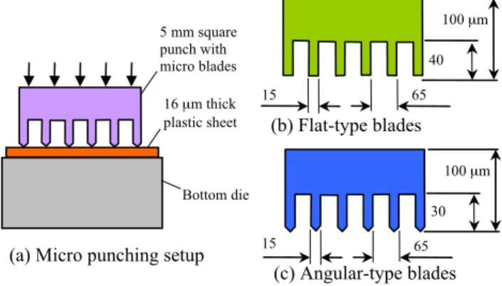
A sketch of a micro punching process is presented in Fig. 1(a), in which the punch with micro blades is directly pressed onto the plastic sheet. The blades may be built in different tip shapes, e.g. flat or angular shapes as shown in Figs. 1(b) and (c). According to silicon etching and LIGA-like techniques [5], possible blade angles including 70o, 90o , 110o and 180o were considered in this study. With a pitch of 65 µm, 76 micro blades were parallel on a 5 mm square punch. The angle of the micro blade could affect the micro punching process but the deformation during the mi-cro punching process is difficult to be observed by experi-mental approaches.By using a simulation technique, e.g. the finite element method, the forming at micro scale could be revealed.
Fig. 1: Sketch of the punching of micro plastic tags
B. NUMERICAL MODELS
This study uses DEFORM 2D to investigate the effect of blade angle on the punching process of micro plastic tags. The punch and the bottom die were treated as rigid materials and the plastic sheet made from PET (Polyethylene Tere-phthalate) was considered as having rigid-plastic behavior. Due to the symmetry and periodic conditions, only one blade was modeled in the simulations with plane strain conditions.
(b) Flat-type blades
(a) Micro punching setup 15 µm 65 µm 30 µm 100 µm Bottom die 5 mm square punch with micro blades 16 µm thick plastic sheet 65 µm 40 µm 100 µm 15 µm (c) Angular-type blades 157
The stress-strain curve of the sheet was determined by the experiments according to ASTM D882 standard. The curve given in Fig. 2 shows the PET sheet has an elastic and linear strain-hardening plastic behavior. To model the friction at the interface between the punch blade and the sheet, the con-stant shear model using a friction factor of 0.359 was em-ployed. The friction factor was obtained in terms of ASTM D1894 standard. The punch speed was set to 0.1 mm/s which was also used in the later experiments. Moreover, a convergence analysis on different number of elements was conducted in order to ensure theusabilityof the predictions. The range of the number of elements for the convergence analysis was between 6000 and 14000. The study concluded that the simulation can be converged for the cases having the elements more than 12000.
Fig. 2: Stress-strain curve of PET sheet
C. PREDICTED RESULTS
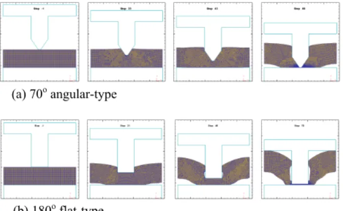
The simulations using various blade angles in the micro punching processes were performed in order to understand the deformation behaviors. The predicted results show that the quality of the sheared profiles of the sheet is affected by the blade angles. Fig. 3 shows that the sheet punched by the 70o angular-type blade is gradually separated as the blade moves downwards. The deformed sheet remains in contact with the surface of the blade and slightly moves away from the bottom die. However, in the case of the 180o flat-type blade, the deformed sheet is not fully in contact with the blade, clearly moves away from the bottom die and curves to the blade.These effects become stronger as the blade angle increases from 70o to 180o as illustrated in Fig. 4.Moreover, the surfaces sheared by the 70o angular-type blade are smoother than those by 180o flat-type blade. The quality of the micro plastic tag could be improved by the decrease of the angle of the blade, which was confirmed by the later experiments.
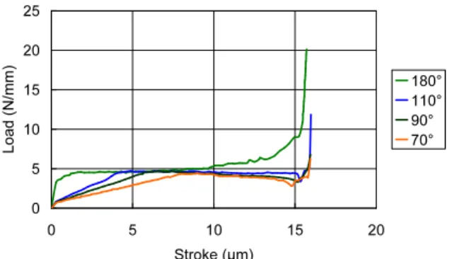
The predicted load curves given in Fig. 5 reveal that the load required by the 180o flat-type rapidly reaches a value close to 5 N/mm, constantly remains to the value, then gradually increases after the stroke of 8 µm and quickly raises to the maximum value. However, a different load curve occurs in the case of the 70o angular-type blade. After the load gradually increases with the stroke and reaches the value of 5 N/mm in the early stage of the punching process, it gradually decreases in the later stage before the rapid
in-crease in the last stage of deformation. The phenomenon becomes more significant as the angle of the blade decreases from 180o to 70o. In the case of the flat-type blade, the mate-rial of the sheet is directly compressed to form lateral flows. As the punch progressively moves, the thickness of the sheet becomes smaller and it will eventually break. In the case of the angular-type blade, the sharp tip causes concentrated stresses on the surface of the plastic sheet and thus leads to the fracture. This can be explained by the observation of the effective stress distributions presented in Fig. 6 that the stresses concentrate at the tip of the blade in the angular-type case but they distribute widely in the flat-type one. As the thickness of the sheet becomes smaller, the resistant to lat-eral flows in the angular-type case gradually reduces. This could be the reason for that the load decreases with stroke after the middle stage of punching in the angular-type case. From the load curves shown in Fig. 5, the dissipated energy to the fracture reduces with the blade angle and the 70o an-gular-type blade consumes the lowest amount of the energy. Moreover, the data given in Table 1 shows that the maxi-mum load of 19.8 N/mm per blade significantly decreases to 6.3 N/mm per blade as the blade angle reduces from 180o to 70o.
The simulations conclude that the punching process using the 70o angular-type blades provides the best quality of the sheared edges and requires the smallest load and the lowest amount of the dissipated energy. The punch with the 70o angular-type blades was fabricated for the experiments and its results were compared with those from the 180o flat-type blades.
Fig. 3: Punching processes using different micro blades
(a) 70o (b) 90o (c) 110o (d) 180o
Fig. 4: Sheared edges resulting from different blade angles
(a) 70o angular-type
Fig. 5: Predicted load-stroke curves
Fig. 6: Effective stress distributions
Table 1: The maximum load predicted by the simulations
Blade angle (degree) 70 90 110 180 Load per blade (N/mm) 6.3 6.8 11.9 19.8
EXPERIMENTS
A. PUNCH BLADE FABRICATION
A negative thick-film KMPR photoresist developed by MicroChem Corporation was chosen to fabricate the micro blades on the punch for experiments. The KMPR can achieve high aspect ratio and is strippable after post expo-sure bake (PEB) and electroforming. Moreover, the KMPR has excellent electrolytic plating bath stability and the di-mension accuracy of the micro structures is improved. After the electroforming process, micro blades were created on the surface of the base which was later cut to form a 5 mm square punch as shown in Fig. 7. Two types of micro blades, the 70o angular-type and 180o flat-type shown in Fig. 8, were developed and used for punching experiments.
(a) Punches after electroforming (b) One single punch
Fig. 7. The punch with micro blades after electroforming
(a) 70o angular-type blades (b) 180o flat-type blades
Fig. 8: Micro blades on the punches
B. EXPERIMENTAL PROCEDURE
This study used a nano-imprinting machine to conduct the micro punching process at room temperature. The punch was compressed by the ram of the machine at a speed of 0.01 mm/s to cut the plastic sheet placedabove the flat surface of the bottom die. It is difficult to obtain the load-stroke curve at the micro scale. However, different values of the applied load result in different ratios of the sheared area that could provide the information on the load requirement for the punch of the micro plastic tag. Therefore, various values of the maximum load were set for the experiments. Moreover, each operation was held at the maximum load for 1 minute to ensure the force was completely applied onto the sheet through the blades. Since the blades were paralleled on the punch surface, it is necessary to perform two punching proc-esses and rotate the PET sheet 90 degree in the second process in order to produce square tags.
RESULTS AND DISCUSSION
A. SURFACE PROFILE
The sliced plastic sheets were investigated by an optical microscope. Figs. 9(a) and (b) show the sheared slices have smooth edges in the cases of the 70o angular-type punch blade. To further investigate their surface profiles by using a confocal microscope, the image presented in Figs. 9(c) and (d) show the height profiles of the slices is more regular and smoother than the one form the flat-type punch blade illus-trated in Fig. 10. The angular-type blade clearly provides a better quality of sliced edges, which lead to a better quality of micro plastic tag as the comparison presented in Fig. 11. B. LOAD COMPARISON
Table 2 shows that the ratio of sheared area increases with the load in both 70o angular-type and 180o flat-type punch-ing processes. The ratio was estimated by uspunch-ing an image analysis approach. The measured load of the angular-type blade is 5.5 kN which is lower than 8 kN needed in the case of the flat-type blade. Moreover, the difference between the predicted and measured loads in the case of the angular-type blade is greater than the one of the flat-type blade. This may be explained by that the height of the angular blades may vary and cause the problem with flatness. In the case of the flat-type blade, the tips of blades are easier to maintain the accuracy through the electroforming process. The predicted load, 7.52 kN, is in good agreement with the measured one, 8.0 kN. Both simulation and experimental results show that a smaller blade angle provides a better edge quality and re-quires a lower load.
(a) 70o angular-type (b) 180o flat-type
C. BLADE STRENGTH AND LIFE
The micro blades on the punch were fabricated by nickel-cobalt (Ni-Co) alloy electroforming. Their strength is much stronger than the one of the plastic sheet. However, the micro blades were directly pressed on to the flat surface of the steel-based bottom die and small variations of their heights in some regions could result in a non-uniform pres-sure distribution and thus cause stress concentrations in the regions. This could reduce the life of the micro blades. In the present study, the developed micro blades can sustain sev-eral punching operations without damages. To prolong the life of micro blades, a better process for producing more uniform distributions of the blade heights and a coating technique, such as diamond-like carbon coating, to improve the surface strength may be applied.
Fig. 9: The slices produced by 70o angular-type blade
Fig. 10: The slices produced by 180o flat-type blade
(a) 70o angular-type (b) 180o flat-type
Fig. 11: Micro plastic tags produced by different types of blade Table 2: The maximum load comparison
70o angular-type blade 180o flat-type blade
Sim. Experiment Sim. Experiment Load (kN) Load (kN) Shearing ratio (%) Load (kN) Load (kN) Shearing ratio (%) 3.5 69 7.0 79 4.0 73 7.5 91 4.5 79 8.0 100 5.0 83 9.0 100 2.39 5.5 100 7.52 10.0 100 SUMMARY
This study uses simulation and experimental approaches to investigate the effects of blade angle on the fabrication of 50 µm square plastic tags. By using silicon etching and LIGA-like processes, 70o angular-type blades and 180o flat-type blades were constructed on the punches for the ex-periments. Simulations show that the load needed in the an-gular-type blade is about a third of the one required in the flat-type blade. The clear decrease in the load has also been observed in the experiments in which 31 percent load reduc-tion is achieved. Both simulareduc-tion and experimental results show that a higher quality of sheared edge and a lower load can be achieved by using the angular-type blades in the punching process of micro plastic tags.
ACKNOWLEDGEMENTS
The authors acknowledge the financial support of the Na-tional Science Council of Taiwan (Grant No: NSC 98-2221-E-151-002) and the MEMS & Precision Machinery R&D Center in the National Kaohsiung University of Ap-plied Sciences for this work.
REFERENCES
[1] B. Shetty, “Fluorescent glitter for use in cosmetic applications,”
Research Disclosure, vol. 505, 2006, pp. 523.
[2] R. Lee, “Micro-technology for anti-counterfeiting,” Microelectronic
Engineering, vol. 53, no. 1-4, 2000, pp. 513-516.
[3] M. Gale, K. Knop, and R. Morf, “Zero-order diffractive microstructures for security applications,” Proceedings of SPIE, vol. 1210, 1990, pp. 83.
[4] D. C. Pang, and C. C. Chang, "Design, fabrication and testing of the micro punch for micro plastic tag," in Proceedings of the International
Conferences on Multi-Material Micro Manufacture (4M)/ International Conferences on Micro Manufacturing (ICOMM) Conference, 2009, pp.
89-92.
[5] M. Madou, Fundamentals of microfabrication: the science of miniaturization, 2nd ed., CRC, 2002, pp. 183-251.
(a) The sheared slices on punch blades
(c) Surface image
(b) The sheared slices re-moved from punch blades (a) The sheared slices on
punch blades
(c) Surface image
(b) The sheared slices re-moved from punch blades
(d) Height profile
國科會補助計畫衍生研發成果推廣資料表
日期 2010年10月27日國科會補助計畫
研發成果名稱
發明人
(創作人)
技術說明
技術移轉可行性及
預期效益
技術/產品應用範圍
產業別
計畫名稱: 計畫主持人: 計畫編號: 學門領域: (中文) (英文)成果歸屬機構
(中文) (英文) 子計畫三:純銅微擠製製程及其應用之研究 張朝誠 98 -2221-E -151 -002 - 應力應變與成型 純銅晶粒細化Grain Refinement of Copper
國立高雄應用科技大學 張朝誠 本技術利用等徑轉角擠製與適當的熱處理程序,對純銅進行晶粒之細化處理。 純銅於室溫下經六道次的等徑轉角擠製,配合適當的退火溫度與持溫時間,分 別以空冷與水冷方式冷卻至室溫。經等徑轉角擠製處理之純銅,其晶粒明顯的 被細化至數微米大小。簡單壓縮試驗與微硬度測試顯示,其破裂點之真實應力 與真實應變量較原始材料之試片高,這表示晶粒細化可提高純銅之延展性。另 外,以微逆向擠製製作圓杯之結果也顯示,晶粒細化可改善純銅成形過程之流 動而獲得均勻杯緣高度與均勻壁厚之成品。此晶粒細化技術可提高純銅成形性 與產品之品質。
This technique uses equal channel angular extrusion (ECAE) processes and heat treatments to refine the grains of copper. After 6 ECAE processes, the copper is heat treated and cooled by air and water to room temperature. By using the technique, the grains in copper after the ECAE processes can be refined to the size of few microns The results from the simple-upsetting and hardness tests show that the amounts of the maximum true stress and the maximum true strain are increased. These indicate the mechanical properties and formability of the processed copper are improved. Moreover, the processes of backward extrusion for fabricating cups show that the grain
refinement can improve material flow and thus lead to better quality of thickness and rim height distribution in extruded copper cups. 金屬業;模具製造業;機械製造業
精微金屬加工
此技術可有提高銅之成形特行與強度,可廣泛用於各種銅成品之製造。
98 年度專題研究計畫研究成果彙整表
計畫主持人:張朝誠 計畫編號: 98-2221-E-151-002-計畫名稱:金屬微成形製程及其應用之研究--子計畫三:純銅微擠製製程及其應用之研究 量化 成果項目 實際已達成 數(被接受 或已發表) 預期總達成 數(含實際已 達成數) 本計畫實 際貢獻百 分比 單位 備 註 ( 質 化 說 明:如 數 個 計 畫 共 同 成 果、成 果 列 為 該 期 刊 之 封 面 故 事 ... 等) 期刊論文 0 0 100% 研究報告/技術報告 0 0 100% 研討會論文 1 2 100% 篇 論文著作 專書 0 0 100% 申請中件數 0 0 100% 專利 已獲得件數 0 0 100% 件 件數 0 0 100% 件 技術移轉 權利金 0 0 100% 千元 碩士生 3 3 100% 博士生 0 0 100% 博士後研究員 0 0 100% 國內 參與計畫人力 (本國籍) 專任助理 0 0 100% 人次 期刊論文 0 2 100% 研究報告/技術報告 0 0 100% 研討會論文 1 1 100% 篇 論文著作 專書 0 0 100% 章/本 申請中件數 0 0 100% 專利 已獲得件數 0 0 100% 件 件數 0 0 100% 件 技術移轉 權利金 0 0 100% 千元 碩士生 0 0 100% 博士生 0 0 100% 博士後研究員 0 0 100% 國外 參與計畫人力 (外國籍) 專任助理 0 0 100% 人次其他成果