ELSEVIER 0263-8223(95)00070-4
Composite Structures 32 (1995) 391-398 0 1995 Elsevier Science Limited Printed in Great Britain. All rights reserved 0263~8223/95/$9.50
Maximum stiffness design of laminated
composite plates via a constrained global
optimization approach
T. Y. Kam & E M. Lai
Department of Mechanical Engineeting, National Chiao Tung University, Hsin-Chu 30050, Taiwan, Republic of China
The optimal lamination arrangements of laminated composite plates with maximum stiffness subject to side constraints are investigated via a constrained multi-start global optimization approach. In the optimal design process, the deformation analysis of laminated composite plates is accomplished by utilizing a shear deformable laminated composite finite element and the optimal design problem, which has been converted into an unconstrained minimization problem via the general augmented Lagrangian method, is solved by utilizing the proposed unconstrained multi-start global optimization technique to determine the optimal fiber angles and layer group thicknesses of the laminated composite plates for attaining maximum stiffness and simultaneously satisfying the imposed side constraints. The feasibility of the proposed constrained multi-start global optimization algorithm is validated by means of a simple but representative example and its applications are demonstrated by means of a number of examples on the maximum stiffness design of symmetrically laminated composite plates. The effects of length-to-thickness ratio, aspect ratio, and number of layer groups upon the optimum fiber angles and layer group thicknesses of the plates are investigated.
INTRODUCTION
In recent years, the increasing use of laminated composite materials in the construction of mechanical, aerospace, marine and automotive structures has made the design of laminated composite structures an important research topic. The common objective in the optimal design of laminated composite structures is to design layer orientations, layer thicknesses or number of layers which will give the minimum weight of the structure and satisfy the imposed constraints. A selected list of some of the lit- erature published in this area is given in the references. lP7 Recently, a number of research- ers have studied the optimal design of laminated composite plates for attaining better behavioral performances.8-12 Although a sub- stantial amount of effort has been devoted to this area, as indicated by the extensive literature published on the subject, a vast proportion of the published work is limited to simple plates
consisting of a very few layers. As is well known, laminated composite plates may be composed of many layers of different orientations and even a relatively simple composite plate may possess many design variables. The increase in the number of design variables when coupled with the highly nonlinear way in which strains and deflections vary with changes in fiber ori- entation can result in great difficulties in obtaining convergence to a local minimum when conventional optimization techniques used by the previous researchers are employed. Furthermore, it appears to be extremely expen- sive if not intractable to find the global optimum using the conventional optimization techniques. For these reasons the aforemen- tioned works on the optimal design of laminated composite plates were restricted to fairly simple cases and the results have there- fore found only limited applications in practical design. It is obvious that if a broader applica- tion of optimal design in laminated composite 391
392 T. I! Kam, R M. Lai
structures is desired, more efficient and reliable global optimization techniques will be required.
Recently, Kam & Snyman13 have proposed an unconstrained global optimization technique for the design of fiber angles of laminated com- posite plates with maximum stiffness. The unconstrained global optimization method has also been successfully used in designing lami- nated composite plates for maximum buckling strength or vibration frequency.‘4-‘5 In this paper, the previously proposed unconstrained global optimization method is extended to treat layer group thicknesses as design variables and include side constraints. In the optimal design process, the finite element analysis of the lami- nated plates is accomplished using a shear
-
N1
N2
QYQX
N6
Ml
M2
M6
-
1 = -All
A12
00
A16
A12
A22 0
0
A26
0 0 A44A45 0
0 0 A45A55 0
A16 A26 0 0 A66
Bll B12 0 0 B16 B12 B22 0 0 B2b B16 B26 0 0 Be6 -
B11
B 12 0 0 B D: 012 016B1;
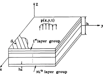
B2> 0 0 B D: D2: D2,as shown in Fig. 1. The plate is composed of a finite number of layer groups in which each layer group contains several orthotropic layers of same fiber angle and uniform thickness. The x and y coordinates of the plate are taken in the midplane of the plate. The displacement field is assumed to be of the form
where u 1, u 2, u3 are displacements in the X, y , z directions, respectively, and uo, vo, w the asso- ciated midplane displacements; $I and I,+~ are shear rotations.
The plate constitutive equations are written
u
0,x VO,YW.Y+$Y
I
w,, + $x
1
uo,y+vo,x
F-
L:I
+
$y,x
(2)
deformable finite element and the original con- strained optimization problem is converted into an unconstrained one via the general augmen- ted Lagrangian approach.16 The converted unconstrained optimization problem is then solved using the previous unconstrained global optimization algorithm to determine the opti- mal layups of the laminated composite plates. The feasibility of the present optimization algo- rithm is first validated by means of a simple but representative example. A number of examples on the maximum stiffness design of symmet- rically laminated composite plates subject to thickness constraints are given to illustrate the applications of the proposed method and study the effects of length-to-thickness ratio, aspect ratio, and number of layer groups upon the optimal solution of the plates.
FINITE ELEMENT ANALYSIS OF LAMINATED COMPOSITE PLATES
Consider a rectangular plate of area a x b and uniform thickness h subject to transverse load
where N1, N2,. . . , ibfb are stress resultants; material components A,, B, and D, are given bY s h/2 (4@,&)= _-h,2
Q$ym)(b,z2)dz
(i,j=1,2,6) and s h/2 A,=k;k,& A,= _h,2Q$+ dz
(34
(i,j=4,5; a=6-i, p=6-j) (3b)where Q, are material constants; the super- script m denotes layer number, and ki are shear correction factors which can be evaluated from the exact expressions given by Whitney.17 The derivation of the governing equations for the plate is based on the virtual work equation. The introduction of virtual displacements 6ui to the plate under static equilibrium gives the virtual work equation asl8
Maximum stifsness design of laminated composite plates 393
h
3-
9 /X
Fig. 1. Laminated composite plate.
where I/ is the volume and pi surface tractions acting over the area S1 of the plate. Herein, the finite element method developed by Kam & Chang” is adopted in the derivation of the load-displacement equations for the plate. The element has eight nodes and the quadratic for- mulation of the serendipity family with reduced integration of the 2 x 2 Gauss rule has been used for constructing the element stiffness matrix.
KA=P (5)
where K, A, P are the structural stiffness matrix, displacement vector and load vector, respec- tively.
When the nodal displacements of the plate have been solved from eqn (5), the strain energy U stored in the plate is computed as
U=+ A’KA. (6)
The rates of change of strain energy with respect to design variables Xi are
au
1ax,=-7 At
(7)
MAXIMUM STIFFNESS DESIGN
The objective of the present optimal design of a laminated composite plate with given plate thickness and number of layer groups NL sub- jected to thickness constraints is the selection of fiber angles and thicknesses of the layer groups which gives the maximum stiffness of the plate. It is noted that the minimization of plate strain energy is equivalent to the maximization of
plate stiffness.8 In mathematical form, the opti- mal design problem is stated as
minimize U= U(h, 0) subject to 0” I Oi I 180” hi>0 i=l,...,NL (8) r NL 1 1 H=x h,-h=O 1 L i=l -I where h=(hl,h2 ,..., hNL)f, 8=(81,8z ,...) 6,)’
are the vectors of layer group thicknesses and fiber angles, respectively.
The solution of the above constrained optimi- zation problem using the conventional optimization techniques16 can only yield a local minimum, not to mention the difficulty that may be encountered in enforcing convergence of the solution. Herein, a constrained multi-start global optimization method is presented for solving the above optimal design problem for attaining the global optimum solution. The above problem of eqn (8) is first converted into an unconstrained optimization problem by cre- ating the following general augmented Lagrangian16 ‘P(Q,hJ,rP)=U(O,h)+~ [A;xj+rPxf] j=l +[A NL+1H+@f2] with (9) gj(hj)=-hi<0 j=l,...,NL (10) where 5, rP are multipliers.
The update formulae for the multipliers J.j and rP are
A~i”“=A~+2r+~ j=l,...,NL+l
(11)
where the superscript n denotes iteration num- ber; y is a constant; rp”” is the maximum value of rP. The initial values of the multipliers and the values of the parameters (y,r,““) are chosen asAq=l*O j=l,...,NL+l
r”,=0*4 y= 1.25
394 7: Y Kam, E M. Lai
r$-= 100
The maximum stiffness design of the laminated composite plate has thus become the solution of the following unconstrained optimization prob- lem
Minimize !P(8,h,&r,)
with respect to 8 and h
subject to O”rQi<180” i=l,...,NL (13) The above unconstrained optimization prob- lem can be solved straightforwardly by using the previously proposed unconstrained multi-start global optimization algorithm.‘3V20 The basic idea of the unconstrained multi-start global optimization method is to solve the problem of unconstrained minimization of a differentiable objective function F(y), y?YCR” and FCC’, with several local minima Fj and corresponding local minimizers fjm It is noted that, for
example, in the optimal design of laminated composite plates, y and F(y) become [Q,h] and Y (0, h), respectively. In the global minimization process, a series of starting points are selected at random from the region of interest and a local minimization algorithm is used from each starting point. The search trajectories used by the local minimization algorithm are derived from the equation of motion of a particle of unit mass in an n-dimensional conservative force field, where the potential energy of the particle is represented by F(y(t)). In such a field the total energy of the particle, consisting of its potential kinetic energies, is conserved. The motion of the particle is simulated and by monitoring its kinetic energy an interfering strategy is adopted which ensures that potential energy is systematically reduced. In this way the particle is forced to follow a trajectory towards a local minimum in potential energy, f. It is noted that if the trajectory leaves the domain of interest at the point Qp where one or more of the components Q,, take on values such that either oppi> n or epi<O, then the constraints are imposed by continuing the trajectory at the point 0$ with components identical to 0, except for the components corresponding to the vio- lated constraints. These components are replaced as follows
t3j,i=Opi-m7c if Op,i>7t and
Q~i=Opj+m7c if 8pi<O; m=1,2,3,... (14)
Here the value of m is chosen in such a way that 6& satisfies the constraints. By uninterrupt- ing the motion of the particle with conserved total energy, other lower local minima, includ- ing in particular the global minimum, are obtained and recorded when the particle is trav- eling along its path. The motion of the particle is stopped once a termination criterion is sat- isfied. The same procedure is applied to the other starting point. As the process of searching for the global minimum continues, a Bayesian argument is used to establish the probability of the current overall minimum value of F being the global minimum, given the number of starts and number of times this value has been ach- ieved. The multi-start procedure is terminated once a target probability, typically 0.998, has been exceeded. The main advantage of this multi-start global optimization algorithm is that it can determine the global optimal solution in a very efficient and effective way.
NUMERICAL EXAMPLES
The aforementioned constrained global optimi- zation technique will be applied to the design of symmetrically laminated composite plates with simply supported or fixed edges subjected to the center point load P. The boundary conditions for the two types of support are shown in Fig. 2. The material properties used in the following design are given as
El
-= 181.0, E2 Eo -= 10.3, -=7*17 G12 Eo Eo G23-=3*O, ~,~=0*25, G12=G13, Eo=l*O GPa
Eo
The advantage of using the present method in designing laminated composite plates is first illustrated by means of an example on the design of simply supported symmetric four-lay- ered and centrally loaded plates with various aspect ratios. The results obtained by the pres- ent approach are listed in Table 1 in comparison with those obtained by using other method. The minimization routine BCONF of the IMSL mathematical package2’ has been used to solve the above optimal design prob- lems for determining the fiber angles and
Maximum stiffness design of laminated composite plates 395 b vo - -0 w=o I$=0 , b uo =o w=o !ko uo =o vg =o w=o &=o -$=O a X I UrJ =o vo =o w=o 7ox=o I$=0 uo =o v. =o w=o 34=0 Y Y I$=0
(a) simple support (b) Fixed support Fig. 2. Boundary conditions of laminated plates.
Table 1. Optimal solutions obtained via different design methods for a simply supported symmetric four-layered and centrally-loaded plate (u/h= 10, WC=WC[E,bh3/( pu3)] x ld)
Design method
(i) Present method (ii) Previous method13 (iii) BCONF”
Fiber Normalized @‘;. Fiber Normalized I&“ Difference Fiber Aspect angles layer group
Normalized @c angles
r;;: (degrees) thickness
layer group
(degrees) thickness (ii)-(i)
angles layer group thickness
(hi=hJh) (hi=hJh) __ (ij % (degrees) (hi=hJh)
0,5 [58*9”/ [0.09575/ 0.84 - 59.7”],? [72W/ [0.25/ 0.89 5.95 0.404251, - 56.0”],s [59.5”1 0.86 0.25],T [0.1107/ -56.2”],s 0.3893], 1.0 [45”/ [0.09660/ 2.76 [45”/ [0.25/ 3.21 1630 - 45”lS 0.40340], - 46.0”], [45”/ 0.25], [0.1121/ 2.78 - 46.0”],s 0.38791, 1.2 [41.2”/ IO.096491 3.64 [40.0”/ [0.25/ 4.23 16.21 3.69 -41.5”],s o.40351],Y -41.0”], [40.9? 0.251, [0.1126/ -41.0”], 0.38741,
thicknesses of layer groups. The BCONF rou- tine can minimize a function of y1 variables subject to side constraints using a quasi-Newton method and finite-difference gradient. In solv- ing the optimal design problems, the present method has used ten starting points to find the global optimal solution with probability O-998 while the BCONF routine has used 28 starting points in obtaining the results listed in Table 1. Furthermore, the present method has no con- vergence problem while the successful use of BCONF routine greatly depends on the choice of the starting point. For the BCONF routine, divergence of solution may occur if the starting point is close to the bounds of the constraints. Therefore, this proves that the present approach is comparatively efficient and can yield plates with greater stiffness. The present
method is then used to study the optimal design parameters of simply supported or clamped laminated composite plates. The optimal layer group parameters (fiber angles and normalized thicknesses) of the simply supported plates with various aspect ratios (b/a=O-5, 1.0, l-2), num- bers of layer groups (NL =4, 6, 8) and length-to-thickness ratios (a/h=5, 100) are tabu- lated in Tables 2 and 3 while those for the plates with fixed edges are in Tables 4 and 5. It is noted that as shown in Tables 2 and 3 for the simply supported plates the plate thickness is controlled by one layer group whose fiber angle normally falls in the range from approximately
- 61” to -40”. For example, the layer group of fiber angle -56.0” contributes 82% of plate thickness for the four-layered plate with
396 7: E: Kam, E M. Lai
Table 2. Optimal solutions of simply supported symmetrically laminated composite plates subjected to center point load (a/h=5, W,=W,{E,W/(pa3)] x 103) Aspect ratio (b/u) 0.5 1.0 1.2 Optimal solution Fiber angle Layer group thickness
hi/h Deflection WC
Fiber angle Layer group thickness
hi/h
Deflection WC Fiber angle Layer group thickness
hi/h Deflection WC 4 [54.3”/ - 56.0”], [O-08806/0.4 11 94],v 2.9758 [45”/ - 45*0”], [0.09143/0.40857], 6.35447 [41.6”/-42.0”], [0.09156/O-40844], 7.9575
Number of layer groups (AK)
6 8 [86.1”/3.3”/-54W’], [86~1”/3~3”/68~8”/ - 543”], [0~01540/0~07210/0~41250], [0.00556/@01598/ 0.06748/0.41098], 2.5426 2.5424 [79.6”/38+9’=/ - 44.1°],T [81~3°/27~80/45~30/-44.11, [0.01465/0.07977/O-405581. [0~01309/0~02601/ 0.05833/0.40257], 6.3159 6.2953 [ -41-T/-42.9”/-41.9”], [84~5“/28~9”/40~40”/-41.9”], [0~09211/000007/0-407821, [O-O1 184/0.03601/ 0.05052/0.40146],T 7.9440 7.8605
Table 3. Optimal solutions of simply supported symrpetrically laminated corn
load (u/h=lOO, WC=WC[E,bh3/(pa3)] x 1 ) $” site plates subjected to center point
Aspect ratio (b/u)
Optimal solution
4
Number of layer groups (NL)
6 8 0.5 Fiber angle
Layer group thickness hi/h Deflection PC 1.0 Fiber angle
Layer group thickness hJh Deflection WC 1.2 Fiber angle
Layer group thickness hi/h Deflection WC [59W - 60.3qS [60.0”/- 60.2”/66.1”], [0.10249/0.39751], [0~10204/0~39776/0~00020]. 0.2710 [45”.0/- 45$qS [0.10368/0.39632],T 0.2709 [ - 45~0°/45~00/ - 45*0”], [0~00050/0~10397/0~39553], 1.4954 [41.0”/-4OY], [0.10392/0.39608],T 1.4954 [41W-40*9°/-40~90], [0~04850/0~05530/0~39620], 2.0973 20971 [ - 57~O”/60~Oo/65~70/ - 60.4”], [0+IO060/0~10280/ 0WO40/0~39620],~ 0.2709 [ - 45.2”/-45.2”/ - 45.2”/45.0”], [0~01309/0~02601/ 0.05833/0.40257], 1.4952 [ -41w41v-37~6”/-41*4”], [0~00003/0~10388/ 0~00001/0~39608], 2.0971
hand, aspect ratio b/u has some effects on the optimal fiber angles of the simply supported plates. For instance, the optimal fiber angles change from [54*3/- 56.01s for b/a =O-5 to [41+6/-42.01s for b/a = 1.2 as shown in Table 2. As for the clamped plates, the results in Tables 4 and 5 show that for thin plates (a/h= 100) the optimal fiber angles tend to be a combination of 0” and 90”. However, for some thick plates (al
h =5) or for thin plates with b/a = 1 and NL =6
and 8, the optimal fiber angles may deviate from 0” or 90”. For example, it is interesting to point out that for the clamped plate with bl
a= 1.0, the optimal fiber angles change from
[0/9O]s for u/h= 100 to [45/-451s for u/h=5 as shown in Table 4. On the other hand, aspect ratio b/u may have some effects on the optimal fiber angles of the clamped plates. For instance,
for a/h=5 the optimal fiber angles change from [50*4/-52.61s for b/u=O-5 to [40.7/--38*l]s for
b/u= 1.2 as shown in Table 4. similar to the
simply supported plates, plate thickness is gen- erally controlled by one layer group. For example, the layer group of 90” possesses 93% of the thickness of the four-layered plate with al
h= 100 and b/u=O-5 in Table 5. It is also worth
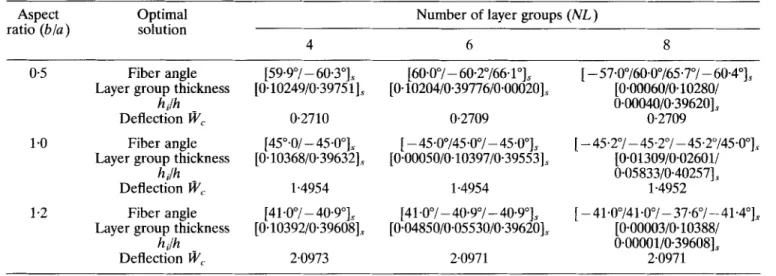
noting that the number of layer groups has insignificant effects on the total plate thickness for both the simply supported and clamped lam- inated composite plates which have been optimally designed. In general, the use of only six layer groups can yield the approximately global maximum stiffness for the plates. Hence, in view of the fact that the use of fewer number of layer groups in design can greatly reduce the time for manufacturing composite laminates,
Maximum stifsness design of laminated composite plates 397
Table 4. Optimal solutions of clamped symmet@cally laminated composite plates subjected to center point load (u/h=5, W,=W,[E,W/@a3)] x Id) Aspect ratio (b/a) 0.5 1.0 1.2 Optimal solution Fiber angle Layer group thickness
hi/h Deflection WC
Fiber angle Layer group thickness
hi/h Deflection WC
Fiber angle Layer group thickness
hi/h Deflection WC 4 [50+‘/ - 52.6”]S [0.08676/0.41324], 2.5162 [45W - 45.0”], [0~08596/0~41404], 5.8337 [40.7”/ - 38.1”], [0~08486/0~41514], 7.1491
Number of layer groups (AX)
6 8 [ -4~1°/-71~30/52~5”], [5.4”/74.5’/ - 46.5”/- 55.4”], [0~01865/0~06280/0~41855], [0.021490/0.05745 0~00002/0~42104],~ 2.4438 2.4327 [84.1”/22.2”/-44.4”], [86.2“/7.6”/479’ - 42.9”], [0~02265/0~06050/0~41585], [0~01309/0~02601/ 0.05833/0.40257], 5.6573 5-6154 [96.3”/ - 20.4”/38+3”], [94.4”/-7.85”/-44.3°/37.1”],T [0~02255/0~06593/0~41152], [0~02089/0~04075/ 0.03364/0.40472],T 6.9241 6.8802
Table 5. Optimal solutions of clamped symmetr&ally laminated composite plates subjected to center point load (u/h=lOO, W,=W,[E,bh3/(pu3)] x ld) Aspect ratio (u/b) 0.5 1.0 1.2 Optimal solution Fiber angle Layer group thickness
hi/h Deflection WC.
Fiber angle Layer group thickness
hi/h Deflection WC
Fiber angle Layer group thickness
hi/h Deflection WC 4 [00/900], [0.03519/0.46481], 0.1170 [00/900], [0.08521/0.41479],T 0.7747 [OY90°], [0.08521/0.41479j. 0.9771
Number of layer groups (NL)
6 8 [90°/oo/90q, [0”/90”/0”/90”], [0~00450/0~03590/0~45960], [0.03515/0+04072/ 0~00001/0~42412], 0.1170 0.1168 [4.9”/85.7”/ -- 7.3”lS [3~O”/81~30/8~O”/-79~lo].~ [0~02650/0~01043/0~45960], [0.03998/0.03607/ 0.05806/0.36589], 0.7724 0.7720 [o”/900/o”], [0°/900/900/oo], IO*001 70/0.045 lo/O.438201 c 10.00172/0,04055/ I” L 2.. iIO5050/0.43721], 0.9764 0.9758
the optimal number of layer groups obtained herein demonstrates one of the merits of the present design method.
CONCLUSION
Optimal lamination arrangements of laminated composite plates designed for maximum stiff- ness subject to side constraints were investigated via a constrained multi-start global minimization approach. Results for symmetri- cally laminated multi-layer plates of various aspect ratios, different numbers of layer groups and boundary conditions subject to center point load were obtained. The effects of aspect ratio, length-to-thickness ratio and number of layer
groups on the optimal lamination arrangements were studied. It has been shown that the pres- ent constrained optimization technique can yield the global optimal design of laminated composite plates without considering many design variables. The constrained multi-start global minimization algorithm is of promise for further applications to the optimal design of more complex laminated composite structures.
ACKNOWLEDGEMENT
This research was supported by the National Science Council of the Republic of China under Grant No. NSC 83-0401-E009-103. Their support is gratefully appreciated.
398 7: Y Kant, E M. Lai
REFERENCES 8 (1985) 253-63.
11. Chen, T. L. C. & Bert, C. W., Design of composite material plates for maximum uniaxial compressive buckling. Proc. Oklahoma Acad. Sci., 56 (1976) 104-7. Muc, A., Optimal fiber orientation for simply sup- ported, angle-ply plates under biaxial compressions.
Comput. & Struct., 9 (1988) 161-72.
Kam, T. Y. & Snyman, J., Optimal design of lami- nated composite structures using a global optimization technique. J. Comp. Struct., 19 (1991) 351-70. 1. 2. 3. 4. 5. 6. 7. 8. 9. 10.
Khot, N. S., Computer program (OPTCOMP) for optimization of composite structures for minimum weight design. AFFDL TR-76-149, Wright-Patterson Air Force Base, Dayton, OH, 1977.
Massard, T. N., Computer sizing of composite lam- inates for strength. J. Reinf Plastic Comp., 3 (1984)
300-45.
Schmit, L. A. & Farshi, B., Optimum design of lami- nated composite plates. ht. I. Numer Meth. Engng, 11 (1977) 623-40.
Stroud, W. J. & Agranoff, N., Minimum-mass design of filamentary composite panels under combined loads: design procedure based on simplified buckling equations. NASA TN D-8257, NASA Langley Research Center, Hampton, VA, 1976.
Hirano, Y., Optimum design of laminated plates under shear. J. Comp. Mat., 13 (1979) 329-34.
Hirano, Y., Optimum design of laminated plates under axial compression. AIAA J., 17 (1979) 329-34. Kam, T. Y. & Lai, M. D., Multilevel optimal design of laminated composite plate structures. Comput. &
Struct., 31 (1989) 197-202.
Tauchert, T. R. & Adibhatla, S., Design of laminated plates for maximum stiffness. J. Comp. Mat., 18 (1984) 58-69.
Adali, S. & Duffy, K. J., Design of antisymmetric hybrid laminates for maximum buckling load: I. Opti- mal fiber orientation. Comp. Struct., 14 (1990) 49-60. Tauckert, T. R. & Adibhatla, S., Design of laminated plates for maximum bending strength. Engng Optim.,
12. 13. 14. 15. 16. 17. 18. 19. 20.
Kam, T. Y. & Chang, R. R., Design of laminated composite plates for maximum axial buckling load and vibration frequency. J. Computer Methods in Appl.
Mech. & Engng, 106 (1993) 65-81.
Chang, R. R., Chu, G. H. & Kam, T. Y., Design of laminated composite plates for maximum shear buck- ling load. J. Energy Resources Tech., ASME, 115 (1993) 314-22.
Vanderplaats, G. N., Numerical Optimization Tech-
niques for Engineering Design: With Applications.
McGraw-Hill, Inc., New York, 1984.
Whitney, J. M., Shear correction factors for ortho- tropic laminates under static load. J. Appl. Mech., 40
(1973) 302-4.
Washizu, K., Kwiational Methods in Elasticity and
Plasticity. Pergamon Press, New York, 1988.
Kam, T. Y. & Chang, R. R., Finite element analysis of shear deformable laminated composite plates. J.
Energy Resources & Tech., ASME, 115 (1993) 41-6. IMSL User’s Manual, IMSL Incorporation Houston, Texas, 1989.
![Table 1. Optimal solutions obtained via different design methods for a simply supported symmetric four-layered and centrally-loaded plate (u/h= 10, WC=WC[E,bh3/( pu3)] x ld)](https://thumb-ap.123doks.com/thumbv2/9libinfo/7671103.141367/5.922.213.704.126.432/optimal-solutions-obtained-different-supported-symmetric-layered-centrally.webp)
![Table 5. Optimal solutions of clamped symmetr&ally laminated composite plates subjected to center point load (u/h=lOO, W,=W,[E,bh3/(pu3)] x ld) Aspect ratio (u/b) 0.5 1.0 1.2 Optimal solution Fiber angle Layer group thickn](https://thumb-ap.123doks.com/thumbv2/9libinfo/7671103.141367/7.919.89.837.510.785/optimal-solutions-clamped-laminated-composite-subjected-optimal-solution.webp)
