Retargetable Exploration Methodology for Heterogeneous Multi-Core SOC
6
0
0
全文
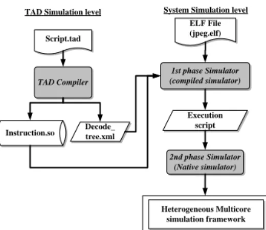
(2) of the system. With the software content in embedded systems is growing. How to make the software development sooner is always an issue. A reliability multi-core simulation framework means the software develop can ahead of the schedule; and the verification with the RTL will be favorably.. 2. Related work Today’s instruction-set simulation techniques include the most flexible but slowest interpretive simulation and faster compiled simulation. Recent research addresses retargetability of instruction set simulators using a machine description language. Embra project [1] provides the highest flexibility with maximum performance but is not retargetable: it is restricted to the simulation of the MIPS R3000/R4000 architecture. A fast and retargetable simulation technique is presented in [2]. It improves typical static compiled simulation by aggressive utilization of the host machine resources. Such utilization is achieved by defining a low level code generation interface specialized for ISA simulation, rather than the traditional approaches that use C as a code generation interface. But the aggressive utilization of the host machine resources is time consuming. As more applications are implemented in software that in turn is growing larger and more complex, a global analysis of such heterogeneous system is a big challenge. A highlevel, layered software-on-hardware performance modelings for multi-threaded multiprocessor systems is presented [4] . However, there is a lack of complete methodologies and tools that cover all the connecting to the modelings of heterogeneous systems in a satisfactory manner. Several approaches have been devised that tend to provide the designers with suitable modelings tools. Another approach is the Trace-driven simulation [7] [8], which stores memory traces from the cycle accurate simulator without considering any resources dependency. It’s extremely fast to the memory tracing for the communication architectures. However the memory traces need huge external storages, so most of the memory traces data have to access from the external storages. Obviously the performance of this method is strongly influence by the I/O. Furthermore, this is static analysis the simulation data, and the simulation needs to dynamic analysis will not consider to use this method. Retargetable compiled simulators based on an architecture description languages have been developed within the Sim-nML (FSim) [9], ISDL (XSSIM) [10] and MIMOLA [11] projects. In summary, none of the above approaches combines retargetability, flexibility, and heterogeneous multi-core automatically simulation performance at the same time.. 3. System Overview Figure 1 is the system flow of this paper. We integrate the TAD compiler, the compiled simulation, and the binary translated workflow with this framework. Figure 2 is the system architecture diagram, users describe the target architecture with TAD script, through the TAD compiler to generate the target architecture simulator (so-called “raw simulator”), and in this stage the users can debug the simulator and the TAD script, until the simulator is robust. Then the users can profile the target applications which will be simulated on the heterogeneous multi-core environment, and insert the instrument in the target application, finally, through the speedup methodologies to speedup the simulator then put them into the multi-core simulation framework. TAD Simulation level. ELF File (jpeg.elf). Script.tad. TAD Compiler. Instruction.so. System Simulation level. Decode_ tree.xml. 1st phase Simulator (compiled simulator). Execution script. 2nd phase Simulator (Native simulator). Heterogeneous Multicore simulation framework. Figure 1: system architecture diagram. Figure 2: Heterogeneous Multi-core Simulation Framework. 2 - 28.
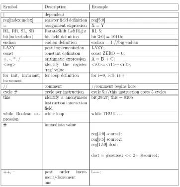
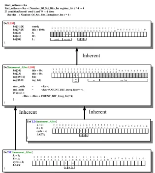
(3) 3.1. Target Architecture Description Language. 3.1.1. We proposed a target architecture description language(TAD) to make the architecture design automatically. TAD’s syntax is easy to understand. It’s designed for describe the instruction sets, register set, pipeline structural and memory architecture, so there is no complicated syntax and it supports single inheritance and bit operations, and users indicate cycle counts of the instruction. In order not to burden the users with too complicated syntax, TAD supports a special instruction ”LAZY”, so that users can use C code to write operations about the instruction themselves, and link with the simulator which is generated by the TAD compiler. TAD has a characteristic of single hierarchical, so it’s an advantage to instructing the reusable sets. The same kind of instruction has the same definition of instructing columns and developing instruction sets mostly go from the wide to the narrow and have a number of overlaps of defining methods. Therefore, without focusing on C/C++ details, using TAD helps the developer take advantage of the codes out of TAD to possess the characteristics of complete interface, bug free, architecture, easy to maintain. Moreover, with TAD, we can have the current waterfall design flow become iteration design flow, and when the developer set up the instruction sets, they can take advantage TAD to describe instructions. As long as deciding the instruction’s prototype, simulators are coming out very soon to progress evaluating. When it needs trade off, the developer just go back to modify TAD a bit, and then simulators can keep going on evaluating.. The TAD compiler also support some validations to the TAD scripts. Including instruction coding space validation, instruction behavior validation, architecture validation. In traditional instruction set design, the designer have to counting the coding space by hand. It’s boring and ease to make mistakes. The TAD compiler will report the conflict coding space and indicate the rest space which can use to insert additional new instructions. The instruction validation verify some instruction execution properties under the pipeline architecture, such as to verify the instructions need how many cycles to finish the execution under the finite state machine. This validation also can estimate the static execution cycles and find out the data hazard between the instructions. In order to make the validation successful, user have to define a constrain file, such like a configure file for the architecture.. Figure 3: Syntax of the TAD Language. 3.1.2. TAD validation. A TAD Example. The benefits of the TAD language are the flexibility and inerrability. Figure 4 is an example to illustrate the ARM “load and store multiple increment after” instructions. The processor’s instructions always have the class property. We can classify the instructions into several classes, such as data processing instruction class, load/store instruction class, branch instruction class and misc class. First, we describe the father class “Load / store multiple”, this class include all of the properties of the Load/Store Multiple type instructions. In this case is the instruction fields’ definition. And then, we describe the child class of the “Load/Store Multiple” class which named ‘Increment after’. This class means the pointer of the stack will increment automatically after each load/store operation. The single inherent is a characteristic of the TAD. It is quite straightforward. In order to make the TAD syntax simple but lost the expression power. Finally, the load instruction with the “Load/Store multiple” and “increment after” properties was defended just inherent the “increment after” class which has the ‘Load/store multiple’ properties. The other characteristic of the TAD command is the “LAZY” keyword. “LAZY” means that the user can describe the instruction behaviors in C language and link it later. This command has 2 benefits. First, the TAD syntax can keep in simple. One of the design goal of the TAD is simple. In slightly speaking, it can not be more complicated than the C language. Sometimes use the C language may have more expression power than the TAD language. And the C language is a well-known and popular language. So, it is good for TAD language to compatible with the C language. Second, the user can reuse their prior behavior model written in C language which just only need to do is wrapped the C model into the interfaces generate from the TAD compiler. The namespace of the fields name definition of the TAD syntax is also an issue. TAD has the “this” command which identified the field name in anonymous. For example,. 3 - 29.
(4) the definition in above example of the “Load/Store Multiple” instruction is “bit[27:25] this = 100b;” which means that the field 25 to 27 are bit fields the default value is 100 and the variable name in C language is LSM 27 25. The inherent. def register{ [r0 ,r1 ,r2 ,r3 ,r4 ,r5 ,r6 ,r7 ,r8 ,r9 , r10,r11,r12,r13,r14,r15,r16,r17,r18,r19, r20,r21,r22,r23,r24,r25,r26,r27,r28,r29, r30,r31,r32];. Start_address = Rn End_address = Rn + ( Number_Of_Set_Bits_In( register_list ) * 4 ) - 4 If conditionPassed( cond ) and W ==1 then Rn =Rn + ( Number_Of_Set_Bits_In(register_list ) * 4 ) Def LSM{ bit[31:28] bit[27:25] bit[22] bit[21] bit[20] }. comd; this = 100b; S; W; L;. 3 3 2 2 2 2 2 2 2 2 2 2 1 1 1 1 1 1 1 1 1 1 9 8 7 6 5 4 3 2 1 0 1 0 9 8 7 6 5 4 3 2 1 0 9 8 7 6 5 4 3 2 1 0 1 0 0 comd. S W L. opcode. TAD support alias, user can use the alias in the TAD script to gain the script's readability.. alias r29 = sp; alias r30 = fp; alias r32 = CPSR;. ARM Load and Store Multiple – Increment After instruction. Define the register set, identified all of the registers in the architecture. alias [r1,r2,r3,r4,r5,r6,r7,r8]=intReg;. TAD can alias a set of the registers. alias r32[31] = N; alias r32[30] = Z; alias r32[29] = C; alias r32[28] = V; r0 = 0; // assign the register default value. Even can name the single bit-field in the register with alias. The naming method in the TAD script is registeralias_field-alias. } Def Increment_After:LSM{ bit[24] this = 0b; bit[23] this = 0b; reg[19:16] Rn; reg[15:0] reg_list;. 3 3 2 2 2 2 2 2 2 2 2 2 1 1 1 1 1 1 1 1 1 1 9 8 7 6 5 4 3 2 1 0 1 0 9 8 7 6 5 4 3 2 1 0 9 8 7 6 5 4 3 2 1 0 0 0 op code. rn. Figure 5: TAD Script Example, the Register Set Definition. reg_list. start_addr = <Rn>; end_addr = <Rn>+COUNT_BIT_1(reg_list)*4-4; if(W==1){ <Rn> = <Rn> + COUNT_BIT_1(reg_list)*4; } }. def [1024]Memory_name[32]; (depth) Def LD:Increment_After{ 3 3 2 2 2 2 2 2 2 2 2 L = 1; 1 0 9 8 7 6 5 4 3 2 1 S = 0; 0 cycle = 4; LAZY; S W }. Def ST:Increment_After{ L = 0; 3 3 2 2 2 2 2 2 2 2 2 S = 1; 1 0 9 8 7 6 5 4 3 2 1 cycle = 2; 1 LAZY; S W }. 2 0. 1 9. 1 8. 1 7. (width). 2 1 1 1 1 1 1 1 1 1 1 9 8 7 6 5 4 3 2 1 0 0 9 8 7 6 5 4 3 2 1 0 1. Figure 6: TAD Script Example, the Memory Definition. L. 1 6. 1 5. 1 4. 1 3. 1 2. 1 1. 1 0. 9. 8. 7. 6. 5. 4. 3. 2. 1. 0. 0 L. Figure 4: TAD Script Example, a ARM’s Load/Store Multiple Increment After. and post implement (LAZY) are two main characteristics of TAD. The first one makes the TAD’s expression clear and the second one makes the TAD more flexible. Figure 5 is an example of the TAD to describe the register configuration in the architecture. User needs to define the register set first, and then he can name the register with specific alias. In order to support the CISC (Complex Instruction Set ) instructions in the future, TAD support the variable length instruction. User do not need to define the instruction’s bit length in the define register block. Figure 6 shows the memory definition in the TAD script. After the keyword “def”, the first argument is the memory depth, the second argument is the memory name, and finally the last argument is the width of the memory. The depth and the width are byte addressable. User can identify the different memory components as he want, some embedded memory system have the split “instruction memory” and “data memory” and the TAD script can handle this well.. 3.2. Simulation speedup As the embedded system is getting more complex and the growing of the embedded software. Each stage of the SoC design will take more time than before. The System level. design is sitting on the root position of the top down design flow. In this stage, the system designer needs to know the estimated information, such as functional accurate, bus communication, event the cycle or power information. System designer needs lots of combinations of the system components, putting them together and analyzing the simulation result. This is time consuming and challenge. It is a big issue to make the simulator faster. In the next section, during the multi-core simulation, the concurrent execution and the event-driven kernel will drop the simulation performance. It is worth to speed up the simulators to make the multi-core simulation faster. In addition, the TAD simulator generation progress makes the simulator robust and easy generated. This can short the time to build up a simulator. There are two kinds of simulation speedup methodologies. One is the compiled simulation which performs compile time decoding of application program to improve the simulation performance. The other is the binary translation which translates the application’s binary code into the host machine code. This is inflexible and unretargetable, but this method can produce the fastest simulator. 3.2.1. 1st phase speedup. Compiled simulator moves the target instruction decode stage to the preprocessing stage. Typical C simulator is “Fetch-Decode-Execution” model which wastes time on the decode stage. The decode component in the simulator is a huge combinations of “if-then-else” or “switch-case” blocks. The procedure of the instruction decode need to go through. 4 - 30.
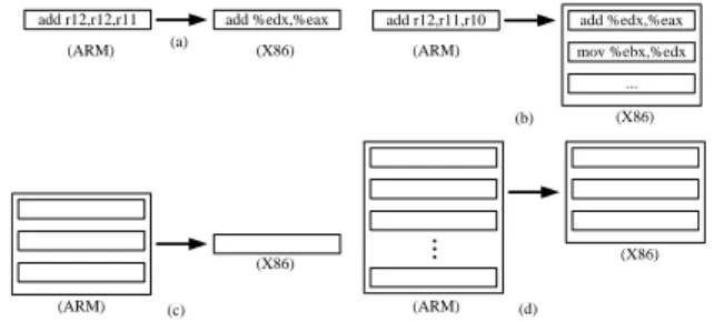
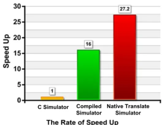
(5) many if-then-else conditions. If the instruction’s “signature” is in the deepest if-then-else blocks, and a huge amount iterations are occurred. This is definitely time-consuming. Because the same instructions appear in each iteration, and the simulator just decode it mechanic. In addition, after decode stage, to correspond behavior function should be invoke, but the function call need to add the prolog/epilog code in front/tail of the function. We move the instruction decode stage to the static time, before we really execute the simulation. The benefit of the compiled simulation is obviously, the 10,000 iterations looping program needs to decode extremely 9,999 times for each instruction in the loop in the “Fetch-Decode-Execution” model. This is exclusive the time to invoke the corresponding instruction behavior function in the execution stage. 3.2.2. 2nd phase speedup. Just In Time (JIT) technique is a well-known for dynamic translation skill. The Simulator interprets the target instructions and translates it into the host machine code and store the mapping relation into a cache table during the run time, as the same target instruction is met, and the host machined code will execute directly. JIT methodology has to compile/interpret the target instruction in the runtime, and this is an overhead to the dynamic translate simulator. If the target application is long term execution, JIT is an efficiency method. Basically, there are four kinds of binary code translations. Figure 7 illustrates the translation patterns. Type (a) is the simplest one, and it transfers a single target instruction into the host machine code, and then rearranges the position of the operands. We use a parser to finish this task. Type (b) transfers the target condition instruction into the host code block. Type (c) merges the target instructions into a single host instruction, and this is similar to the peephole phase in the optimization. Precisely speaking, this method needs a clear strategy to identify the target instruction block. Because merging different block instructions may obtain different host instructions generated. Type (d) is similar to type (c), but (d) with a host code block. To static translate the taradd r12,r12,r11 (ARM). (a). add %edx,%eax. add r12,r11,r10. add %edx,%eax. (X86). (ARM). mov %ebx,%edx ... (b). (X86). (X86) (ARM). (c). (X86). (ARM). (d). Figure 7: Four Kinds of the Mapping Methods in Binary Translation. Table 1: Comparison of the Program Code Size between TAD Script and C Simulator line of the code TAD script 1082 typical C simulator 10345. get instruction into the host instruction is a kind of semantic translation. It needs the man’s mind to determine what kinds of the code block should be translates to and what kind of the host code block is placed, although the mapping job could be done automatically. Binary translation is always the inflexibility and headwork, but has higher performance.. 3.3. Multi-core simulation framework Heterogeneous Multi-Core has been the trend of the embedded processor development [12]. It’s significant and necessary for the embedded system designer to have a rapid prototyping platform which can evaluate the possibilities performance of the heterogeneous multi-core combinations, the traffic of the communication and early software develop/debugging platform. Debugging multi-core systems is more complex than debugging single-processor systems and may influence the application. The Heterogeneous multi-core simulation framework is event-driven oriented and component based simulation framework.. 4. Experiment result We evaluate our simulator generate by the TAD script using jpeg decoder been the target application and the ARM 7 been the target core, to demonstrate the usefulness of the TAD. And we evaluate the heterogeneous multi-core simulation framework using the UniRISC simulator and X86 host code been the executor. Table 1 shows the code size comparison between the TAD script and the hand-coded C simulator in descibe an ARM9 core. Obviously, TAD can reduce the overhead on the simulator construction. Through the TAD compiler to generate the simulator also can control the code quality of the simulator and make it robust. We used unicore-linux-gcc for generating target binaries for the UniCore. The experiment obtained using Intel Xeon 3.3GHz with 4 GB RAM running on Debian linux. In this section we show the results using application program: jpeg decoder. We have used this benchmark to be able to compare our simulator which is generated by the TAD compiler performance with the typical ‘Fetch-Decode-Execution’ model C simulator. Figure 8 shows the simulation performance using our approach. The results were generated by the handcoded ARM9 C simulator, compiled simulator which is generated by the TAD compiler, the binary translation simulator improved from the compiled simulator. As we can see the. 5 - 31.
(6) compiled simulator is faster then the hand coded C simulator sixteen times, and the binary translate simulator is faster then the hand coded C simulator 27.2 times.. Table 2: Demonstrate Result of the Benchmark on the Heterogeneous Multi-Core Simulation Environment core combination original speedup UniRISC X 2 0.4128 1.718 UniRISC + X86 0.882 1.883. This is because the multi-core system is a share memory architecture, the bottleneck is lay on the concurrent memory access.. References [1] E. Witchel and M. Rosenblum, “Embra: fast and flexible machine simulation,” in SIGMETRICS ’96: Proceedings of the 1996 ACM SIGMETRICS international conference on Measurement and modeling of computer systems, (New York, NY, USA), pp. 68–79, ACM Press, 1996.. Figure 8: Rate of Speed Up. There are two reasons for the performance improvement: first, move out the decode stage to the compile time; second, the jpeg decoder has lots of loop iterations, this is a good for the compiled simulation, because pre-decode eliminates the redundant decode effort for the rest iterations. But the binary translate simulator only faster then the compile simulator about 1.7 times, this is because we just translate the move and addition type instructions by hand, and this positive result means the more native translation we do the more speedup that we get. Unfortunately, the binary translation is host depended, unretargetable, and time consuming. We demonstrate the heterogeneous multi-core simulation environment with three kinds of combinations. One is two X86 cores, another is two UniRISC cores, and the other is a X86 core co-work with a UniRISC core. The target application on the X86 core is a fft1 benchmark, and the target application on the UniRISC core is a jpeg decoder. Because we focus on the heterogeneous multicore simulation, not on the program’s parallels. The same core in the multicore simulation environment runs the same program. The result is shown in Table 2 is the MIPS (Million Instructions Per Second) of the benchmark execution on the Heterogeneous multicore simulation framework. We first use the non-speedup (original) simulator, and than compare it with a speedup simulator. As we can see, the single speedup of the UniRISC simulator is 16 times, but on the multi-core simulation does not have so much improvement. 1 The FFT performs 1D fast Fourier transform using six-step FFT method 1) Performs staggered, blocked transposes for cache-line reuse 2) Roots of unity rearranged and distributed for only local accesses during application of roots of unity 3) Small set of roots of unity elements replicated locally for 1D FFTs (less than root N elements replicated at each node) 4) Matrix data structures are padded to reduce cache mapping conflicts. [2] J. Zhu and D. D. Gajski, “A retargetable, ultra-fast instruction set simulator,” in DATE ’99: Proceedings of the conference on Design, automation and test in Europe, (New York, NY, USA), p. 62, ACM Press, 1999. [3] A. Nohl, G. Braun, O. Schliebusch, R. Leupers, H. Meyr, and A. Hoffmann, “A universal technique for fast and flexible instructionset architecture simulation,” dac, vol. 00, p. 22, 2002. [4] A. S. Cassidy, J. M. Paul, and D. E. Thomas, “Layered, multithreaded, high-level performance design,” in DATE ’03: Proceedings of the conference on Design, Automation and Test in Europe, (Washington, DC, USA), p. 10954, IEEE Computer Society, 2003. [5] J. Sifakis, “Modeling real-time systems-challenges and work directions,” in EMSOFT ’01: Proceedings of the First International Workshop on Embedded Software, (London, UK), pp. 373–389, SpringerVerlag, 2001. [6] T. Grotker, System Design with SystemC. Norwell, MA, USA: Kluwer Academic Publishers, 2002. [7] H. Y. Kim and T. G. Kim, “Performance simulation modeling for fast evaluation of pipelined scalar processor by evaluation reuse,” in DAC ’05: Proceedings of the 42nd annual conference on Design automation, (New York, NY, USA), pp. 341–344, ACM Press, 2005. [8] D. Kim, S. Ha, and R. Gupta, “Parallel co-simulation using virtual synchronization with redundant host execution,” in DATE ’06: Proceedings of the conference on Design, automation and test in Europe, (3001 Leuven, Belgium, Belgium), pp. 1151–1156, European Design and Automation Association, 2006. [9] M. R. Hartoog, J. A. Rowson, P. D. Reddy, S. Desai, D. D. Dunlop, E. A. Harcourt, and N. Khullar, “Generation of software tools from processor descriptions for hardware/software codesign,” in DAC ’97: Proceedings of the 34th annual conference on Design automation, (New York, NY, USA), pp. 303–306, ACM Press, 1997. [10] G. Hadjiyiannis, S. Hanono, and S. Devadas, “Isdl: an instruction set description language for retargetability,” in DAC ’97: Proceedings of the 34th annual conference on Design automation, (New York, NY, USA), pp. 299–302, ACM Press, 1997. [11] P. Marwedel, “The mimola design system: Tools for the design of digital processors,” in DAC ’84: Proceedings of the 21st conference on Design automation, (Piscataway, NJ, USA), pp. 587–593, IEEE Press, 1984. [12] R. Kumar, D. M. Tullsen, N. P. Jouppi, and P. Ranganathan, “Heterogeneous chip multiprocessors,” Computer, vol. 38, no. 11, pp. 32–38, 2005.. 6 - 32.
(7)
數據
+2
相關文件
Reading Task 6: Genre Structure and Language Features. • Now let’s look at how language features (e.g. sentence patterns) are connected to the structure
- allow students to demonstrate their learning and understanding of the target language items in mini speaking
Students are asked to collect information (including materials from books, pamphlet from Environmental Protection Department...etc.) of the possible effects of pollution on our
To look at the most appropriate ways in which we should communicate with a person who has Autism and make it.. applicable into our day to
The AR part is designated for the desired adjustment to the target; the exogenous part is corresponding the offset between the center of target and the aiming point wherein
In order to detect each individual target in the crowded scenes and analyze the crowd moving trajectories, we propose two methods to detect and track the individual target in
The exploration of the research can be taken as a reference that how to dispose the resource when small and medium enterprise implement management information system.. The
In this study the GPS and WiFi are used to construct Space Guidance System for visitors to easily navigate to target.. This study will use 3D technology to
