Theory of mode coupling in a photorefractive
crystal waveguide
Huang-Tzung Jan and Sien Chi
Institute of Electro-Optical Engineering, National Chiao Tung University, Hsinchu 30050, Taiwan Pochi Yeh
Department of Electrical and Computer Engineering, University of California, Santa Barbara, California 93106 Received March 11, 1999
The mode coupling among guided modes in a photorefractive crystal waveguide is investigated. We derive the coupled equations of guided modes in a photorefractive crystal waveguide. Analytical solutions of the coupled equations are obtained for a two-mode photorefractive crystal waveguide. We also numerically analyze the coupled equations of guided modes in a multimode photorefractive crystal fiber. As a result of the coupling, power may flow to the fundamental mode or the highest-order mode, depending on the direction of the crystal optical axis. In addition, we report an analytical solution of the modal power in core and cladding for all guided HEm and EHm modes for cylindrical fibers made of uniaxial crystals. © 2000 Optical Society of America [S0740-3224(00)02406-1]
OCIS codes: 190.5330, 060.4370.
1. INTRODUCTION
Photoinduced fiber gratings in fibers can be produced by the transverse holographic method,1the point-to-point ex-ternal writing,2 or the internal modal interferometric
process.3 The presence of these gratings may cause cou-pling among the propagating modes.2–4 It is known that a nonreciprocal energy coupling between optical beams exists in bulk photorefractive crystals (PRC’s).5,6 In this paper we investigate the nonreciprocal power transfer among the modes by means of the self-induced index grat-ing. The wave function of these modes in a single-crystal fiber has been previously obtained.7,8 In this paper we derive the coupled equations of guided modes in a PRC waveguide and solve the coupled equations of guided modes analytically in a two-mode PRC waveguide. We also numerically analyze the coupled equations of guided modes in a multimode PRC fiber. As a result of the cou-pling, power may flow to the fundamental mode or the highest-order mode, depending on the direction of the crystal optical axis relative to the propagation direction. We also report analytical solutions of the modal power in core and cladding for all guided HE and EH modes. Pre-vious work had reported analytical results for TE and TM modes in cylindrical fibers made of uniaxial crystals.8 To our knowledge, we are the first to report these analytical solutions for the hybrid modes.
2. FORMULATION OF THE PROBLEM
We consider a PRC waveguide, whose modes propagate along the crystal c axis. For the purpose of our deriva-tion, the modal wave functions are normalized such that
冕
0 2冕
0 ⬁Fi共r, 兲 • Fj*共r,兲rdrd ⫽␦i j,
where Fi(r, ) and Fj(r, ) are the modal wave
func-tions of the waveguide. The total electric field in the PRC waveguide can be written as
E⫽
兺
j⫽1
n
Aj共z兲Fj共r,兲exp共⫺ijz兲, (1)
wherej is a propagation constant and Aj(z) is assumed
to be a slowly varying mode amplitude. The summation is over all the propagating modes, j⫽ 1, 2 ,..., n. Within a factor of proportionality, the intensity of the electromagnetic radiation can be written as I ⫽ 兩E 兩2. Using Eq. (1) for the electric field, we can write the inten-sity as I⫽ I0⫹
兺
j⫽1 n⫺1兺
k⫽j⫹1 n 兵Aj共z兲Ak*共z兲Fj共r, 兲• Fk*共r, 兲 ⫻ exp关⫺i共j⫺k兲z兴 ⫹ c.c.其, (2)where I0⫽ 兺kn⫽1兩Ak(z)Fk(r, )兩2. The intensity I
exhib-its a spatial variation inside the PRC waveguide. Inside the PRC waveguide, such an intensity pattern will gener-ate a spatial distribution of charge carriers. As a result, a space-charge field is created in the PRC waveguide. This field induces an index grating by means of the Pock-els effect. In general, the index grating will have a spa-tial phase shift relative to the interference pattern. The dielectric tensor of the photoinduced gratings can be writ-ten as9 ⑀⬘⫽⑀ ⫹
兺
j⫽1 n⫺1兺
k⫽j⫹1 n 共⌬⑀兲jk 共Iavg兲jk兵 Aj共z兲Ak*共z兲Fj共r,兲 • Fk*共r,兲exp关⫺i共j⫺k兲z兴exp共i⌽兲 ⫹ c.c.其, (3)where⑀ is the dielectric tensor of the fiber when no light is present, (⌬⑀)j k is the photoinduced dielectric
tion depth tensor between the jth and kth modes,⌽ is a spatial phase shift between the index grating and the in-terference pattern, and
共Iavg兲jk⫽
兺
j⫽1 n冕
0 2冕
0 ⬁ 兩Ej兩2rdrd 共Aeff兲j k ⫽兺
j⫽1 n AjAj* 共Aeff兲j k , (4) with (Aeff)jkbeing the modal field overlap area betweenthe jth and kth modes of the waveguide10: 共Aeff兲ij ⫽
冕
0 2冕
0 ⬁ 兩Fi共r,兲兩2rd rd冕
0 2冕
0 ⬁ 兩Fj共r, 兲兩2rd rd冕
0 2冕
0 ⬁ 兩Fi共r,兲兩2兩Fj共r,兲兩2rd r d ⫽ 1冕
0 2冕
0 ⬁ 兩Fi共r, 兲兩2兩Fj共r,兲兩2rdrd . (5)Equation (3) represents a photorefractive index grating in the crystal waveguide formally identical to those of the bulk crystals. If the medium is isotropic, the equation of the photoinduced index grating can be simplified to
n⬘⫽ n0⫹
兺
i⫽1 n⫺1兺
j⫽i⫹1 n⌬nij关exp共⫺iKijz兲exp共 i⌽兲 ⫹ c.c.兴,
(3⬘) where ⌬ni j is the photoinduced index modulation depth
between the jth and kth modes, z is the distance mea-surement along the axis of the fiber, and Kijis the
differ-ence between the propagation constants (Ki j⫽ i⫺j).
This grating is a transmission grating. Mode i with propagation constant i is scattered into mode j with j
⫽ i⫺ Ki j, and mode j with propagation constantjis
scattered into mode i withi⫽j⫹ Ki j. There is some
transverse variation of the photoinduced index grating that is due to the transverse variation of the wave func-tions of the modes. Since the space-charge field is along the c axis, the photoinduced dielectric modulation depth tensor⌬⑀ can be written as9
⌬⑀ ⫽ ⫺1 ⑀0 ⑀
冋
r13 r63 r53 r63 r23 r43 r53 r43 r33册
⑀E0SC, (6) with E0SC⫽ EdEq Ed⫹ Eq冋
1 ⫹冉
E0 Ed冊
2 1⫹冉
E0 Ed⫹ Eq冊
2册
1/2 , (7)where E0 is an externally applied electric field, Eq
⫽ eNA/K⑀3, Ed⫽ K(kBT/e), ⑀ is the dielectric tensor,
and K ⫽ 兩i⫺j兩 is the magnitude of the grating wave
vector for the index grating formed by modes i and j. For
crystals such as SBN and LiNbO3, the electro-optic
coef-ficients r43⫽ r53⫽ r63⫽ 0, and ⌬⑀ becomes a diagonal
tensor: ⌬⑀ ⫽ ⫺1 ⑀0
冋
r13no4 0 0 0 r23no4 0 0 0 r33ne 4册
E0SC. (8)The phase ⌽ ⫽/2 ⫹ tan⫺1兵E0Eq/关E0 2⫹ E
d(Ed⫹ Eq)兴其
indicates the degree to which the index grating is shifted spatially with respect to the light interference pattern. In PRC waveguides that operate by diffusion only, with no applied electric field, for example SBN, the magnitude of⌽ is/2, with its sign depending on the direction of the
c axis. The presence of such a phase shift allows the
pos-sibility of a nonreciprocal steady-state transfer of power among waveguide modes. The parameter⌬⑀ depends on the material properties of the crystal (electro-optic coeffi-cient) and the period of the photoinduced grating.
To investigate the coupling, we substitute Eqs. (3) and (8) for the dielectric tensor ⑀⬘and Eq. (1) for the electric field into the following wave equation:
ⵜ2E⫹ 2 c2 ⑀⬘ ⑀0 E⫽ 0, (9)
where c is the velocity of light in vacuum and is the an-gular frequency of light. Using the slowly varying ampli-tude approximation, that is,
冏
d2 dz2Aj冏
Ⰶ冏
j d dzAj冏
, j⫽ 1 ,..., n, (10) we obtain兺
j⫽1 n 2ij dAj共z兲 dz Fjexp共⫺ijz兲 ⫽兺
j⫽1 n兺
k⫽j⫹1 n 2共⌬⑀兲 j k共Aeff兲jk 2c2⑀ 0兺
l⫽1 n AlAl* 兵Fj* • FkFjAjAj*Ak ⫻ exp共⫺ikz⫹ i⌽兲 ⫹ Fj • F*Fk kAjAkAk* ⫻ exp共⫺ijz⫺ i⌽兲 ⫹ Fj* • FkFkAj*AkAk ⫻ exp关⫺i共2k⫺ j兲z ⫹ i⌽兴 ⫹ Fj • Fk*FjAjAjA*kexp关i共k⫺ 2j兲z ⫺ i⌽兴其. (11)Next, using the orthogonality of modal wave functions and neglecting fast-varying phase terms, we obtain the following coupled equations:
dAj共z兲 dz ⫽ k
兺
⫽1 n 共1 ⫺␦jk兲 ⫻ 2共A eff兲j k 4ic2⑀ 0j 具Fj* • FkFk* • 共⌬⑀兲j kFj典 ⫻ exp关sign共 j ⫺ k兲i⌽兴 AjAkAk*兺
l⫽1n AlAl* ⫺ ␣ 2Aj, (12)where we have added terms that account for the attenu-ation with␣ as the PRC fiber absorption coefficient and
具Fj • Fk*Fj* • 共⌬⑀兲jkFk典 ⫽
冕
0 2冕
0 ⬁ Fj • Fk*Fj* • 共⌬⑀兲jkFkrd r d. We now write Aj共z兲 ⫽冑
Mj共z兲exp关i⌿j共z兲兴, (13)where Mj(z) and⌿j(z) are the modulus and the phase of
the complex amplitude Aj(z). With the use of Eq. (13),
the coupled equations (12) can be written as dMj共z兲 dz ⫽ k
兺
⫽1 n sign共 j ⫺ k兲␥j k Mj共z兲Mk共z兲兺
l⫽1n Ml共z兲 ⫺␣Mj, j⫽ 1 ,..., n, (14) d dz⌿j共z兲 ⫽k兺
⫽1 n j k Mk共z兲兺
l⫽1 n Ml共z兲 , j⫽ 1 ,..., n, (15) where ␥j k⫽ 共1 ⫺␦jk兲 2共A eff兲jk 2c2⑀0j ⫻具Fj • Fk*Fj* • 共⌬⑀兲jkFk典sin共⌽兲, (16) jk⫽ 共1 ⫺␦jk兲 2共A eff兲jk 4c2⑀0j ⫻具Fj • Fk*Fj* • 共⌬⑀兲jkFk典cos共⌽兲. (17)In waveguides, components of the modal wave functions are always real or imaginary, and (⌬⑀)jk⫽ (⌬⑀)kj. Thus
we obtain Fj • Fk*Fj* • (⌬⑀)jkFk⫽ Fk • Fj*Fk*
• (⌬⑀)j kFj. We note that j␥jk⫽k␥kj for any two
modes. According to Eq. (14), it can be shown that the total power flow, which is proportional to兺jn⫽1jMj(z), is
a constant when ␣ ⫽ 0. In the absence of material ab-sorption (␣ ⫽ 0), M1(z) is an increasing function
pro-vided that␥1k⭐ 0 for all k ⬎ 1. This indicates that the
power is flowing into the lowest-order mode. On the other hand, Mn(z) is an increasing function provided that
0 ⭐␥nkfor all k ⬍ n. The sign of␥jkdetermines the
di-rection of power flow, which depends on the orientation of the crystal axis. In PRC waveguides that operate by dif-fusion only (i.e., no external static field), for example SBN, the magnitude of⌽ is/2, with a sign depending on
the orientation of the crystal optical axis relative to the propagation direction.
3. EXAMPLES OF PHOTOREFRACTIVE
CRYSTAL FIBERS
For illustration purposes we consider some PRC fibers with a core of uniaxial crystal (with refractive indices no1
and ne1) and a cladding of uniaxial crystal or an isotropic
medium (with refractive indices no2 and ne2 or n2,
re-spectively). A step-index profile is assumed, and the crystal c axis is parallel to the axis of the fibers. In this case it can be shown that the V number of the fiber is the same as that of the step-index-profile isotropic-medium fi-ber. In other words, V⫽ (2a/)(no12 ⫺ no22 )1/2 or
(2a/)(no12 ⫺ n22)1/2. Modal parameters U and W for
core and cladding are defined by U ⫽ a(k2n
o1
2 ⫺2)1/2
and W⫽ a(2⫺ k2n
o2
2 )1/2, where k⫽ 2/ with
wave-length, a is the core radius, and  is the modal propa-gation constant. Cutoff conditions of the uniaxial fiber were previously reported.7 Dai and Jen8 had reported
modal fields for the uniaxial core–uniaxial cladding crys-tal fiber and also expressed the modal powers of the TE and TM modes in closed form. In this paper we report the closed-form solutions of the modal powers of HE and EH modes in uniaxial crystal fibers. The HEm and
EHmmodal powers in the core and cladding regions can be written, respectively, as Pco⫽ a2 2
冉
⑀0 0冊
1/2 k再
co 2 k2n o1 2 22冋
J⫺12 共coU兲 J2共coU兲 ⫺ J⫺2共coU兲 J共coU兲册
⫹ F2 2 2冋
J⫺12 共U兲 J2共U兲 ⫺ J⫺2共U兲 J共U兲册
⫺ U2共1 ⫹ F2兲冉
k2n o1 2 22 ⫹ F2冊
冎
, (18) Pcl⫽ a2 2冉
⑀0 0冊
1/2 k冉
U W冊
2再
cl2k2no22 22冋
K⫺2共clW兲 K共clW兲 ⫺ K⫺1 2 共 clW兲 K2共clW兲册
⫹ F2 2 2冋
K⫺2共W兲 K共W兲 ⫺ K⫺12 共W兲 K2共W兲册
⫹ W2共1 ⫺ F2兲冉
k2no22 22 ⫺ F2冊
冎
, (19) whereco⫽ ne1/no1andcl⫽ ne2/no2are index ratios between
the e ray and the o ray of the PRC fiber in core and clad-ding.
Table 1 shows the cutoff conditions (minimum V
num-F2⫽
冉
V UW冊
2 1 2U冋
J⫺1共U兲 J共U兲 ⫺ J⫹1共U兲 J共U兲册
⫺ 1 2W冋
K⫺1共W兲 K共W兲 ⫹ J⫹1共W兲 J共W兲册
.bers) of the first 13 modes for three examples: (1) a SBN:60 rod11 with no1⫽ 2.367 and ne1⫽ 2.337, (2) a
SBN:60 core with a silica glass cladding, and (3) a SBN:60 core with Ce-doped SBN:60 cladding11with no2⫽ 2.346
and ne2⫽ 2.310.
4. SOLUTION OF THE TWO-MODE
COUPLING
If a PRC fiber has a cutoff between the TE01 and HE21
modes, then there are only two guided modes (HE11and
TE01) in this fiber. The modal intensity can be
analyti-cally solved. The solutions of the two-mode PRC fiber can be written as M1共z兲关c0⫺1M1共z兲兴⫺1/r ⫽ M1共0兲关c0⫺1M1共0兲兴⫺1/rexp共⫺␥1z兲, (20) M2共z兲关c0⫺2M2共z兲兴⫺r ⫽ M2共0兲关c0⫺2M2共0兲兴⫺rexp共␥2z兲, (21) where ␥1⫽ 2共A eff兲12 2c2⑀ 01 具F2 • F1*F2* • 共⌬⑀兲12F1典sin共⌽兲, ␥2⫽ 2共A eff兲21 2c2⑀02 具 F1 • F2*F1* • 共⌬⑀兲21F2典sin共⌽兲, r⫽ 2/1, and c0⫽1M1(0)⫹2M2(0). Here the
subscripts 1 and 2 stand for modes HE11 and TE01,
re-spectively. Note that, in the presence of material absorp-tion (␣ ⬎ 0), the solutions can be modified as
Mj␣共z兲 ⫽ Mj共z兲exp共⫺␣ z兲. (22)
With M1(z) and M2(z) known, the phases ⌿1(z) and
⌿2(z) can be obtained by integrating Eq. (15). Using Eq.
(14), we obtain ⌿j共z兲 ⫺ ⌿j共0兲 ⫽ 共⫺1兲j cot共⌽兲 2 ln
冋
Mj共z兲 Mj共0兲册
, j ⫽ HE11 or TE01. (23)If ⌽ ⫽/2, we note that phases are constant (indepen-dent of z).
These results are similar to those of two-wave mixing in bulk PRC’s. For SBN PRC fibers that operate by dif-fusion only (i.e., no external static field), the magnitude of ⌽ is/2, with a sign depending on the orientation of the c axis. By examining Eqs. (20) and (21), we find that the direction of power flow is determined by the sign of␥HE11
or␥TE01, which depends on the orientation of the crystal c
axis. In the absence of material absorption (␣ ⫽ 0),
MHE11(z) is an increasing function of z provided that␥HE11
is negative. This indicates that the power is flowing from the higher-order mode TE01 to the fundamental mode
HE11in a two-mode photorefractive fiber.
5. NUMERICAL RESULTS FOR MULTIMODE
COUPLING
We consider a ten-mode PRC uniaxial SBN rod, with
V ⫽ 5.74, ⫽ 0.5145m, and dopant density ND
⫽ 2NA⫽ 1017cm⫺3. The propagation constants of the
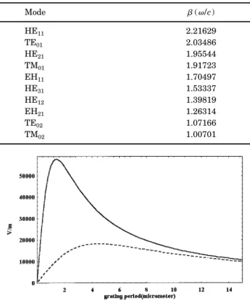
guided modes are shown in Table 2 in units of/c. By examining the coupled Equations (14), we note that the power transfer rate is proportional to␥jk. According
to Eq. (16), we can rewrite the coupling constant such that ␥jk⫽ 共1 ⫺␦jk兲 2 2c2⑀ 0j fjk共E0SC兲jk, (24) where fjk⫽ ⫺ 养Fj • Fk*Fj* •
冋
r13no 4 0 0 0 r13no4 0 0 0 r33ne4册
Fkda 养Fj • Fj*Fk* • Fkdais the modal field factor, with rjkbeing the element of the
electro-optic tensor, and (E0SC)jkis the space-charge field,
which depends on the period of the jth and kth modes’ photoinduced grating and the SBN impurity dopant density.6 In this example we have (E
0 SC)
jk⫽ (E0SC)kjand
fjk⫽ fk j. Figure 1 shows the SBN space-charge field as
a function of the photoinduced grating period for two dop-ant densities, ND⫽ 1017and 1016cm⫺3. When the
grat-ing period ⌳G ⫽ 1.409m and the dopant density ND
⫽ 2NA⫽ 1017cm⫺3, the SBN samples have a maximum
space-charge field E0SC⬇ 5.4 ⫻ 104V/m.
The upper-triangular half of Table 3 shows fjk/r13no
4,
which displays the difference between the bulk and the waveguide medium (for the bulk medium, this factor is unity). The modal field factor is zero between the TE and TM modes because FTE • FTM⫽ 0. We note that a
maximum value of the modal field factor is produced by the TE01 and TE02 modes and that a minimum value is Table 1. Cutoff Values of V Number
Mode (1) ncl⫽ 1 (2) ncl⫽ 1.45 (3) nclt ⫽ 2.346, nclz ⫽ 2.31 HE11 0 0 0 TE01 2.404826 2.404826 2.404826 HE21 3.277405 2.8926845 2.42447 TM01 2.496311 2.496311 2.4356962 EH11 3.831706 3.831706 3.831706 HE31 4.7534085 4.3963371 3.8615067 HE12 3.977474 3.977474 3.8808935 HE41 6.0751014 5.73888 5.174301 EH21 5.145449 5.1528398 5.1660751 TE02 5.520078 5.520078 5.5200781 HE22 6.1823798 5.8333314 5.5598849 TM02 5.730076 5.730076 5.5909392 EH31 6.3926285 6.4020849 6.4190246
produced by the EH11and TM02modes. The variation is
a result of the overlap integral of the modal field profiles. The lower-triangular half of Table 3 shows the photoin-duced grating period (⌳G)jk⫽ (⌳G)k j between any two
modes of the fiber in units of micrometers. According to the grating periods and Fig. 1, we note that the space-charge fields are in the range between 1.2⫻ 104
and 5.8⫻ 104V/m.
Table 4 shows the photorefractive coupling constants ␥jk between any two modes of this ten-mode fiber. We
note that coupling constants ␥TE,TM⫽ 0 between the TE
and TM modes because their wave functions are orthogo-nal: FTE • FTM⫽ 0. A slight difference between ␥jk
and␥kjis a result of the difference injandk(we recall
that j␥jk⫽k␥k j). According to our numerical
analy-sis, we find that modal wave-function contributions are more significant than those of the space-charge fields. We also note that the coupling constant between the HE31
and HE21modes is maximum because they have a higher
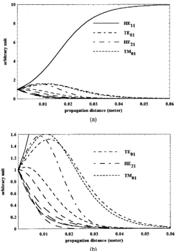
modal field factor and a higher space-charge field. Figure 2 shows the modal power as functions of z for ⌽ ⫽ ⫺/2. In the absence of absorption, we note that
PHE11is an increasing function of z in the fiber. We also
note that the HE11mode will gain virtually all the power
in a few centimeters. Three low-order modes, TE01,
HE21, and TM01, initially gain the power from
higher-order modes but eventually donate all the power to the fundamental mode HE11. All other modes are decreasing
functions of z [see Fig. 2(b)]. On the other hand, when
Fig. 1. SBN space-charge field as function of the photoinduced grating wavelength for two doped densities: ND⫽ 1017cm⫺3
(solid curve) and ND⫽ 1016cm⫺3(dashed curve).
Table 2. Propagation Constants of SBN Rod
Mode (/c) HE11 2.21629 TE01 2.03486 HE21 1.95544 TM01 1.91723 EH11 1.70497 HE31 1.53337 HE12 1.39819 EH21 1.26314 TE02 1.07166 TM02 1.00701 Table 3. fjkÕr13no
4 Factorsaand Grating Periods (⌳
G)jkb HE11 TE01 HE21 TM01 EH11 HE31 HE12 EH21 TE02 TM02 HE11 * 0.5002 0.6526 0.3156 0.4677 0.7221 0.2718 0.3871 0.4897 0.1087 TE01 2.836 * 0.4455 0 0.6431 0.3340 0.0910 0.3723 0.9580 0 HE21 1.972 6.479 * 0.3562 0.4455 0.8390 0.2394 0.3712 0.4141 0.1406 TM01 1.72 4.374 13.46 * 0.1624 0.2962 0.3542 0.2995 0 0.3895 EH11 1.006 1.56 2.054 2.424 * 0.3515 0.1313 0.6385 0.4200 0.0402 HE31 0.7534 1.026 1.219 1.34 2.998 * 0.2547 0.3135 0.2482 0.1421 HE12 0.6289 0.8081 0.9233 0.9913 1.677 3.806 * 0.1624 0.1227 0.1619 EH21 0.5398 0.6667 0.7432 0.7866 1.164 1.904 3.81 * 0.3506 0.0625 TE02 0.4495 0.5342 0.5822 0.6085 0.8124 1.114 1.576 2.687 * 0 TM02 0.4255 0.5006 0.5425 0.5652 0.7371 0.9775 1.315 2.009 7.958 *
aUpper-triangular half of the table.
bLower-triangular half of the table, in units of micrometers.
Table 4. Coupling Constantsa
HE11 TE01 HE21 TM01 EH11 HE31 HE12 EH21 TE02 TM02 HE11 * 109.3 263.9 110.3 128.4 311.0 88.52 71.42 77.75 30.87 TE01 119.1 * 55.25 0 191.1 94.93 23.45 85.97 189.6 0 HE21 299.2 57.50 * 31.31 154.7 560.1 142.3 117.3 90.82 80.34 TM01 127.5 0 31.93 * 20.40 150.7 294.9 58.03 0 274.1 EH11 166.9 228.0 177.4 22.94 * 128.0 55.18 274.6 129.5 16.79 HE31 449.5 126.0 714.3 188.5 142.3 * 169.2 180.0 95.72 175.7 HE12 140.3 34.12 199.9 404.4 67.28 185.6 * 82.20 53.00 228.5 EH21 125.3 138.5 181.6 88.07 370.7 218.5 90.99 * 138.8 64.42 TE02 160.8 360.1 165.7 0 206.1 137.0 69.14 163.6 * 0 TM02 67.95 0 156.0 521.9 28.43 267.5 317.3 80.81 0 * aIn units of micrometers.
the direction of the c axis is reversed and the propagation direction remains the same, the coupling coefficients re-verse their signs.12 In this case the two highest modes, TE02and TM02, will gain the power. Figure 3 shows the
modal power as functions of z for⌽ ⫽ ⫹/2. There is no coupling between the TE02and TM02modes because their
wave functions are orthogonal: FTE02 • FTM02⫽ 0.
6. CONCLUSION
A complete analysis for the mode coupling among guided modes in a photorefractive crystal PRC waveguide is in-vestigated, and the coupled equations in a two-mode PRC waveguide are analytically solved. A numerical analysis for the coupled equations of guided modes in a ten-mode PRC fiber is also presented. Based on the above analy-sis, we find that the power in a multimode waveguide can flow either to the fundamental mode or to the highest-order mode, depending on the direction of the crystal op-tical axis. Thus a PRC fiber can function like a mode converter. Such a PRC mode converter can also be em-ployed to eliminate the fan-in power loss in an optical interconnection.13
ACKNOWLEDGMENT
This work was partially supported by the National Sci-ence Council, Republic of China, under contract NSC 88-2215-E-009-006.
Address correspondence to Sien Chi at the location on the title page or by phone, 886-3-5712121, ext 56324; fax, 886-3-5716631; or e-mail, [email protected].
REFERENCES
1. G. Meltz, W. W. Morsey, and W. H. Gleen, ‘‘Formation of Bragg grating in optical fibers by a transverse holographic method,’’ Opt. Lett. 14, 823–825 (1989).
2. K. O. Hill, B. Malo, K. A. Vineberg, F. Bilodeau, D. C. Johnson, and I. Skinner, ‘‘Efficient mode conversion in tele-communication fibre using externally written gratings,’’ Electron. Lett. 26, 1270–1272 (1990).
3. H. G. Park and B. Y. Kim, ‘‘Intermodal coupler using per-manently photoinduced grating in two-mode optical fibre,’’ Electron. Lett. 25, 797–799 (1989).
4. C. Shi and T. Okoshi, ‘‘Analysis of fiber-optic LP01↔ LP02 mode converter,’’ Opt. Lett. 17, 719–721 (1992).
5. L. Solymar, ‘‘Theory of volume holographic formation in photorefractive crystal,’’ in Electro-Optic and Photorefrac-tive Materials, P. Gunter, ed. (Springer-Verlag, Berlin, 1987), Chap. 3, pp. 75–97.
6. P. Yeh, Introduction to Photorefractive Nonlinear Optics (Wiley, New York, 1993), Chap. 4, pp. 118–182.
7. A. Tonning, ‘‘Circularly symmetric optical waveguide with strong anisotropy,’’ IEEE Trans. Microwave Theory Tech. MTT-30, 790–794 (1982).
8. J. D. Dai and C. K. Jen, ‘‘Analysis of cladded uniaxial single-crystal fibers,’’ J. Opt. Soc. Am. A 8, 2021–2025 (1991).
9. P. Yeh, ‘‘Two-wave mixing in nonlinear media,’’ IEEE J. Quantum Electron. 25, 484–519 (1989).
10. G. P. Agrawal, Nonlinear Fiber Optics (Academic, San Di-ego, Calif., 1989), Chap. 7, pp. 173–177.
11. G. L. Wood, W. W. Clark III, M. J. Miller, E. J. Sharp, G. J. Salamo, and R. R. Neurgaonkar, ‘‘Broadband photorefrac-tive properties of self-pumped phase conjugation in Ce-SBN:60,’’ IEEE J. Quantum Electron. QE-23, 2126–2135 (1987).
12. L. Li, K. G. Chittibabu, Z. Chen, J. I. Chen, S. Marturunk-akul, J. Kumar, and S. K. Tripathy, ‘‘Photorefractive effect in a conjugated polymer based material,’’ Opt. Commun. 152, 257–261 (1996).
13. P. Yeh, ‘‘Reconfigurable optical interconnection,’’ in Inte-grated Optoelectronics for Communication and Processing, C. S. Hong, ed., Proc. SPIE 1582, 3–13 (1991).
Fig. 2. Modal power versus propagation distance for ten-mode SBN rod with⌽ ⫽ ⫺/2 and␥1k⬍ 0.
Fig. 3. Modal power versus propagation distance for ten-mode SBN rod with⌽ ⫽ ⫹/2 and␥1k⬎ 0.
![[2015-Fall] WNFA lab1 - CamCom](data:image/gif;base64,R0lGODlhAQABAIAAAP///wAAACH5BAEAAAAALAAAAAABAAEAAAICRAEAOw==)