i
國 立 交 通 大 學
資訊科學與工程研究所
碩
士
論
文
以階層式案例推論方法輔助建築平面考試試題設計
A Hierarchical Case-Based Reasoning Approach to Building
Schematic Exam Item Design
研 究 生:潘世恒
指導教授:曾憲雄 博士
ii
以階層式案例推論方法輔助建築平面考試試題設計
A Hierarchical Case-Based Reasoning Approach to Building
Schematic Exam Item Design
研 究 生:潘世恒 Student:Shish-Heng Pang
指導教授:曾憲雄 博士 Advisor:Dr. Shian-Shyong Tseng
國 立 交 通 大 學
資 訊 科 學 與 工 程 研 究 所
碩 士 論 文
A Thesis
Submitted to Institute of Computer Science and Engineering College of Computer Science
National Chiao Tung University in partial Fulfillment of the Requirements
for the Degree of Master
in
Computer Science June 2009
Hsinchu, Taiwan, Republic of China
iii
摘 要
隨 著 電 腦 及 網 路 科 技 的 進 步 , 藉 由 電 腦 及 網 路 的 學 習 評 量 稱 為 CBT (Computer-Based Testing) 已 成 為 一 個 趨 勢 , 對 美 國 建 築 師 考 試 (ARE , Architect Registration Examination)而言,電腦化測驗已普遍應用在考試 的各個項目,其中以圖形化(Vignette)測驗佔大多數,目的在藉由圖面的繪製 來測驗出知識整合的能力,而在本研究中,我們將專注於建築平面(Schematic Design)設計的項目。在試題的出題設計上因為是測驗高階的設計知識概念, 所以在出題上對老師是很困難的。他們通常需要去做複雜且多層次的考量, 定義且設計試題,以確保能有效的測驗出學生的能力,所以常常會花很多的 時間及成本。我們的目標是建立一個輔助出題系統去協助老師出題且能對之 前的考題再利用,讓出題不再是從無到有那麼的困難。目前考題的再利用方 面,往往是圖面的蒐集整理,沒有結構化的去對圖面內容做定義,以致於再 利用的程度有限。所以如何結構化的描述建築平面設計知識模型是一個很重 要的課題,而模型的描述能力、延伸性及操作能力是一個很重要的評估指標。 如何清楚的描述知識的特性,我們的概念是藉由專家的角度及電腦科學的技 術來設計我們的模型,HCBR(Hierarchical Case-Based Reasoning)的方法是 提出一個階層性的概念,來對知識做有層次的分類,以案例為基本單位加以 推 論 及 再 利 用 。 除 此 之 外 , 我 們 提 出 一 個 智 慧 型 的 搜 尋 條 件 產 生 器 (Intelligent Query Generator ,IQG),IQG 能有效協助老師對系統下搜尋 條件,藉由搜尋條件的增減的建議,能找到適合的案例,搜尋條件可當成考 題,而搜尋出來的案例可以當成改考卷的參考答案;其中我們所定義的搜尋 語言(Query language, QL)是協助 IQG 運作的重要角色,目的在有效描述輸 入的條件。最後,我們會提出系統設計上的建議,在實作方面,我們會實作 出建築平面比較器,並以問卷的方式,來驗證系統的成效。
iv
A Hierarchical CBR Approach to Building
Schematic Exam Item Design
Student:Shish-Heng Pang Advisor: Dr. Shian-Shyong Tseng Institute of Computer Science and Engineering
Nation Chiao Tung University
Abstract
With the growth of the computer and the Internet technology, the learning assessment via the computer and the Internet, called Computer-Based Testing (CBT) has become a trend. In the Architect Registration Examination (ARE) the CBT is applied in schematic design test item to assess students planning capability. In this paper we focus on schematic design test item of subject building planning in ARE. However, the design of test item for assessing high level knowledge is difficult for teachers. Since they usually need to concern complex situations to make sure the effectiveness of test, the creation of test item is usually time consuming and costly. Our goal is to construct a system to assist teachers in item generation by reusing desirable cases. However, the database of current design cases usually focuses on documentary collection for layout information and is ill-structure for design knowledge representation. Therefore, how to organize the design knowledge to represent multidiscipline and granularity property of building for reusing is an interesting and important issue. The expressive power, extensibility and manipulation of model are also our issue. To clearly represent the building properties for above issue, our ideal is to organize design attributes form experts' perspective by extending the layout with environmental context information. Accordingly, the Hierarchical Case-Based Reasoning (HCBR) approach is proposed to organize the knowledge granularities by hierarchical relations. Therefore, the Intelligent Query Generator (IQG) is proposed to support the verification of constraint rule during item design by iterative case retrieval process. If the designed constraint rules are too specific which means no case is retrieved, then the IQG will recommend the user release the constraint rules. With the IQG the teacher can easily generate the desirable test item. To evaluate the effectiveness and usability of proposed approach, the prototype system and ten test cases were implemented. The corresponding questionnaire analysis was applied and the result shows that the proposed approach has high satisfaction degree.
Keywords: Case-Based Reasoning, CBR, Schematic Design, Exam Item, Architectural Design
v
致謝
這篇論文的完成,首先要感謝我的指導教授,曾憲雄老師。在這碩士生 涯中,學習到最多的就是跟隨曾教授做研究的過程,在毫無頭緒時指引我方 向,在我感到迷惘時給予當頭棒喝,並讓我學習到知識工程領域的研究方法、 邏輯思考及如何表達的能力,這將使我終生受用不盡。同時也要感謝我的口 試委員,楊鎮華教授、袁賢銘教授和洪宗貝教授,他們給予了我相當多寶貴 的意見,讓本論文更有意義與價值。 再來要感謝的是翁瑞鋒學長,這段期間內,即使他很忙還是願意騰出時 間與我討論並給我建議,協助我修改論文,在他身上我學到了做研究的方法, 真的是非常謝謝他!還有實驗室的同窗們,惠君、靖雅、士緯、祖淵及啟珺, 在這兩年的時光裡,和你們互相扶持鼓勵,才能完成了這篇論文,能認識你 們真的很開心。還有其他在身邊鼓勵我的朋友們,雖然無法在此一一提及, 但我心裡真的非常感激有你們在我身邊。 最後要謝謝我最愛的家人和女兒姿廷,總在背後默默支持著我,為我打 氣鼓勵,是我能完成這篇論文的最大動力,真的非常謝謝你們。vi
Table of Content
摘 要 ...iii Abstract... iv 致謝 ... v Table of Content... vi List of Figures... x List of Tables ... xiList of Algorithms ... xii
Chapter 1 Introduction ... 1
Chapter 2 Preliminaries... 4
2.1 Architectural Exam Item ... 4
2.2 Schematic Design Modeling ... 7
2.3 Case-Based Reasoning ... 8
Chapter 3 Schematic Design of Case Representation ... 10
3.1 Multi-Layer Schematic Structure ... 10
3.2 Multidiscipline Schematic Attribute ... 11
3.3 Schematic Attribute Property ... 15
3.4 Schematic Case Representation...17
Chapter 4 Hierarchical CBR Schematic Design (HCBRSD)... 29
4.1 CBR Support Exam Item Design ... 29
4.2 Case Retrieval ... 30
4.3 Query Language and Intelligent Query Generator (IQG) ... 37
4.4 Case Adaptation...41
Chapter 5 Implementation and Design... 46
5.1 System Design... 46
5.2 Topology Similarity Implementation ... 50
5.3 Experiment ... 51
Chapter 6 Conclusion and Future work ... 55
Reference ... 56
Appendix A The Example of Exam Item... 58
Appendix B The Questionnaire of Schematic Pattern Retrieve... 62
Appendix C The Schematic Design Process... 68
vii
List of Figures
FIGURE 2.1THE ARE ENTRY WINDOW...6
FIGURE 2.2THE SCHEMATIC DESIGN EXAM WINDOW...7
FIGURE 3.1THE LANGUAGE STRUCTURE...11
FIGURE 3.2THE ARCHITECTURAL LANGUAGE...12
FIGURE 3.3THE TOPOLOGY OF ARCHITECTURAL...13
FIGURE 3.4THE SCHEMATIC DESIGN PROCESS...13
FIGURE 3.5THE LAYOUT OF ARCHITECTURAL EXAMITEM ...14
FIGURE 3.6THE LIMITATION AND REQUIREMENT OF DESIGN...17
FIGURE 3.7THE TRADITIONAL DESIGN USING OUR PROPOSE MODEL...18
FIGURE 3.8A CASE OF HCBR...19
FIGURE 3.9THE MAPPING BETWEEN FRAME AND ONTOLOGY...20
FIGURE 3.10THE SITE ONTOLOGY...21
FIGURE 3.11THE BUILDING ONTOLOGY...23
FIGURE 3.12AN EXAMPLE OF LABEL GRAPH AND ADJACENCY MATRIX...25
FIGURE 3.13THE ROOM ONTOLOGY...25
FIGURE 3.14THE CHARACTERISTIC OF FRAM...27
FIGURE 3.15AN EXAMPLE OF HCBR...27
FIGURE 4.1THE HIERARCHICAL CBR SCHEMATIC DESIGN...29
FIGURE 4.2THE HIERARCHICAL QUERY PROCESS...36
FIGURE 4.3AN EXAMPLE OF SIMILARITY CALCULATION...37
FIGURE 4.4THE IQG ...40
FIGURE 4.5THE CONFIGURATION PROCESS...42
FIGURE 4.6THE ELEMENTARY PROCESS...43
FIGURE 4.7THE AESTHETIC PROCESS...43
FIGURE 4.8THE ILLUSTRATION MODEL RESTORING...44
FIGURE 4.9AN EXAMPLE OF SPACE LEVEL CHECK...45
FIGURE 5.1THE WELCOME SCREEN...46
FIGURE 5.2THE LOCATION/SECTION QUERY DISPLAY...47
FIGURE 5.3THE BUILD CHARACTERISTIC QUERY DISPLAY...47
FIGURE 5.4THE CONFIGURATION QUERY DISPLAY...48
FIGURE 5.5THE INFORMATION DISPLAY...48
FIGURE 5.6THE MODIFY TOOL DISPLAY...49
FIGURE 5.7THE ITEM EDITING SCREEN...49
FIGURE 5.8AN EXAMPLE OF SPATIAL ENCODING...50
FIGURE 5.9THE USER INTERFACE...50
FIGURE 5.10AN EXAMPLE OF SPATIAL ENCODING...51
FIGURE 5.11THE SCREEN OF INTERPRETER...51
FIGURE 5.12THE RESULTS OF CASE RETRIEVE (GROUP 1) ...53
viii
List of Tables
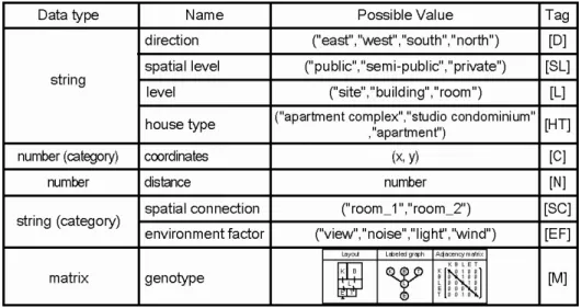
TABLE 3.1THE DATA TYPES OF CASE...20
TABLE 3.2THE CONSTRUCTION CHARACTERISTIC OF BUILDING...22
TABLE 3.3THE LOOK UP TABLE OF BUILDING CHARACTERISTIC...23
TABLE 3.4THE RELATION TYPE OF SPACE...24
TABLE 3.5THE COMPONENTS OF FRAME...26
TABLE 3.6THE EXPRESSIVE POWER...28
TABLE 3.7THE EXTENSIBILITY...28
TABLE 4.1THE MAPPING TABLE OF DATA TYPE AND SIMILARITY FUNCTION...31
TABLE 4.2THE DESCRIPTION OF QL SYMBOLS...38
TABLE 5.1THE QUESTIONNAIRE PATTERNS...52
ix
List of Algorithms
ALGORITHM 3.1ONTOLOGY-TO-FRAME ALGORITHM...20
ALGORITHM 4.1NCMATCH...33
ALGORITHM 4.2RCMATCH...33
ALGORITHM 4.3NSMATCH...35
ALGORITHM 4.4RSMATCH...35
1
Chapter 1 Introduction
With the growth of the computer and the Internet technology, the learning assessment via the computer and the Internet, called Computer-Based Testing (CBT) has become a trend. The CBT can be used in assessment of high level knowledge. For example, in the Architect Registration Examination (ARE) the CBT is applied in schematic design test item to assess students planning capability. Thus, the CBT is getting more important.
In ARE, the test of vignette can be divided into three categories which are site planning, building planning and building technology. In this paper, we focus on schematic design test item of subject building planning in ARE. However, the design of test item for assessing high level knowledge is difficult for teachers. Since they usually need to concern complex situations to make sure the effectiveness of test, the creation of test item is usually time consuming and costly.
With our observation, the schematic design exam in building planning usually consists of multidiscipline and different granularity of constraints for building properties. While the experts or senior teachers create the test item, they usually refer to the existing design cases to construct the new one. Thus, our goal is to assist teachers easily creating the item by reusing the cases. However, the database of current design cases focusing on documentary collection for layout information is ill-structured for schematic designing knowledge representation. Therefore, we aim to reorganize the knowledge representation to describe the
2
multidiscipline and several granularity properties of building for schematic designing knowledge reusing. Thus, the expressive power, extensibility and manipulation of knowledge representation model are our issues.
To clearly represent the building properties for above issue, our idea is to organize design attributes form experts' perspective by extending the building layout with more environmental context information. While experts design buildings, they are concerned with the followings: property of zoning and segment, type of building, configuration of rooms. Accordingly, the Hierarchical Case-Based Reasoning approach is proposed to organize the knowledge granularities by hierarchical relations where each layer denotes attributes of different granularties. In addition, the multidiscipline building properties are classified into three types of attributes: usage, topology and constraint rule.
Accordingly, the similarity functions are designed for different attribute types to provide flexible case retrieval service. The Intelligent Query Generator (IQG) is proposed to support the verification of constraint rule during item design in iterative case retrieval process. To assist teachers creating the test item, if the designed constraint rules are too specific to retrieve no cases, then the IQG will recommend the user to release the constraint rules. If the designed constraint rules are too general and too many cases are retrieved, then the IQG will recommend the user to add more constraint rules. With the IQG, the teacher can easily generate the desirable test item.
To evaluate the effectiveness and usability of proposed approach, the prototype system and ten test cases were applied. The corresponding questionnaire
3
analysis was applied and the result shows that the proposed approach is usable for assisting in item designing.
The remainder of the article is organized as follows. In Chapter 2, we introduced some related works about the ARE and CBR. In Chapter 3, we surveyed the schematic design on architectural domain. In Chapter 4, the HCBRSD scheme was introduced. In Chapter 5, the system implementation and experiments were discussed. Finally in Chapter 6, we provided the conclusion and future work for this research issue.
4
Chapter 2 Preliminaries
In this chapter, Architectural Registration Examination (ARE) and exam item are introduced first. Second, we emphasize upon configuration of architectural space and analyses how the existing papers model architectural plans and where does it apply. Finally, we will introduce Case-Based Reasoning (CBR) to explain how to implement former cases to solve current problems.
2.1 Architectural Exam Item
Architectural Exam Item is a graphic/layout-based subject. Due to complicated derivation and certain conditions constraints, several iterations of inference are needed to produce results in physical layout until the result is satisfied. As teachers normally solve problems based on their past experience, CBR is suitable to be applied.
Nowadays, architectural exam in most of the countries is pen-and-pencil format, except for US, which is the pioneer of computerizing the exam. The exam consists of multiple-choice questions and graphic vignettes two parts and total of 9 business exams are included in contents.
(i) Multiple-choice Questions (MCQ)
MCQ is carried out by using mouse to choose for options, which consists of six subjects : Pre-design, General Structure, Lateral Force, Mechanical and Electrical System, Materials and Method, and Construction Documents and Service.
5
The number of questions for MCQ is fixed, for example, 90 questions for lateral force subject, while 120 questions for the remaining five subjects. Every test for each subject has different time limit and duration.
(ii) Vignettes
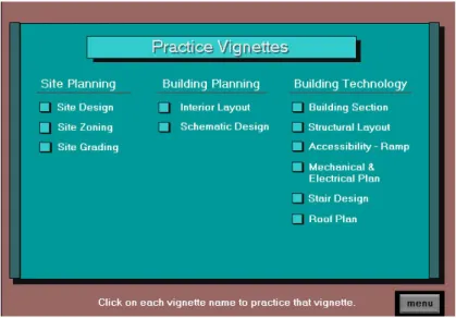
Graphic Divisions consist of three parts, Site Planning, Building Planning and Building Technology. There are 15 steps of vignettes to test the knowledge, skills and architectural ability in different aspects of the exam participants. Examinee are required to answer the questions based on programs and regulations. Belows are the list of vignettes of each graphic division.
Architect Registration Examination (ARE) of America : Part 1 : Site Planning
Site Design Side Zooning Side Grading Part 2 : Building Planning
Interior Layout
Schematic Design
Part 3 : Building Technology Building Section Structural Layout Accessibility - Ramp
Mechanical & Electrical Plan Stair Design
6
Roof Plan
Figure 2.1 The ARE entry window
Schematic Design of Building Planning
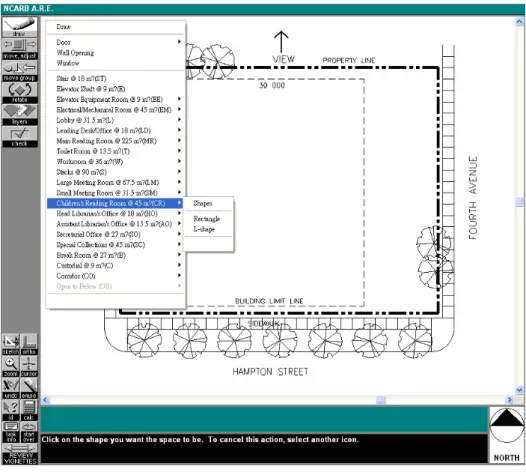
In this research, we will focus on the item of schematic design which is one of the important subjects for architectural beginner and national exam. The purpose is to test the ability of student on space arrangement and organization, in which the basement analysis, relation of space organization, space volume dimension and the interaction between space and environment are needed to be considered. The key point is to test the ability of student on integrated thinking and problems solving in different point of view.
In Figure 2.2, a screen shot of mock exam provided to exam participants to practice and get familiar with the exam shows the practicing software of schematic design provided by NCARB (National Council of Architectural Registration Boards).
7
Figure 2.2 The schematic design exam window
2.2 Schematic Design Modeling
We have surveyed several researches about the architectural space modeling as follows.
(1) Small-graph matching and building genotypes [8]: This paper discussed an application on "Building-genotype and similarity" and used bubble diagram to model spaces.
(2) A graph-based algorithm for extracting units and loops from architectural floor plans for a building evacuation model [21]: This paper mainly discussed how to calculate the evacuation directions of exit and also used bubble diagram to model spaces.
8
(3) Visual knowledge specification for conceptual design [12]: This paper mainly discussed the "Knowledge ontology and design rules" and used UML to model spaces.
(4) A geometric modeling framework for conceptual structural design from early digital architectural models [13]: This paper is mainly an application on "Integrated architectural-structure representation" and used UML to describe spaces.
Through our observation, 2 types of method are often used to model architectural space organization (1) Bubble diagram (2) UML, these methods can only be applied to specific application. Structure of spatial description and extension can only be achieved by UML; therefore, bubble diagram is limited on specific plans. Both of the methods above are not possessed with the ability of inference.
2.3 Case-Based Reasoning (CBR)
Case-Based Reasoning [5] [6] [7] [11] is attempted to solve new problems through revising the solutions of former cases, which is searching similar cases to find solutions of former problems and transform them to become the solutions of new problems. For example, when architects are doing architectural design, they will develop their architectural plan by referring to similar design conditions or trying new designs; if they could produce their plan successfully, then we would memorize the architectural plan and try to solve similar situation by using this design next time. CBR is a concept produced based on this idea; therefore it is a
9
well knowledge management technique that can help us to derive the develop circumstances of new case according to former case experience.
By using Case-Based Reasoning, the first step is to describe a problem (presentation) and retrieve the most similar case from case base (Retrieval). Because the retrieved case will not be totally identical with current case, the adaptation will be applied in light of the case solution to verify the revised solution with user and environment, and the verified case will be added into case-base if required.
Therefore, case-base reasoning is a process that is closer to human decision policy; it can combine new knowledge to current case-base automatically, and create case-base if required.
When case-base reasoning concept is used on architectural exam generation, we can presume new solutions by referring to former solutions.
10
Chapter 3 Schematic Design of Case Representation
The first of the design process on school is schematic design phase where floor plans, sections, elevations and building systems are created. It is the footprint of the building which in order to house all of the building functions.
3.1 Multi-Layer Schematic Structure
Suitable case can be found immediately and effectively while searching data. Besides, it also can be found by different point of view and skillful inference. Thus, the knowledge of how to design house by expert can be specified as the criteria of three views.
(1) The point of view on location/section, e.g., business section, residential district, etc.
(2) The point of view on building type, e.g., mixture of residence, apartment complex, etc.
(3) The point of view on configuration, e.g., 3* bedroom, 1* living room and 1 * kitchen.
According to our observation, HCBR can be separated into 3 layers.
Layer1 : Site layer Layer2 : Building layer Layer3 : Room layer
11
3.2 Multidiscipline Schematic Attribute
3.2.1 Architectural LanguageFrom theory by Perice and Morris [17], the analysis of symbols structure is to discuss the relations between the elements that construct the symbols. This relation can be divided into three layers based on its properties, which are qualisign, sinsign, and legisign. The study of such relations is syntactics. Language expert from M.I.T., Chomsky, has the most influence on language symbol study. His language structure theory included two layers, deep structure and surface structure. As shown in Figure 3.1, the surface structure is evolved from deep structure through generative rule.
Figure 3.1 The language structure
According to our observation, we can consider architectural as a language [9] that can be divided to Syntactic, Semantic, Pragmatic, as shown in Figure 3.2. (1) Syntactic: Rules of space topology. For example, the sequence of space is
12
(2) Semantic: Meaning of space. For example, in the view of physics theory, entrance is not suitable to be placed opposite of the door of balcony at the back.
(3) Pragmatic: The real meaning of space topology in current situation. For example, small suite is more popular in city but less popular in countryside.
Figure 3.2 The architectural language
3.2.2 Schematic design flow
Architectural plane [2] [3] [10] [20] is a series of space combination. This combination represents the relation and interaction between spaces, and it is called genotype. Space area including external environment (dimension, scale) which affects the location and appearance of the building is called phenotype. Figure 3.3 shows a typical genotype and has different representation on phenotype due to external factors.
(1) Genotype :
Genotype is a general term for all of the genes in human body [15]. It is also termed as inheritage type, is the sequence or combination of human genes, or the inheritage materials in cells.
13
Figure 3.3 The topology of architectural
(2) Phenotype :
Phenotype is the external appearance and behavior of human body. It is also termed as surface type, is the external appearance of inheritage characteristics.
Schematic design process
Through above, we can know that schematic design process is the process transformed from genotype to phenotype. Please refer to Appendix C in details.
Figure 3.4 The schematic design process
Step1 : Define symbol. Every space has a symbol to express the number and area of the space.
Step2 : Draw bubble diagram. Bubble diagram expresses the relation between spaces. Depending on activities and space topology, it has different combinations.
14
Step3 : Size the space. Define the dimension of space area, scale relations and fill in the node of bubble diagram.
Step4 : Locate the space. Define the relation between space and external factors. For example, if there is a park outside the building, living room should be opposite of the park.
Step5 : Create space function. Space topology should fulfill its ability on carrying out its function and should satisfy artistic and structural requirements. According to our observation, we classify the exam item to 4 parts:
(1) Subject (2) Usage (3) Topology (4) Constraint rule
A simple sample of exam item
Based on design process above, we classify the exam item into 4 parts as below.
15
(1) Subject :
(1-1) My single suite. (2) Usage
(2-1) I want a seated north and heading south home.
(2-2) My living room and bed room are possessing good view, and far away from noise.
(2-3) I hope that my bed room may not be smaller than 18 m2.
(3) Topology.
(3-1) My house entry should be away from road.
(3-2) I hope to connect that all spaces through living room. (3-3) I can see a distant place when I am washing dishes. (4) Constraint Rules
(4-1) On account of the consideration of private authority, I hope that the private level of space from entrance to inner space can be discriminated to semi open, open and private.
3.3 Schematic Attribute Property
The requirement of design can be classified to interior requirement and exterior requirement; for exterior requirement, physical environment (e.g., wind, sun light) and the interaction between space and environment (e.g., view, noise) are needed to consider. For interior requirement, the consideration will change according to different construction types (i.e., the space design of residence house and building are different), we will discuss the requirement of residence in this section.
16
1. External (environment)
(1) Uniformity : no direct facing can be divided to light and wind (i) Light, i.e., when there is only one window open up inside a room, it will produce glare phenomena (ii) Wind, i.e., Draft occurs when the entry and exit of room (door or window) are aligned.
(2) Orientation : there are absolution and none absolution direction (i) Absolution direction :
Light, i.e., room with a western exposure. Wind, i.e., northeasterly season wind.
(ii) None Absolution direction, e.g., view, noise, etc.
2. Internal (Design required of small house)
(1) The sequence of syntactic, i.e., It is not advisory to have kitchen ahead of bedroom.
(2) Size of entrance. Places after the main entrance must only be vestibule, living room or porch.
(3) Room inside room is prohibited, i.e., Study room in the bedroom. (4) Not more than one door in a room (closed space).
(5) Toilet should not exist in the kitchen.
(6) Toilet is prohibited to face directly with master bedroom. (7) Not advisory to place toilet just beside master bedroom door. (8) Gas stove is placed near window.
17
3. Degree of space privacy
Degree of space privacy can be divided into 4 categories
(1) Open, e.g., living room, tunnel, etc.
(2) Semi open, e.g., dining room, kitchen, etc. (3) Semi private, e.g., intermediate space.
(4) Private, e.g., bed room, study room, toile, etc.
Based on the degree of space privacy, the sequence of space is Open area >
semi open > semi private> private.
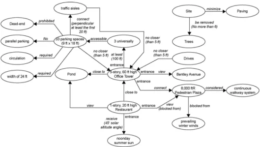
As shown in Figure 3.6, we can use cognitive map [14] to indicate the relation of requirement including limit of design and requirements.
Figure 3.6 The limitation and requirement of design
3.4 Schematic Attribute Property
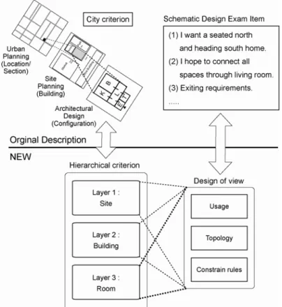
As mentioned above, we represent case in 3 layers including location/section, building type, configuration, where each layer can be divided to 3 views including
18
usage, topology and constraint rule as shown in Figure 3.7. We focus on schematic design here and only the usage of the design of view of layer1 and layer2 will be discussed.
Figure 3.7 The traditional design using our propose model
Definition 3.1 Case in a three-tuple
Hierarchical CBR Structure, HCBR ={L, N, R}, where 1. L = {layer1, layer2, …, layern} is a point of view.
2. N={node1, node2,…,noden} is a member of layer.
19
Figure 3.8 A case of HCBR
(1) Layer (L)
Layer 1 : Site characteristic level, i.e., layer1 in Figure 3.7 : location /section which explains the degree of site usage and important information of layer 2 and layer 3 respectively.
Layer 2 : Building level, i.e., layer2 in Figure 3.7 : building type which explains the types of building, containment of space, etc.
Layer 3 : Room level , i.e., layer3 in Figure 3.7 : Configuration which explains the characteristic of each room, e.g., area scale, external requirement.
(2) Node (N)
Each node expressed by frame knowledge is an object coming after instance, based on the consideration of extension; we have ontology to explain category that can produce object. The ontology owns “a-kind-of” and “IS-A” relationships between the classes of comparison in future [1].
20
Figure 3.9 The mapping between frame and ontology
Table 3.1 The data types of case
Algorithm 3.1 Ontology-to-Frame Algorithm
Input: Input related ontology according to layer. Output: Frame
Step 1. List the knowledge case set for the ontology, ontology knowledge classes contained classes, and relationship.
Step 2. Choose related attribute according to requirement. Step 3. Copy attributes to frame slot.
21
(3) Edge (E): Has-part. Currently, we only have one type of relationship between frames.
Detailed explanation for each layer is listed below:
Layer 1 : Site characteristic Layer
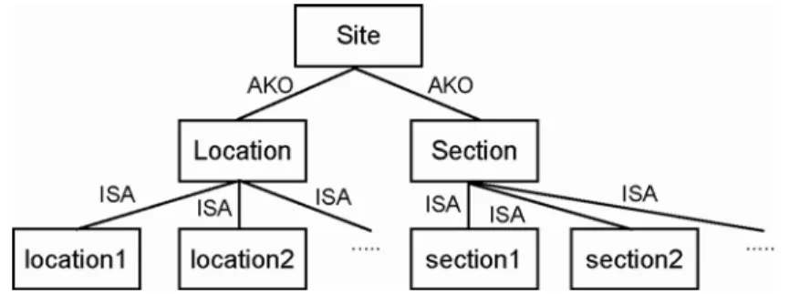
The main function of site characteristic layer is to describe the location as shown in Figure 3.10; besides, information of layer2 and layer3 are also included e.g. space arrangement, squire size. Therefore, information can be completely received and compared when searching on first stage, required property of first stage are listed below.
(1) The character of base, e.g., zone.
(2) The intensity of usage, e.g., Building Bulk Ratio, Coverage Ratio, etc. (3) The construction style, e.g., house, office building, etc.
(4) The space arrangement, e.g., 2 x Bedroom and 1 x Living room, (5) The square size
(6) The using floor
Figure 3.10 The site ontology
22
This stage is mainly explaining the classification of architectural building as shown in Figure 3.11, the required property of stage 2 is listed below.
(1) The construction style, e.g., house, office building, etc.
(2) The space arrangement, e.g., 2 x Bedroom and 1 x Living room. (3) The square size and using floor
(4) The construction character = (E, V, M, R, L, C, P, I, G)
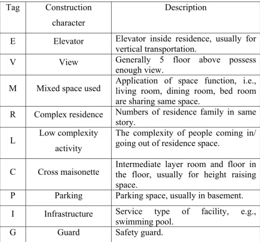
The main explanations of construction character are showed in Table 3.2.
Table 3.2 The construction characteristic of building
Tag Construction character
Description
E Elevator Elevator inside residence, usually for
vertical transportation.
V View Generally 5 floor above possess
enough view.
M Mixed space used Application of space function, i.e., living room, dining room, bed room are sharing same space.
R Complex residence Numbers of residence family in same
story.
L Low complexity
activity
The complexity of people coming in/ going out of residence space.
C Cross maisonette Intermediate layer room and floor in the floor, usually for height raising space.
P Parking Parking space, usually in basement.
I Infrastructure Service type of facility, e.g.,
swimming pool.
G Guard Safety guard.
In Table 3.3, the characteristic of different construction types are explained, i.e., town house contains the characteristic of low complexity activity and infrastructure required.
23
Table 3.3 The look up Table of building characteristic
(5) The view direction (6) The noise direction
Figure 3.11 The building ontology
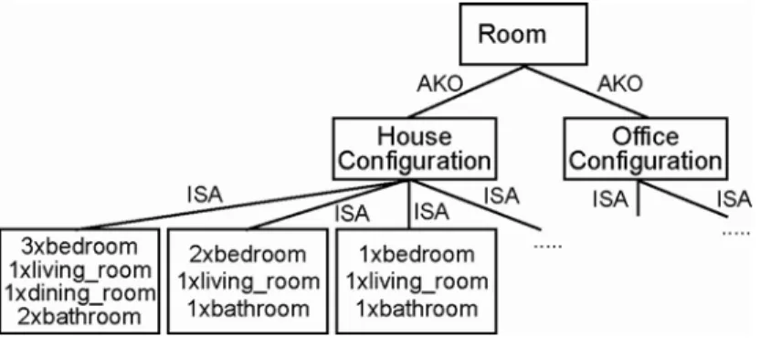
Layer 3 : Room Layer
This stage is applied mainly to describe the configuration of space, Figure 3.13, describes the characteristic of each space and the relations of spatial connection. The required property of stage 3 is listed below.
(1) The name of space (2) The area size
24
(3) The private level
(4) The space required, e.g., view, wind, etc. (5) The space refuse, e.g., noise.
(6) The relation type = (C, D, A, P, I), Space connection rule can be divided into different types as below.
Table 3.4 The relation type of space
Tag Type Descript
C Connection Direct connection characteristic between spaces, i.e., master bed room will connect with a bath room space.
D Disconnection Disconnection characteristic between spaces, i.e., dining room will not connect with toilet.
A Adjacency Adjacency characteristic, e.g., living room, dining room and kitchen will be adjacent to each others.
P Dependence Possess a visible requirement but can not reach directly, i.e., living room needs a view, so it needs to face towards park.
I Independence
Possess an invisible requirement and also cannot reach directly, i.e., avoid from noise, living room doesn’t need to face towards road.
Definition 3.2 Adjacency matrix
The adjacency matrix of a finite directed graph G on n vertices is the n × n
matrix where the nondiagonal entry aijis the number of edges from vertex i to
vertex j, and the diagonal entry aiiis either twice the number of loops at vertex
i or just the number of loops. There exists a unique adjacency matrix for each graph, and it is not the adjacency matrix of any other graph. In the special case of a finite simple graph, the adjacency matrix is a (0,1)-matrix with zeros on its diagonal. (Reference from WIKI)
25
Figure 3.12 An example of label graph and adjacency matrix
(7) The center coordinate
(8) The relative distance to center coordinate of house
Figure 3.13 The room ontology
Detailed explanation of node is listed below:
Frame-Based Knowledge Representation
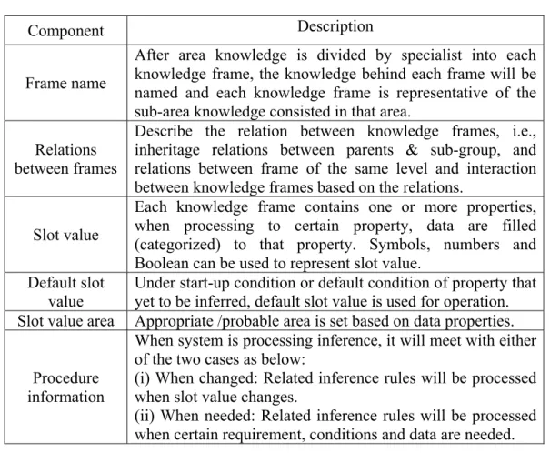
Frame-Based Knowledge Representation proposed by Mawin Minsky in 1975 is primarily used to develop new specialist system. Frame-Based Knowledge Representation mainly consisting of frame name, relations between frames, slot value, default slot value, slot value area/field, and procedure information (Negnevitsky, 2002) is used to describe our knowledge.
26
Table 3.5 The components of frame
Component Description
Frame name
After area knowledge is divided by specialist into each knowledge frame, the knowledge behind each frame will be named and each knowledge frame is representative of the sub-area knowledge consisted in that area.
Relations between frames
Describe the relation between knowledge frames, i.e., inheritage relations between parents & sub-group, and relations between frame of the same level and interaction between knowledge frames based on the relations.
Slot value
Each knowledge frame contains one or more properties, when processing to certain property, data are filled (categorized) to that property. Symbols, numbers and Boolean can be used to represent slot value.
Default slot value
Under start-up condition or default condition of property that yet to be inferred, default slot value is used for operation. Slot value area Appropriate /probable area is set based on data properties.
Procedure information
When system is processing inference, it will meet with either of the two cases as below:
(i) When changed: Related inference rules will be processed when slot value changes.
(ii) When needed: Related inference rules will be processed when certain requirement, conditions and data are needed. From the Table above, we know that frame name which is the same as category name contains its properties and methods. When inference is processed, knowledge frames will not affect each other but operate independently. From the interaction between frames, information can be transferred between frames are possible, and the description of relations between frames, is similar with interaction among the same level and inheritance relation between different levels. Therefore, we know that frame-based Knowledge Representation has the properties of object encapsulation and inheritance. In AI (Artificial Intelligence) area, this Representative method is also termed as object knowledge representative method. So far both represent the same method.
27
Figure 3.14 The characteristic of frame
Finally, we can use a simple example to explain our mode, as shown in Figure 3.15.
Figure 3.15 An example of HCBR
Evaluation
After modeling the architectural plans knowledge, we can evaluate them in terms of different aspects, which included expressive power, the extensibility and operative. HCBR is a hierarchical CBR framework, which is the method commonly used by expert system, and has good performance on expressive power, as shown in Table 3.6. The performance of extensibility is built up hierarchical; therefore the extension of layer is very flexible and also possess acceptable performance on the extension of frame attribute, as shown in Table 3.7.
28
Eventually, based on the operative, algorithm and method can be embedded to attribute and infer through trigger due to the inference ability of the frame.
Table 3.6 The expressive Power
Table 3.7 The extensibility
As a comprehensive view, our model is a knowledge model represented by ontology-based method, so that it can have well performance on knowledge description, flexibility of extension and inference.
29
Chapter 4 Hierarchical CBR Schematic Design
(HCBRSD)
4.1 CBR Support Exam Item Design
The Hierarchical CBR Schematic Design is based on CBR framework [4] [18] [19], and the structure of frames is used to express knowledge. This can be a kind of object inheritance, and also can be used for derivation, so it is widely used by experts. From system operation of CBR structure, requirements are first set and relevant floor plans are taken out from data storage. After that, the system will retrieve several of the floor plans, called case retrieval. The user chooses to use tools provided by system to facilitate changes, is called case adaptation (include case reuse and case revise) and finally, adapted file will be set as exam paper and stored in data storage again, which is termed as case retain.
30
4.2 Case Retrieval
In the similar appraisal's situation, the system will obtain the preliminary detailed list case that is similar to the new question in the case storehouse. In this detailed list's situation, the arrangement will exist in the range of the similar score. If in the similarity grading past situation's threshold value, this case will be removed from the name list. Then, the system or the user may decide that in this kind of situation, is most similar and the best for further analysis.
Reminder is a key component of analogical reasoning through cases: in other words, a person or computer must be reminded of the appropriate case at the right time (Tsatsoulis and Williams, 2000). Retrieval is an action to recall a case in CBR. By retrieving a case from memory, a CBR system must decide which is the most appropriate case for current status based on the comparison of the degree of similarity. Therefore, the recall cases are dominated by similarity assessment and retrieval will be greatly influenced by the way the case is organized.
4.2.1 Similarity function
Similarity is used when indicating a connection between two objects [16]. Designers always compare the similarity of architectural elements to solve design problem as well as generate ideas during design process. For example, in the case of the Frank House designed by Peter Eisenman, the idea of “layering” comes from the similar form composition of the Schroder House designed by Gerrit Rietveld. So the layer of similarity is important for associating ideas. Each layer contains different data type, user can design the similarity function according to different data type, the mapping Table as shown in Table 4.1.(i) Category-based
31
Feature Similarity (CBFS) is for attribute comparison, (ii) Coverage Similarity (CS) is for query topology comparison, (iii) Sequence Similarity (SS) is for spatial sequence comparison, (iv) Complete Case Similarity (CCS) is for whole case comparison.
Table 4.1 The mapping Table of data type and similarity function
(1) Category-based Feature Similarity (CBFS) (Jaccard similarity coefficient)
Definition 4.1 Category-based Feature Similarity (CBFS)
FVA is the Feature Value of Feature A in one case and FVA’ is the Feature
Value of Feature A in the compared case.
Example 4.1 A A' A A' |FV FV | CBFS= |FV FV | I U
32
(2) Coverage Similarity (CS)
The case is similar to the composition of the coverage and sequence similarity. Coverage similar to a similar number of genotypes refers to the ideal model case between genotype and genotypes compared to the case library cases, as well as the type of means of sequence similarity between the ideal task for the genotype and genotype compared to the case database case. In order to calculate the topological similarity of the cases, we must work to find a similar comparison of the expectations of the cases, genotype and type of the first, and take them as the same situation, the calculation of similar genotypes. The physical meaning of the scope of coverage is comparing to a number of similar tasks on the total number of tasks required for the tasks or genotype flow (depending on the different circumstances), which is defined as follows:
Definition 4.2 Coverage Similarity
1.CS = NCS * RCS is the coverage similarity between the query desired genotype pattern and the compared genotype, where
NCS is the coverage similarity of node (room).
RCS is the coverage similarity of relation (connection). 2.
,where
NCMatch() is the node (room) coverage, as shown in Algorithm 4.1. TNNQ is the total number of nodes in the queried space.
3.
, where
RCMatch() is the relation (connection) coverage, as shown in Algorithm. TNRQ is the total number of relations in the queried relation.
NCMatch(Px) NCS= TNNQ RCMatch(Px) RCS= TNRQ
33 Example 4.2 (a) Example 4.2 (b) Algorithm 4.1 NCmatch Input: Px Output: Match Definition of Symbols:
CTi: The Compared spatial sequence i in the compared case
Step 1. Compare Px with the spatial sequences in the case , if Max( Similarity (Px,CTi) ) > threshold, then set (Px, CTm) a case pair and set Match = 1, else Match = 0
Step 2. Return Match
Algorithm 4.2 RCmatch
Input: Px Output: Match
Definition of Symbols:
CTi: The Compared spatial sequence i in the compared case
Step 1. Compare Px with the spatial sequences in the case , if Max( Similarity (Px,CTi )) > threshold, then set (Px, CTm) a case pair and set Match = 1, else Match = 0
34
(3) Sequence Similarity (SS)
For sequence similarity, the main idea is to find similar possible sequence, where the possible sequence is the combination of every two genotypes in case. For example, there are 3 combinational pairs A->B, B->D, and A->D for task flow A->B->D. In order to calculate sequence similarity, first step is to find similar sequence pairs, which means two A->B and A'->B', A->B is in desired task flow and A'->B' is in the compared task flow, where (A, A') and ( B, B') are two similar case pairs. The sequence pair similarity is the similarity average of 2 similar cases which is showed in Example 4.3, and the overall sequence similarity for a case is to equalize each similar sequence pair among all possible sequence. The definition is shown as follows:
Definition 4.3 Sequence Similarity
1. SS = NSS * RSS is the sequence similarity between the query desired room private level and the compared genotype, where
NSS is the sequence similarity of node (room).
RSS is the sequence similarity of relation (connection). 2.
,where NSMatch() is shown in Algorithm 4.3
TNNS is the total number of nodes in all cases. 3.
,where RSMatch() is shown in Algorithm 4.4
TNRS is the total number of relations in all cases. NSMatch(Px) NSS= TNNS RSMatch(Px) RSS= TNNS
35
Sq = (ST, DT) is the possible sequence generate from the query desired flow
ST ={t1, t2,.. tn} is the source genotype in genotype sequence
DT ={t1, t2,.. tn} is the destination genotype in genotype sequences
Example 4.3 (a)
Example 4.3 (b)
(4) Complete Case Similarity (CCS)
Algorithm 4.3 NSmatch
Input: Sq
Output: NSMatch
Step 1. Find if there is a matched sequence node in the compared case spatial sequence, if found then go to step 2, else end.
Step 2. NSMatch = ( TSSimilarity(ST) + TSSimilarity(DT) ) / 2 Step 3. Return NSMatch
Algorithm 4.4 RSmatch
Input: Sq
Output: RSMatch
Step 1. Find if there is a matched sequence relation in the compared case spatial sequence, if found then go to step 2, else end.
Step 2. RSMatch = (TSSimilarity(ST)+ TSSimilarity(DT)) / 2 Step 3. Return RSMatch
1/3, 1/3
1/3, 1/6
36
In complete case retrieval, a complete case similarity is calculated to retrieve an integral case, which is most similar to, desired case, in which both cases featuring table similarity and case genotype are used. For the case feature Table, it means to find out the average similarity between each feature Table. The complete case similarity is defined as below:
Figure 4.2 The hierarchical query process
(i) SIM_Layer1 (Case_q, Case_n) = ∑CBFSn(Case_q, Case_n) (ii) SIM_Layer2 (Case_q, Case_n) = ∑CBFSn(Case_q, Case_n)
Algorithm 4.5 Similarity comparison process
Input: Case
Output: Case Number
Step 1. Test if similarity Layer1 of Retrieved Case < threshold. True -> Return NULL
Step 2. Test if similarity Layer2 of Retrieved Case < threshold. True -> Return NULL
Step 3. Test if similarity Layer3 of Retrieved Case < threshold. True -> Return NULL
37
(iii)SIM_Layer3(Case_q,Case_n)=∑{CBFSn(Case_q, Case_n)+CSn(Case_q, Case_n) + SSn(Case_q, Case_n)}
Example 4.4
Figure 4.3 An example of similarity calculation
4.3 Query Language and Intelligent Query Generator (IQG)
Query language (QL)
Based on the concept above, we define a set of regular grammar, called the Query Language (QL), where the grammar rule of QL can be used to model the
38
schematic query, the non-terminals of QL represent the query run-time status, and the terminals of QL represent the actions the examinee can perform.
Definition 4.4 Query Language
Query Language is a 5-tuple, QL= (N, ∑, P, S, γ), where
1. N is a finite set of non-terminal, which represents the run-time status of specific query.
2. ∑ is a finite set of terminals, which represents the actions that the query can perform, e.g., attribute select.
3. P is a finite set of production rules, which represents the action performed by the query and the next run-time status of specific query. A production rule needs to satisfy one of the following forms..
4. S is the starting symbol, which represents the initial run-time status.
5. γ is a finite set of action symbols, which is defined on ∑ to trigger corresponding action routine.
Table 4.2 The description of QL symbols
Type Symbol Descript
S The starting query
symbol. Non-terminal
Q The query symbol.
AND The Boolean operation
symbol.
OR The Boolean operation
symbol.
. The location symbol.
<LAYER> The layer of HCBRSD.
<FRAME> The frame of HCBRSD.
Terminal
39
The production rule of QL S -> S | Q
Q -> Q AND Q | Q OR Q
Q -> <LAYER>. < FRAME >. <ATTRIBUTE_CONSTRAINT>
Example 4.5 The QL for User Interface
SELECT_WHERE
( layer1.building_type == “studio condominium” OR layer1.building_type == “apartment complex”) AND layer1.square_meter < 64 AND
layer1.square_meter > 30 AND
layer1.space_contain == {L, B, T} AND ( layer2.characteristic == “mixed space used” OR layer2.characteristic == “low complexity activity” OR layer2.characteristic == “cross maisonette” OR
layer2.characteristic == “guard” )
Intelligent Query Generator (IQG)
When there are too many conditions of query, it is difficult to find a suitable case. However, a limited number of conditions will generate a lot of cases, which require filtration of these cases. One needs to accurately specify the conditions to domains to find the most suitable case. Therefore, we propose a set of query language which can convert our query in use to condition-based, for the ease of
40
system operation. After that, the conditions set can be converted to exam questions. The IQG attempts to help a user to retrieve efficiently
Figure 4.4 The IQG
IQG’s physical meaning is assisting in exam item generation, the reasons of using IGQ are (i) Simple query will results in many results. (ii) Complex query results in few results. (iii) Key feature search must be precise on domain. We can improve search results by applying add /remove query constraint. We also can analyze and classify the query and propose the suggestion for next query.
Classification is an arrangement to sort out thing according to actuality or similarity of compare objects into classes or groups. According to association rule, when recalling something in mind there must be something else related to this, therefore we can find out same class or group in accordance with this association relation. Everything possess its own character to show the different between
41
objects which is the foundation of classification, based on this statement, our classification is defined as property classification.
Example 4.6 Query classification (can be found in Table 4.3, Table 4.4)
When user input query, we will analyze query data first and suggest suitable query conditions after checking through Table. So we don’t need to know the accurate search conditions for initial query, and the knowledge of saving amended/modified floor plan to models.
4.4 Case Adaptation
Case Adaptation is the process of transforming former case to become new case. Case-Based Reasoning mechanism is basically performed by searching similar case through selecting suitable case, through the methods proposed in our research (1) Configuration process and (2) Self-verify mechanism, the usable structure can be maintained and fit the current needs by modifying space relations and attributes. Self-verify mechanism will help to check the rationality of revise process automatically, to ensure it follows the design rules and allows teachers focusing on design level.
42
4.4.1 Configuration process
Rapid case adaptation relies on reliable schematic design and knowledge reuse. Configuration process borrows the principles of schematic design and applies them to process schematic design on different view.
(1) Genotype configuration process : The process is used to assist teachers in amending/ modifying the characteristic of space relations
Figure 4.5 The configuration process
(i) Insert process (IR) : The schematic design can be modified with the Insert process while defining the genotype or route during the schematic design. (ii) Delete process (DR) : This process specifies the cancellation in a route
during schematic design : either combines the left and right spaces after removing the middle space or leaving empty (without combination) for the left and right spaces.
(iii) Replace process (RR) : This process determines the replacement or substitution processes in a route and gives an alternate option of identical capability during schematic design.
43
(iv) Group process (GR) : This process identifies processes utilizing the same resources of node and replaces them with a single process.
(v) Connection process (CR) : This process offers process to connect the nearest node during schematic design.
(2) Phenotype configuration process : this process is used to amend/modify based on the real size of space.
Figure 4.6 The elementary process
(3) Aesthetic configuration process : this process is used to amend/modify based on aesthetic point of view.
44
How to save amended/ modified floor plan to model, when we complete modifying case, system will apply the modified content automatically to corresponding model.
Figure 4.8 The illustration model restoring
4.4.2 Self-Verify mechanism
A method is a procedure associated with a frame attribute that is executed whenever requested. We proposed a method for a specific attribute to determine the attribute’s value or execute a series of actions when the attribute’s value changes.
Spatial arrangement check
For instance, in a small house we are unlikely to enter kitchen before bedroom, so we will label the level of spaces and check the link connection of each level between spaces.
Method : Security Level
45 Dependent check
Again take small house as our example, the entry front door cannot be directly facing to back door.
Method : Block or not ?
So we will set up a line from front door to back door and check if there is any existing obstruction on this line, no obstruction means the front door is face to back door directly.
Example 4.7 The calculation of space level
On account of the consideration of private authority, we hope that the private level of space from entrance to inner space can be discriminated to semi open, open and private. Here is an example of reasoning by frame.
Figure 4.9 An example of space level check
CLASS: Action Data
[S] EvacuateDist: [WHEN CHANGED] [S] Connection: [WHEN CHANGED] [S] Disconnection: [WHEN CHANGED] [S] Require: [WHEN CHANGED]
INSTANCE: Action Data 1
Class: Acti on Data
[S] EvacuateDist: TRUE [S] Connection: UNDETERMINED [S]Disconnection:UNDETERMINED [S] Require: UNDETERMINED WHEN CHANGED BEGIN
IF Dist(space, exit) < 0 THEN BEGIN
Show ERROR FIND Suitable Location ALGORITHM 1 FIND END END Do search calculation to Space matrix Matrix to describe space relations
46
Chapter 5 Implementation and Design
5.1 System Design
This is the recommended system user interface. From interaction with users, it can convert the selected data/information on the screen to query sentence, through query language of query generator. The query sentence can be interpreted for calculation processing. The application is shown below.
Step 1 : Welcome note screen
Figure 5.1 The welcome screen
Step2 : Users are required to select city, location, section, zone type, etc. based on their environment conditions and the degree of usage.
47
Figure 5.2 The location/section query display
Step 3 : Users are required to select building type, floor, etc. based on the characteristic of the buildings.
48
Step 4 : Users are required to select based on space arrangement and constraints.
Figure 5.4 The configuration query display
Step 5 : Results and detailed case information are shown.
49 Step 6 : Edit on the selected case.
Figure 5.6 The modify tool display
Step 7 : Convert the edited result to an exam question and provide a layout.
50
5.2 Topology Similarity Implementation
Based upon HCBR, we have implemented the system for topology retrieve. We use the model operation framework of a compiler to operate our model and using the parser generator tool (Bumble-Bee 2.07) of Lex / Yacc to establish our own complier system. We encode the spatial organization to a formula in which the spatial node is represented by alphabet symbol A, B, etc. The spatial relation (edge) is represented by operator in which operator “*” represents serial connection and operator “+” represents parallel connection.
S*(G*(P*(Q+B+D+D)+K*F)+H+P*(A+C+B))
Figure 5.8 An example of spatial encoding
Step 1 : Interactive UI
51 Step 2 : Encoding
Figure 5.10 An example of spatial encoding
Step 3 : Calculation
Figure 5.11 The screen of interpreter
5.3 Experiment
5.3.1 Experiment Design
In this section, we found 7 students from NCTU graduate institute of architecture to take part, 4 students (group 1) are graduated from department of architecture and the other 3 students (group2) are not. The questionnaire is designed as Table 5.1, detailed contents of questionnaire can be found out in
52
appendix. According to system, we will input the pattern of building first, and record the results on the output column of questionnaire. Let students do evaluation according to Likert, the degree of Likert is listed on Table 5.2, students are able to choose from five-level Likert degree. The experiment results are shown in Figure 5.12 and Figures 5.13.
Table 5.1 The questionnaire patterns
Questionnaire patterns
Description
Q1.
1. Entry (E) connect to Living room (L)
2. Living room (L) connect to Corridor (C) 3. Corridor (C) connect to Bedroom (B) Q2.
1. Entry (E) connect to Dining room (D)
2. Dining room (D) connect to Kitchen (K)
Q3. 1. Corridor (C) connect to Bedroom1 (B1)
2. Corridor (C) connect to Bedroom2 (B2) 3. Corridor (C) connect to Bedroom3 (B3) 4. Bedroom3 (B3) connect to Bathroom3 (A3) 5. Corridor (C) connect to Bathroom1 (A1) Q4.
1. Living room (L) connect to Corridor1 (C1) 2. Corridor1 (C1) connect to Bedroom1 (B1) 3. Living room (L) connect to Corridor2 (C2) 4. Corridor2 (C2) connect to Bedroom2 (B2)
53
Table 5.2 The format of a typical five-level Likert degree
Degree Meaning
1 Strongly disagree
2 Disagree
3 Neither agree nor disagree
4 Agree 5 Strongly agree 3.75 2.75 2.75 2.75 0 1 2 3 4 5 Q1 Q2 Q3 Q4 4.67 3.67 2.67 4.33 0 1 2 3 4 5 Q1 Q2 Q3 Q4
Through the results, we can know that the performance of students who are not graduated from architecture department (group2) is better. This is because they are the beginner in schematic design. They will be very helpful if there is a
Figure 5.12 The results of case retrieve (group 1)
54
system, which can help them to solve the current problem by searching through former cases. And the students from group 1 are not satisfied with the results of this system; one of the students mentioned that, by only discussing case, the good and bad can be discriminated through the function strategy, therefore there is no good or bad for circulation, this indicate that the overall arrangement has no relation with circulation. Therefore, there are many consideration perspectives existing for schematic designs, and for a query system, the way of how to get the suitable viewpoint effectively in short time is very important.
55
Chapter 6 Conclusion and Future work
In this thesis, we are focusing on schematic design test item of subject building planning in Architect Registration Examination. To clearly represent the building properties for expressive power, extensibility and manipulation, our idea is to organize design attributes form experts' perspective by extending the layout with environmental context information. Accordingly, the Hierarchical Case-Based Reasoning approach was proposed to organize the knowledge granularities by hierarchical relations. In addition, the Intelligent Query Generator was proposed to support the verification of constraint rule during item design by iterative case retrieval process. We discussed about how to model and accumulate the design knowledge cases, and propose similarity function based on the viewpoint of data structure and architectural area. Moreover, the revise process and self-verify mechanism was proposed to support deriving design cases to achieve the new design requirements. Finally, a system interface has been introduced.
Currently, the pilot experiment was applied to prove the concept by retrieving high difficulties pattern to probe into the possibility of computer aided architectural test item generation.
56
Reference
[1] Andaroodi, E., Andres, F., Einifar, A., Lebigre, P., Kando, N., “Ontology-based shape-grammar schema for classification of caravanserais: a specific corpus of Iranian Safavid and Ghajar open, on-route samples,” Journal of Cultural Heritage 7 (2006) 312-328
[2] Arvin, S. A., House, D. H., “Modeling architectural design objectives in physically Based space planning,” Automation in Construction 11 (2002) 213-225
[3] Bovill, C., "Fractal geometry in architecture and design," Boston : Birkhauser Press (1996)
[4] Chang, P. C., Liu, C. H., Lai, R. K., “A fuzzy case-based reasoning model for sales forecasting in print circuit board industries,” Expert System with Application 34 (2008) 2049-2058
[5] Chang, P. C., Lai, C. Y., “A hybrid system combining self-organizing maps With case-based reasoning in wholesaler’s new-release book forecasting,” Expert System with Application 29 (2005) 183-192
[6] Chang, P. C., Lai, C. Y., Lai, K. R., “A hybrid system by evolving case-based reasoning with genetic algorithm in wholesaler’s returning book forecasting,” Decision Support Systems 42 (2006) 1715-1729
[7] Choi, J. W., Kwon, D. Y., Hwang, J. E., Lertlakkhanakul, J., “Real-time Management of spatial information of design: A space-based floor plan representation of Buildings,” Automation in Construction 16 (2007) 449-459 [8] Dalton, R. C., Kirsan, C., ”Small-graph matching and building genotypes,”
Environment and Planning B: Planning and Design (2008), volume 35, 810-830
[9] Hillier, B., Hanson, J., "The Social Logic of Space," Cambridge University Press (1988)
[10] Hillier, B., Hanson, J., Graham, H., “Idea are in things: an application of the space syntax method to discovering house genotypes,” Environment and Planning B: Planning and Design (1987), volume 14, 363-385
[11] Hsu, C. I., Chiu, C., Hsu, P. L., “Predicting information systems outsourcing success using a hierarchical design of case-based reasoning,” Expert System with Application 26 (2004) 435-441
57
[12] Kraft, B., Nagl, M., “Visual knowledge specification for conceptual design: Definition and tool support,” Advanced Engineering Informatics 21 (2007) [13] Mora, R., Bedard, C., Rivard, H., “A geometric modeling framework for
conceptual structural design from early digital architectural models,” Advanced Engineering Informatics 22 (2008) 254-270
[14] Noh, J. B., Lee, K. C., Kim, J. K., Lee, J. K., Kim, S. H., “A case-based reasoning approach to cognitive map-driven tacit knowledge management,” Expert System with Application 19 (2000) 249-259
[15] Osman, H. M., Georgy, M. E., Ibrahim, M. E., “A hybrid CAD-based construction site layout planning system using genetic algorithm,” Automation in Construction 12 (2003) 749-764
[16] Peponis, J., Dalton, R. C., Wineman, J., Dalton, N., “Measuring the effects of Layout upon visitors’ spatial behaviors in open plan exhibition settings,” Environment and Planning B: Planning and Design (2004), volume 31, 453-473
[17] Peirce, Charles, “Philosophical Writing of Peirce,” Dover Publication Inc. [18] Tsai, C. Y., Chiu, C. C., Chen, J. S., “A case-based reasoning system for
PCB defect prediction,” Expert Systems with Application 28 (2005) 813-822 [19] Wang, F. M., “A Case-Based Planning Scheme to Support U-learning
Application Design,” M.S. dissertation, Institute of Multimedia Engineering, NCTU, Taiwan, June (2007)
[20] Yeh, I. C., “Architectural layout optimization using annealed neural network,” Automation in Construction 15 (2006) 531-539
[21] Zhi, G. S., Lo, S. M., Fang, Z., “A graph-based algorithm for extracting units and loops from architectural floor plans for a building evacuation model,” Computer-Aided Design 35 (2003) 1-14
58
Appendix A
The Example of Exam Item
The family life center will provide recreational and fellowship facilities for a community church. The site is located on Market Street adjacent to a community church. Parking is available off the site.
(1) The major view is to the north.
(2) The receptionist is to have visual control of the entry to each of the following spaces: the lobby, the game room, and the children’s room. (3) The main entrance door shall face west.
(4) All spaces shall have a 9 ft ceiling height except the multi-purpose room, which shall have an 18 ft ceiling height.
(5) The area of each space shall be within 10 percent of the required program area.
(6) The total corridor area shall not exceed 25 percent of the total program area.
(7) The second floor envelope must be congruent with or wholly contained within the first floor envelope with the exception that doors to the exterior may be recessed for weather protection.
Tag Name Area
(ft*ft) Requirements
ST Stair 800 2 per floor @ 200 ft*ft per
stair
E Elevator Shaft 200 1 per floor @ 100 ft*ft
each; Minimum dimension = 7 ft EE Elevator Equipment Room 100 EM Electrical/Mechanical Room 500 AO Assistant Director's Office
200 Exterior window required;
Direct access to Secretarial Office
CR Children's Room 750 Exterior window required;
Near Multi-purpose Room
DO Director's Office 350 Exterior window required;
Direct access to Secretarial Office
GR Game Room 1,350 View—exterior window
required