Analysis of formation control and networking pattern
in multi-robot systems: a hexagonal formation
example
Chou-Yuan Mai and Feng-Li Lian*
Department of Electrical Engineering,National Taiwan University, Taipei, Taiwan E-mail: [email protected]
E-mail: [email protected] *Corresponding author
Abstract: This paper analyses the characteristics and property of generating a formation by a team of homogenous robots. Graphic networking patterns are used to model the physical relationship and information exchanging topology among robots. The high-level controller based on artificial potential field is designed for the formation generation. Five scenarios of formation control with considering the effect of different networking topologies are discussed and simulated in detail. Factors such as robustness, convergence speed, power consumption and system efficiency are compared for different information sharing topologies. Simulation results show that motion interaction of robots in formation control can be more efficient and robust with properly chosen networking patterns.
Keywords: multi-robot system; motion interaction; graph theory; artificial potential field; networking topology.
Reference to this paper should be made as follows: Mai, C-Y. and Lian, F-L. (2008) ‘Analysis of formation control and networking pattern in multi-robot systems: a hexagonal formation example’, Int. J. Systems, Control and Communications, Vol. 1, No. 1, pp.98–123.
Biographical notes: C-Y. Mai is a Graduate student at the Department of Electrical Engineering, National Taiwan University, Taipei, Taiwan.
F-L. Lian is an Associate Professor of Electrical Engineering at National Taiwan University (NTU), Taipei, Taiwan. He received the BS and MS Degrees from NTU in 1992 and 1994, respectively, and the PhD Degree from the University of Michigan in 2001. From 2001 to 2002, he was a postdoctoral scholar at California Institute of Technology. Since 2002 he has been at NTU. He is the recipient of the Youth Automatic Control Engineering Award from the Chinese Automatic Control Society, Taiwan, in 2007 and the NTU Excellent Teaching Award in 2007. His current research interests include distributed and networked control systems, multiple dynamical agent systems, trajectory generation and path planning.
1 Introduction
Research topics on multi-robot behaviours have received great attention in the last decade. In nature, geese migrating to the south in winter form a Λ-like flying formation. In winter, spiny lobsters travelling to deep water area to avoid cold sea water also form a line to prevent attacks from their natural enemies. A school of fish forms a formation just like a big fish. Insects like ants or bees show complex group behaviours in their daily life. Like animals, a multi-robot system is a collection of robots and can be viewed as a special research area in multi-agent system when agents are mobile robots (Murphy, 2000).
A collection of simple robots can replace a complex robot via cooperation. In the process of cooperation, forming a specific formation pattern will enhance the efficiency of work and data transmission between robots. In order to form a specific formation pattern, interaction between robots should be well studied. The interaction can be divided into two types: motion interaction and information interaction. Motion interaction means the relative movement between robots and information interaction means the exchange of sensor readings or communication data of robots.
By properly coordinating the interactions among robots, a multi-robot team can also perform tasks via cooperation and communication. Applications of using multiple cooperative robots include unknown environment mapping, coverage, exploration, and search (Lee et al., 2004; Sugihara and Suzuki, 1990; Bicho and Monteiro, 2003; Tan and Xi, 2003; Popa et al., 2004), object transportation and autonomous building (Das et al., 2002a), human rescuing in natural disasters, humanless security system, and military application (Balch and Arkin, 1998; Lee et al., 2004).
For some special tasking, if robots can form a specific geometric pattern or formation, they can interact with others and/or perform the task more efficiently (Sugihara and Suzuki, 1990; Leonard and Fiorelli, 2001). Hence, the formation control becomes an interesting research topic in multi-robot behaviours. In order to form a specific formation pattern, the interaction between robots should be well regulated. In general, the formation control problem can be divided into the following five topics.
• Defining formation. To form a specific geometric pattern, how to define the formation is one of the important issues. The characteristics of the pattern should be specified in advance. A well defined formation could help robots finish their designated tasks.
• Formation property. When characterising the system dynamics of a multi-robot team, related properties of a formation such as stability and connectivity are also important, and should be analysed.
• Formation generation. Based on the formation definition, robots must plan their trajectory and interact with each other to form the formation. The controller for generating such trajectory should be properly designed.
• Formation keeping. After forming a specific formation, robots must maintain the formation shape while performing some tasks. Formation keeping can be viewed as the maintenance of relations among robots.
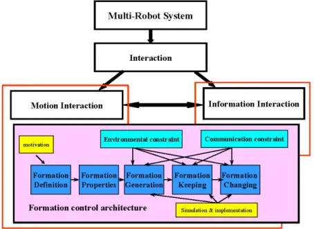
In multi-robot formation control, many issues like formation definition, generation, keeping, changing and the effect of communication and environmental constraint must be taken into consideration. An architecture for multi-robot formation control is required for properly designing every functionality of the multi-robot system. The architecture can be divided into several parts for the purpose of design and analysis. The key architecture under motion and information interactions is shown in Figure 1.
Figure 1 A multi-robot formation control architecture with motion interaction and information constraints (see online version for colours)
First, the formation should be defined by the users. Second, based on the definition, the properties used for formation control can be derived. Note that the interaction among robots highly depends on the properties of formations.
After defining the formations and their properties, a motion controller could be designed for the group behaviour of robots. As the robots follow the design of their motion controllers, they can generate the formation assigned by the user. Furthermore, by appropriately designing control algorithm, e.g., maintaining the robot-to-robot relation, the multi-robot team can keep the formation or change into another formation. Some motion controllers can even affect the properties of one formation or generate a set of different formations. For example, a virtual force generated by the artificial potential field method can be used to drive the motion interaction between robots. The type of motion controllers can make, for example, a three-robot team form a line or a triangle.
In this paper, the motion interaction between robots is designed based on the artificial potential field method which can generate stable formations. Five scenarios of formation control with considering the effect of different information topologies are discussed and analysed in detail. Factors such as robustness, convergence speed, power consumption, and system efficiency are used to compare different information topologies. Therefore, by properly selecting information patterns, the motion interaction of controlling the robot formation can perform more efficiently and robustly.
This paper consists of six sections, including the Introduction section. Section 2 outlines related work and Section 3 formulates the problem studied in the paper and presents the property of generating a formation by a team of robots. Section 4 analyses the motion interaction and information topology of a multi-robot team. In particular, five difference scenarios of generating a multi-robot formation are discussed in detail. Section 5 presents the simulation results and Section 6 concludes the paper and addresses possible future research directions.
2 Related work
In previous works, many researchers used graph theory to represent a formation or model the relationship among robots. In Krishnamurthy and Preis (2005), the authors used basic concepts in graph theory to define a formation, and introduced the graph Laplacian (a representation of vertex-edge relationship) to analyse the linear dynamics of a group of satellites or vehicles. In Olfati-Saber and Murray (2002) and Muhammad and Egerstedt (2004), two special properties: graph rigidity and graph connectivity in graph theory were used to stabilise the dynamics of a multi-vehicle system and model the local interaction of a multi-robot system.
To generate a specific formation by a multi-robot team, many methodologies were developed. In Balch and Arkin (1998), a behaviour-based control law was proposed to regulate the movement of robots. Several basic behaviours were defined and different behaviours were integrated by different weightings. Robots superposing these behaviours then formed formations like column, wedge, and line. Some researchers then developed specific algorithms to let robots form a specific geometric pattern. In Lee et al. (2004), three algorithms named Algorithm L, Algorithm C, and Algorithm P/n were proposed to generate formations of line, circle, and regular polygon with n edges. In Sugihara and Suzuki (1990), distributed algorithms: namely CIRCLE, CONTRACTION, and FILLPOLYGON, were proposed. These algorithms are used to drive robots to form a circle, a line segment, and evenly distributed in a convex polygon. In Fredslund and Mataric (2002), a general algorithm using local sensing and minimal communication was proposed. The robots were assigned unique IDs and a ‘friend’ is defined to represent the relationship between any pair of robots. By the chain of friendships, robots can form formations like column, wedge, line, diamond, and circle.
The leader-follower strategy is also widely used for representing relationship between robots and used for generating formations. In Bicho and Monteiro (2003) and Monteirot et al. (2004), the whole group of robots is decoupled into several pairs of robots. Each pair maintains a leader-follower relationship and each robot can then be a leader or a follower. The follower must track the designated relative velocity and angle from the leader for forming three basic formations: column, oblique, and line. The dynamics of designated relative velocity and angle were modelled as a non-linear system and the equilibrium velocity and angle are designed as attractors. More complex formation like a regular hexagon can be combined by the three basic formations. Detailed mathematic preliminary about non-linear attractor dynamics approach was also proposed in Godenstein et al. (1999). In Das et al. (2002a, 2002b), Fierro et al. (2001) and Tanner et al. (2004), robots identified their neighbour robots and environmental characteristics via the result of processed images. The whole group of robots was also decomposed into
leader and the follower, a basic leader-follower control can be achieved. In Hsu and Liu (2004), the authors used one simple representation combining robot ID and relative angle between robots to define formations. Leader-follower strategy was used in formation generation and keeping. Three agents: namely, user agent, robot agent, and virtual operator, were introduced in the formation control process.
Using virtual structures to control the robot action is an important control law in multi-robot behaviour control. In Tan and Xi (2003) and Tan et al. (2004), based on the relative distance between robots, a Voronoi diagram and its dual graph, Delauney tessellation, can be constructed as a kind of virtual structure. By the structure of Voronoi diagram, robots can cover a certain area and perform search tasks by moving the whole group or forming specific formations. In Popa et al. (2004), Song and Kumar (2002) and Schneider and Wildermuth (2003), a widely used virtual structure: the artificial potential field was used to control the behaviour of robots. This virtual structure is constructed based on the relative distance between robots. Via suitable design, the artificial potential field can generate an artificial force to drive robots and form specific formations. In Ge and Fua (2005), the use of the artificial potential field was extended to generate queues. After robots form several robot queues, formations like wedge, column, arrowhead, and double column can then be generated by combining the robot queues.
Whether the controlling robots is designed according to behavioural based strategy, algorithm design, leader-follower strategy, or virtual structure strategy, the relationship between robots are predefined and fixed and the formation control is then focused on the dynamics of the multi-robot team. In real applications, information sensed by sensors and communicated via networking equipments often faces the issues of information flow, information quantity, network delay, and noise disturbance. With a suitable design of information flow, robots can form formations more efficiently. According to different information flow, robots can form different formations just using the same moving control law and some information flow even make unstable formation (Fax and Murray, 2004; Marshall et al., 2004; Sinha and Ghose, 2005). These works show the importance of controlling the information between robots when forming a specific formation.
In this paper, the formation definition is first presented. Related properties of a formation are then studied. The controlling of one robot is designed based on the artificial potential field. The role of information in multi-robot formation control problem and the impact of on the efficiency of formation generation and keeping are discussed.
3 Problem formulation
3.1 Formation definition
For defining the formation of a multi-robot team, each robot is treated as a vertex and the communication link between any two robots as an edge. Hence, a homogeneous multi-robot team can be described by the two sets: VR and ER, where
VR = {Ri, i = 1, …, n} denotes the robot set and ER ={dR Ri j, ,i …, ,n j=1,…, andn i≠ j} denotes the link set (dR Ri jdenotes the link between robot Ri and robot Rj).
When a formation graph is constructed for the multi-robot team, it also can be viewed as a sensing and/or communicating graph of the multi-robot team. In this study,
bi-way sensing and communication is assumed and the sensing and communication link is always connected. Therefore, the formation graph is an undirected, connected graph.
If two robots are adjacent by a link, it is assumed that they can sense or communicate with each other so that the degree of Ri is defined as the number of the neighbours of Ri,
that is, the total number of robot Ri can sense or communicate. Since the multi-robot team
is homogeneous, the sensing and communication capability of each robot is the same. Therefore, the formation is considered as a regular graph.
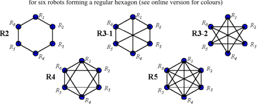
In summary, a regular-degree, undirected, connected, and non-isomorphic formation graph is considered in the study. For example, for a six-robot team, there are five different regular-degree, undirected, connected, and non-isomorphic graphs as shown in Figure 2 (Chartrand and Lesniak, 1997). These graphs are denoted as R2, R3–1, R3–2,
R4, and R5 graphs and R5 is a complete graph.
Figure 2 Five different regular-degree, undirected, connected, and non-isomorphic graphs for six robots forming a regular hexagon (see online version for colours)
Source: Chartrand and Lesniak (1997)
3.2 Information quantity
The information quantity available for the formation controller is greatly affected by the limitation of sensing and communication capability of a robot. On the other hand, with more sensing or communication links, more information about other robots could be obtained. Hence, the information quantity and richness are important factors in formation control and are defined as follows.
Definition 1 (Information quantity qRi and richness rRi): Consider a team of n homogeneous robots, Ri, i = 1, 2, …, n, forming a regular-degree, undirected, connected,
and non-isomorphic formation graph. The information quantity qRi of robot Ri is equal to the number of the neighbouring robots communicating with robot Ri and the information
richness is defined as 100% . 1 i i R R r q n = × −
Hence, for a complete-graph formation, qRi = −n 1 andrRi =100%.. In this case, robot Ri could obtain the information of all the other robots.
For example, the six-robot team shown in Figure 2, each robot in the R2 graph has information quantity qRi = and information richness 2 40%,
i R
r = and each robot in the
complete graph R5 has information quantity qRi = and information richness 5
%.
100 i R
r =
Next, the concept of robustness, convergence speed, power consuming, and system efficiency is introduced for comparing the performance of formation keeping and changing.
Definition 2 (Robustness): Robustness denotes the capability of a formation to gain back
stability when distortion. In this paper, assuming the robot would not break down or fail, so the definition of robustness is used to characterise formation distortion. Hence, when a multi-robot team encounters an obstacle, the maximum deviation of each links is used as a basis to determine the robustness of the regular hexagon with a certain networking topology.
Definition 3 (Convergence Speed): Convergence speed denotes the time consumed
by a robot team from their initial position to the final position of forming a specific formation. The convergence speed can be used to characterise the formation by using different networking topology.
Definition 4 (Power Consumption): For each robot, when the number of sensing or
communicating links increases, the power consumed by sensing or communicating devices also increases. Hence, the power consumption of exchanging information can be characterised by the effort of gaining the data for the other robots and external environment. Note that the power consumption here does not include the power supplied to the motor or engine of the robot itself. Due to the power limitation in each robot, the power consumption must be as small as possible.
Definition 5 (System Efficiency, SE): The system efficiency is defined as follows
(Lee et al., 2004): 1 | ( ) (0) | 1 , ( ) i i i n R R i R X t X SE n = l t − =
∑
(1)where n is the total number of robots in a multi-robot team, |XRi( )t −XRi(0) | is the straight-line distance of a robot from the initial position to the position at time t, and
( ) i R
l t is the total travelling distance of each robot at time t.
Using these factors mentioned above, the regular hexagon formations formed by a multi-robot team with different networking topologies can be compared and related features can be characterised.
4 Interaction analysis of a multi-robot team
4.1 Five scenarios of formation control
In this paper, different scenarios of formation generation are performed by considering the effect of networking topology and the motion interaction between any pair of robots. These scenarios are classified as the following five cases:
1 Trajectory Regulation Procedure (TRP) 2 Dynamical Goal Assignment (DGA) 3 Formation with a Predefined Centre (FPC)
4 Formation with Different Information Quantity (DIQ) 5 Fully Decentralised Control (FDC).
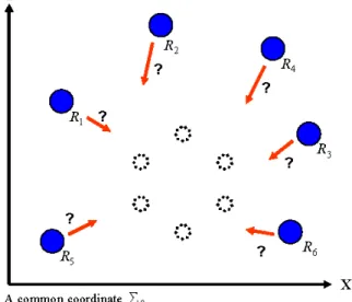
In the TRP case, a specific goal is assigned to every robot. Forming a regular-graph formation is to drive every robot approaching its own goal only. In the DGA case, each robot must first decide its own goal. Hence, in addition to the moving algorithm, a goal competition mechanism should be designed. In the FPC case, these robots are commanded to form a regular-graph formation with a predefined formation centre. In the DIQ case, after these robots form a regular-graph formation, they are commanded to pass through an obstacle to a predefined formation centre with different networking topologies. Finally, in the FDC case, the architecture of FDC for a multi-robot system is proposed. The team of robots can change their own motion controller to plan their motion behaviour. The detailed description and dynamical models of these five scenarios are discussed in the following.
4.2 Dynamical models of formation control 4.2.1 Trajectory Regulation Procedure (TRP)
For ease of presentation, the multi-robot system under consideration has six robots Ri, i = 1, 2, …, 6 assuming that i is a unique ID for each robot and the position vector of
each robot is denoted as [ , ] 2. i
T R i i
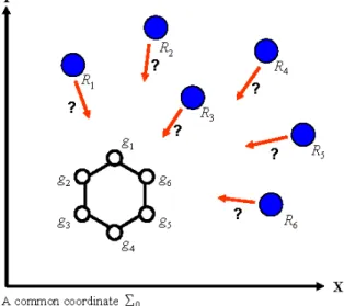
X = x y ∈ R A regular hexagon with six corners locating at Xgi,i=1, 2, ..., 6, can be viewed as six different goals g ii, =1, 2,…, 6. The simplest way to let the six-robot system form a regular hexagon is to uniquely assign robot to individual goal one by one. That is, each robot only sees its own goal and goes to the designated goal location. Therefore, a unique goal for every robot should be pre-assigned separately. The scenario is illustrated in Figure 3.
If one robot has zero information quantity (qRi = 0) and there is no static obstacle,
the dynamical equation of robot Ri can be described as follows:
, , ( ) . ( ) i i i i gi i i i i g R g R a R g R g A X X X d d − − = (2)
Therefore, the equilibrium of the relative distance for the above equation is(dR gi,i =0).
Then, a stable controller for each robot Ri to approach its goal gi could be designed by
properly choosing the constantsA agi, g.
For the complete-graph formation, on the other hand, information from other robots can help robot Ri regulate the trajectory to its goal safely. Then, the dynamical equation
of robot Ri with 100% information richness can be described as follows:
, , ( ) ( ) . ( ) ( ) j i j i i i i gi i i i j i j i i i R R g R g R a r j J R g R R R R R g i R X X A X X X d d d d ∈ − − − − = + −
∑
(3)Therefore, under a suitable design for the constants A agi, gi, R and r, one robot can plan ij a trajectory approaching its goal and dynamically avoiding other robots.
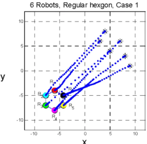
Figure 3 Six robots form a regular hexagon in Case 1 (TRP) (see online version for colours)
Robots form a regular hexagon with a common coordinate. Symbol ‘●’ denotes robots and symbol ‘○’denotes known goals. Each robot goes to a predefined goal location and form a regular hexagon.
Because the relation between the robot and its goal is one by one, this formation control problem can be classified as a kind of trajectory regulation problem. Hence, for a robot, other robots can be viewed as dynamic obstacles. In Figure 3, when one robot approaches to its goal considering moving energy consumption, the best trajectory is a straight line. However, in this scenario, robot collision might happen. When the robot does not see other robots, the information quantity of a robot is zero, and the information richness is poor. Although robots could regulate their trajectories with a smaller energy and time consumption, these trajectories may cause collision among robots and then break the whole system. The robots need a dynamic obstacle avoidance strategy to help them plan trajectory to their goals. Hence, the information quantity plays an important role in the formation control problem. When more information about other robots can be obtained, a safer trajectory to its goal can be planned. Therefore, the best networking topology is the complete graph R5.
4.2.2 Dynamical Goal Assignment (DGA) problem
Consider a more complex situation than that in TRP and assume that each robot can see all the goal location Xgi. The goal, however, is not pre-assigned to any robot in advance. In this case, each robot must decide its own goal location dynamically. In order to save energy, each robot would like to go to the nearest goal from its current location. For this reason, two robots may decide to go to the same goal location during their motion. Hence, certain competition mechanism among these robots should be designed to prevent two or more robots approaching to the same goal. More information quantity can help robots compete with each other and decide where to go. Since the key issue in this case is the competition mechanism, hence, information richness is assumed 100%. Figure 4 illustrates the scenario.
Figure 4 Six robots form a regular hexagon in Case 2 (DGA) (see online version for colours)
Robots form a regular hexagon with a common coordinate. Symbol ‘●’ denotes robots and symbol ‘○’ denotes known goals. Each robot competes with each other to decide which goal to go.
In a centralised control framework, this problem can be viewed as a dynamic goal (target) assignment problem as a special case in generalised assignment problem. Many methodologies such as tabu search, variable depth search, generic algorithm, and combination of greedy method and local search mentioned are developed to solve such problem in a centralised way (Yagiura and Ibaraki, 2004).
In this paper, considering the 100% information richness of each robot, a moving algorithm with a goal competition mechanism is proposed as follows. Using this algorithm, the six-robot team can dynamically decide its own goal and the selected goal would not be the same as those of other robots.
Moving algorithm with a goal competition mechanism
4.2.3 Formation with a Predefined Centre (FPC)
In this case, the final locations of all the robots are assumed to be around a predefined centre C at XC of the regular-graph formation. These robots are also designed to maintain
a fixed distance relative to the formation centre. Hence, the final position of each robot is not predefined. Figure 5 shows the scenario of a six-robot formation. The dynamical equation of robot Ri with 100% information richness about the other robots could be
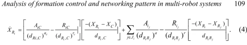
, , , ( ) ( ) ( ) ( ) ( ) ( ) . j j i j i i c c i i i j i j i j i i i R R R C iC iC R a r a r j J R C R R R R R R Ri C R C X X X X A R X d d d d A R d d ∈ − − − − = − + −
∑
(4)With properly choosing the values of AiC, RiC, ac, rc, Aij,Rij,a, and r, the six-robot system can form a regular hexagon around a predefined formation centre.
Figure 5 Six robots form a regular hexagon in Case 3 (FPC) (see online version for colours)
Robots form a regular hexagon around a predefined formation centre. Symbol ‘●’ denotes robots, symbol ‘•’ denotes the predefined formation centre and symbol ‘○’ with dash-line circumference denotes known goals.
To form a regular hexagon, every robot in the multi-robot system must plan its own trajectory according to the formation centre and the relative motion to other robots. The information quantity and the relative networking topology would affect the relative movement between robots and the final location of each corner of the regular hexagon formed by these robots. In this case, if the information richness is not ‘rich’ enough, the collision between robots could happen or the formation may not be a regular hexagon. Hence, for a six-robot team, using the richest information, that is, a complete graph R5, and the dynamical equation (4), the robot collision can be avoided.
4.2.4 Formation with Different Information Quantity (DIQ)
In this case, neither goal location nor formation centre is predefined for each robot. Hence, the trajectory for generating a regular-graph formation depends on the relative movement between the robot and its neighbours. The final location of the regular-graph formation may depend on the initial location of each robot. Information quantity also affects the robustness and convergence speed of forming a regular graph. Figure 6 illustrates the scenario of a six-robot system.
Figure 6 Six robots form a regular hexagon in Case 4 (DIQ) (see online version for colours)
Robots form a regular hexagon. Symbol ‘●’ denotes robots and symbol ‘○’ with dash-line circumference denotes known goals.
The motion controller based on the artificial potential field is designed as follows:
( ) . ( ) ( ) i j i i j i j i j R R ij ij R a r j Ji R R R R R R X X X d A R d d ∈ − − = −
∑
(5)Under different information quantity, the neighbour set Ji of robot Ri is different and the
design of Aij and Rij must be chosen differently with different set of neighbours.
After the six robots form a regular hexagon by using one kind of networking topology, if there is a predefined formation centre C at XC, the whole robot group will
move to the centre. If there is no obstacle on the way to the new centre, the formation can be kept easily by the constraint of artificial force between robots. It is just the scenario of Case 3 (FPC).
Assume that there is an obstacle O at Xo on the way from the initial position to the
formation centre. When the multi-robot team meets the obstacle, the formation will be distorted due to the repulsing force applied by the obstacle to each robot. With different networking topologies, the distortion may be different. Under this scenario, a high-level controller can be designed as follows:
, , , , , , , ( ) ( ) ( ) ( ) ( ) ( ) ( ( ) ( ) ( ) ( ) i i i c c o i i i i i i i j i k i j i j i k i k i j R C R o iC iC io R a r r R C R o R C R C R o j R R R R ij ij ij ik a a r j k m R R R R R R R R R R X X X X A R R X d d d d d X X X X A R A R r d d d d d − − − − = − + − − − − − + − + −
∑
) ( ) + . (6) ( ) ( ) i k i m i m i m i m R R R R ij im a r R R R R R R d X X A R d d d − − − In this case, the trajectory of each robot for forming a regular hexagonal formation depends on the relative movement between each robot and its neighbours. The final position of the corners of the six-robot formation depends on the initial position of each robot. Different types of information quantity can introduce different networking topology and formation graph. Hence, the artificial force acting on each robot is also different. Moreover, information quantity also affects the robustness and the convergence speed of forming a formation.
4.2.5 Fully Decentralised Control (FDC)
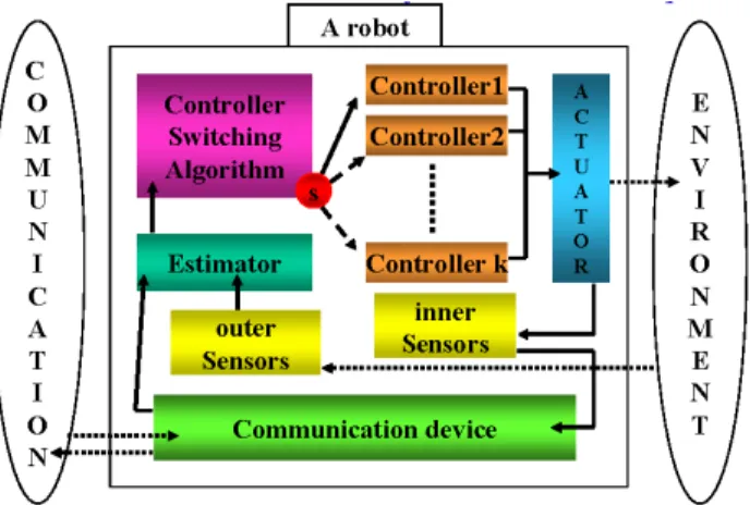
For the cases discussed previously, a unique robot ID and a set of predefined neighbouring robots for each robot are assumed. In order to perform FDC, these assumptions should be dropped. Since the neighbours of each robot are not pre-assigned, the robot must first decide its own neighbour set within the sensing or communication range. Once all the robots have constructed their neighbour sets, they can generate associated networking topology based on the information obtained. Consider a team of six homogeneous robots as shown in Figure 7. With no unique robot ID, no goal location, and no predefined formation centre, the key issue here is to make these robots form a regular hexagon by following a simple command such as ‘form a regular hexagon’. The fully decentralised controller architecture for a multi-robot team is proposed as shown in Figure 8.
In the architecture shown in Figure 8, each robot in a multi-robot team obtains information from its own sensors and/or by communicating with other robots. The inner sensors can provide information about the state of the physical part of the robot. The robot can then estimate the location in a common coordinate. The outer sensors provide information about the status of other robots within the sensing range. The information can be used to estimate the relative distance between the robot and other robots. Communication devices equipped on the robot broadcast the position data measured by the inner sensors, and also receive similar information broadcast by other robots within the communication range. The information shared by communication can help compensate the error of the relative distance between robots calculated only from sensor reading.
Figure 7 Six robots form a regular hexagon in Case 5 (FDC) (see online version for colours)
Symbol ‘●’ denotes robots and symbol ‘○’ with dash-line circumference denotes known goals. It is the case of Fully Decentralised Control in multi-robot formation
Figure 8 Controller switching architecture of a Fully Decentralised Controlled robot. A robot can choose a controller within its controller set for responding the working environment and interact with other robots (see online version for colours)
Because the neighbours of each robot are not pre-assigned, the robot must decide the set of neighbour robots within the sensing or communication range. The robot also creates a set of self-defined robot IDs to its neighbour robots. Once all the robots have decided their neighbour sets, they must estimate the networking topology according the information gathered.
Based on the estimated networking topology, a controller switching algorithm should decide a proper controller from a pre-defined controller set for planning a trajectory to react to the neighbour robots. After the control law is selected, the controller switching algorithm then chooses a suitable control gain for the controller. The reaction can be viewed as the response to the changes in the environment and the robot team. Again, the change is obtained by the outer sensors and the new information from communication device. The control architecture is fully decentralised because each robot can independently decide the set of neighbour robots to react and the controller to be used.
Fully Decentralised Control is hard to realise due to the design complexity of the estimator for deciding neighbour-robot set and estimating networking topology. In Cases 1–4 mentioned above, the robots marked by a unique ID can help a robot to pre-define the set of neighbour robots. Therefore, the design complexity for trajectory planning can be reduced.
When a multi-robot team operates in an environment with obstacles, related factors such as robustness, power consumption, convergence speed, collision detection, and system efficiency can be used as a basis of selecting different networking topology as well as controller for keeping a specific formation.
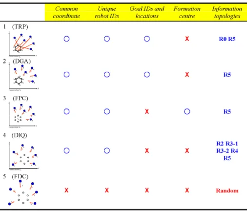
In this section, five scenarios considering information quantity as a kind of communication constraint for forming a regular hexagon formation of a multi-robot team are discussed. Characteristics of the five scenarios are summarised in Table 1. The high-level controller for each scenario is designed. A simple controller switching algorithm is proposed for the scenario of FDC. In next section, software simulations of the five scenarios are extensively studied.
Table 1 Characteristics of the five cases (see online version for colours)
○: with; ×: without.
TRP: Trajectory Regulation Problem. DGA: Dynamic Goal Assignment. FPC: Formation with a Predefined Centre.
DIQ: Formation with Different Information Quantity. FDC: Fully Decentralised Control.
5 Simulation study
In this section, the simulation study of the five scenarios is presented. The dynamical model of each robot and the motion controller are constructed in the scientific programming environment: MATLAB. The whole set of dynamical equations are solved by the MATLAB numerical integration function. The simulation results illustrate the robot behaviours in the five scenarios studied and provide guidelines for parameter selection in the design of the artificial potential fields.
5.1 Trajectory Regulation Procedure (TRP)
First, consider the case that no communication exists between any pair of robots or no sensing data are available. In the case, any robot does not know the location of other
goal. Use equation (2) and let Agm =5 andag =0.2. Figure 9 shows the simulation of the movement of each robot in a two-dimensional space. In Figure 9, symbol ‘*’ denotes the initial position of these robots, ‘○’ denotes the goal location, ‘•’ denotes the robot moving trajectory, and ‘●’ denotes the final position of these robots.
Figure 9 Six robots are commanded to their own goals with no information quantity. Since there is no communication, each robot only plans a straight line trajectory to achieve its goal (see online version for colours)
Second, the interaction between any pair of robots is considered, that is, collision avoidance mechanism is included. Use equation (3) and the following additional parameters are also used in the simulation: Rij = 1 and r = 4. The other parameters
are the same as in the first scenario. Figure 10 shows the trajectory of these six robots. In Figure 9, the controller only commands each robot to go to its goal directly. Hence, the trajectory of each robot is just a straight line. With no information about other robots, one robot may collide with other robots. In Figure 10, by introducing the repulsive force from other robots, each robot can avoid them as dynamic obstacles while moving to the goal. For example, the trajectories of R1 and R2 are not just straight lines.
Figure 10 Six robots are commanded go to their own goals with dynamic obstacle avoidance (see online version for colours)
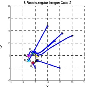
5.2 Dynamical Goal Assignment (DGA)
In this case, these robots are then controlled by using the moving algorithm with a goal competition mechanism. Figure 11 shows the simulated trajectories of the six robots. Since the initial position of R1 and R6 are close to the goal location: g4 and g5, they always
win the competition and go to g4 and g5, respectively. Other robots: R2, R3, R4, and R5
then compete with others for going to the nearest goal. Finally R2 approaches to g3, R3
approaches to g1, R4 approaches to g2, and R5 approaches to g6. This simulation illustrates
that, under suitable design of the competition mechanism among robots, and using 100% information quantity for each robot, they can properly approach to their own goals successfully.
Figure 11 The moving trajectory of these robots. The trajectory oscillation of some robots, e.g., R4, is caused by the goal competing mechanism in the moving
algorithm (see online version for colours)
5.3 Formation with a Predefined Centre (FPC)
Figure 12 shows the simulation result of generating a formation with a predefined centre. For easy of presentation, only the trajectories of R1, R3 and R6 are shown and
other trajectories are omitted. As shown in Figure 12, the final position around the formation centre of each robot highly depends on both the initial position of each robot and the artificial force from the formation centre and other robots. Hence, it can be seen that the information quantity also effect the relative movement among these robots.
Figure 12 Trajectories of six robots forming a regular hexagon around a predefined centre (see online version for colours)
5.4 Formation with Different Information Quantity (DIQ) 5.4.1 Simulation result of different information topologies
In this subsection, the simulation of six robots forming a regular hexagon using the five networking topologies, R2, R3–1, R3–2, R4, and R5, are studied. Use equation (5) and let Aij = 3, a = 0.5, Rij = 20.4⋅ 3, Rik = 40.4⋅ 3 and
( )
0.4 2 3 3, im
R = ⋅ and r = 0.9, where j, k, m, denote the neighbour robots. For different networking topologies, Rij, Rik, Rim are
set to zero for those un-exist links. Figure 13 shows the trajectories of the six robots forming a regular hexagon using one of the following networking topologies. The definition of the symbols used in these figure are the same as those used previously. In all the five networking topologies, the six-robot team can form a regular hexagon and all the links between any pair of robots converge to their desired values, that is,
2units, 4 units and 2 3 units.
i j i k i m
R R R R R R
d = d = d =
Figure 13 Trajectory of six robots forming a regular hexagon formation: (a) R2 topology; (b) R3–1 topology; (c) 10 R3–2 topology; (d) 1 R4 topology and (e) R5 topology (see online version for colours)
Figure 13 Trajectory of six robots forming a regular hexagon formation: (a) R2 topology; (b) R3–1 topology; (c) 10 R3–2 topology; (d) 1 R4 topology and (e) R5 topology (see online version for colours) (continued)
(c) (d)
(e) Because R2 is not a rigid graph, the formation flexing may happen. Hence, for some initial conditions, R2 can let robots form a regular hexagon. Using the other four topologies, a regular hexagon can be formed successfully. Table 2 shows the convergence speed of the four networking topologies that can form a regular hexagon. The results suggests that using R3–1 and R5 networking topologies, the six robot system can form a regular hexagon faster than using R3–2 and R4 networking topologies. Using R3–2 networking topology for a six-robot team to form a regular hexagon spends the longest time to converge to the regular hexagon. One reasonable explanation is that one robot gives up the nearest two robots to be its neighbours but treats the farthest three robots as its neighbours. That makes the relative movement between the two non-neighbour robots
will take a longer time to form a regular hexagon. Table 3 shows the power consumption of the four networking topologies that can keep the regular hexagon. The R3–1 and R3–2 networking topologies consume the least communication power.
Table 2 Convergence speed of the four networking topologies. R3–1 and R5 networking topologies make the six-robot system form a regular hexagon faster than R3–2 and R4 networking topologies
R3–1 R3–2 R4 R5
Convergence speed (s) 18.5 53.5 24.7 12.8
Good topology V V
Table 3 Power consumption of each networking topology. R3–1 and R3–2 networking topologies have less power consumption then the other two
R3–1 R3–2 R4 R5
Info. quantity 60% 60% 80% 100%
Good topology V V
5.4.2 Simulation result of formation keeping
In this subsection, six robots forming a regular hexagon using the five networking topologies: R2, R3–1, R3–2, R4 and R5, are driven to a predefined formation centre C by passing through an obstacle O. Use equation (6) and the following parameters are used in the motion controller: AiC = 5, RiC = 9, ac = 1.1111, rc = 2, Ro = 10, ro = 10, Aij = 3,
a = 0.5, Rij = 20.4⋅ 3, Rik = 40.4⋅ 3 and
( )
0.42 3 3
im
R = ⋅ and r = 0.9. For different
networking topologies, Rij, Rik, Rim are set as zero for those un-exist information links.
The predefined formation centre is located at XC = [3, 3]T, and the obstacle is located at
XO = [8, 8]T. Figure 14 shows the trajectories of the six robots. The definition of the
symbols used in these figure are the same as those used previously. In additions, ‘☆’ and ‘■’ denote the predefined formation centre and the obstacle, respectively. When passing through the obstacle, a snap shot of the formation is also shown.
The simulation results shown in Figure 14 suggest that using R3–1, R3–2, R4, and
R5, the formation can be kept when the environmental uncertainty is presented, but using R2 the formation might turn into another isomorphic graph. Since R2 is not a rigid graph
(its link number is less than 2 × 6 – 3 = 9), so it can be easily disturbed by uncertainty. The maximum deviation percentage of the positions of any two robots is smallest when the networking topology is R3–1. That is, among the four networking topologies, the R3–1 networking topology is the most robust topology. Hence, using R3–1 would be the relatively ideal networking topology for a six-robot team to form a regular hexagon with no obstacles. On the other hand, because of its robustness, using R5 would be the relatively ideal networking topology for a six-robot team when crossing obstacles.
In summary, R3–1 would be the ideal networking topology for a six-robot team to form a regular hexagon with no obstacles and R5 would be the ideal networking topologies for a six-robot team when passing obstacles. With this result, R3–1 and R5 will be used in the scenario of Case 5 (FDC) studied in next subsection.
Figure 14 Trajectory of six robots forming a regular hexagon formation and passing through an obstacle. (a) R2 topology; (b) R3-1 topology; (c) R3-2 topology; (d) R4 topology and (e) R5 topology (see online version for colours)
(a) (b)
5.5 Case 5: Fully Decentralised Control (FDC)
In this scenario, six robots forming a regular hexagon using the two networking topologies, R3–1 and R5, passing through an obstacle O to a predefined formation centre C are studied. Use equation (6) and the following parameters are used in the motion controller: AiC = 5, RiC = 9, ac = 1.1111, rc = 2, Ro = 10, ro = 10, Aij = 3,
a = 0.5, Rij = 20.4× 3, Rik = 40.4× 3 and
( )
0.42 3 3
im
R = × and r = 0.9. For different
networking topologies,
R
ij,R
ik,R
im are set to zero for those un-exist information links. Figures 15 and 16 show the trajectory of the six robots and the snapshot of the simulation for the case of the obstacles are at Xo = [6, 8]T and Xo = [8, 8]T, respectively. For savingcommunication power, the six-robot team first forms a regular hexagon by using the ideal networking topology R3–1. When the robot team encounters an obstacle, these robots change the networking topology into R5 for coordinating its neighbours to pass through the obstacle. After the six-robot team passes through the obstacle, the networking topology then changes back to R3–1.
Figure 15 Trajectory of the six robots and snapshot of the simulated formations. The six-robot team changes its networking topology from R3–1 graph to R5 graph when
encountering an obstacle at Xo = [6, 8]T (see online version for colours)
As shown in Figures 15 and 16, the six-robot team first forms a regular hexagon formation using the relatively ideal networking topology R3–1. When the robot team passes through an obstacle, each robot switches the high-level controller based on the networking topology R5 to react to its neighbours. After the six-robot team passed the obstacle, the networking topology then turns back to R3–1 for saving communication power. For the case of the obstacle O located at Xo = [6, 8]T, the whole robot team winds
around the obstacle. For the case of the obstacle O located at Xo = [8, 8]T, the whole robot
team crosses the obstacle.
The system efficiency of these simulated cases is summarised in Table 4. The system efficiencies are higher by using the controller switching algorithm than by using R2,
Figure 16 Trajectory of the six robots and snapshot of the simulated formations. The six-robot team changes its networking topology from R3–1 graph to R5 graph when
encountering an obstacle at Xo = [8, 8]T (see online version for colours)
Table 4 Comparison result of the system efficiency
R2 R3–1 R3–2 R4 R5 CP (8,8)
Efficiency 90.27% 92.93% 91.93% 92.28% 92.03% 93.20%
6 Conclusions and future work
In this study, six robots are teamed as a regular hexagon with different information sharing patterns and then commanded to pass through an obstacle to a predefined formation centre. Key issues discussed including trajectory regulation problem, dynamic goal assignment, forming a regular hexagon around a predefined formation centre, forming a regular hexagon with different networking topologies, and a simple controller switching algorithm are analysed in detail. The analysis shows that the motion interaction and information interaction affect each other when a multi-robot team forms a specific formation pattern. Controller design for robots should consider both motion interaction and information interaction and then make robots cooperate efficiently. Simulation results show that the R2 pattern is not a suitable networking topology of forming a regular hexagon. Because the R2 networking pattern is not a rigid graph, the regular hexagon is easily distorted by environmental changes. The R3–1 networking pattern is a relatively ideal topology to form a regular hexagon because it has a fast convergence speed, less power consuming and good robustness. The R5 pattern is the relatively ideal networking topology for obstacle avoidance because it is the most robust networking topology among these five graphs and it can detect obstacles or robot collision easily.
Future research work includes the characterisation of the information quality such as resolution of sensing readings and communication data, information transmission delay, and disturbance of noise. And more complex scenarios such as more obstacles and transporting a regular-polygon-shape object can be considered in the simulation
scenarios. FDC methodology should be developed so that the behaviour of these robots are more like natural creatures and a multi-robot team can has scalable characteristics.
Acknowledgement
This research was supported in part by the National Science Council, Taiwan, ROC, under the grants: NSC 95-2218-E-002-303-MY3 and NSC 96-2218-E-002-030, and DOIT/TDPA: 95-EC-17-A-04-S1-054.
References
Balch, T. and Arkin, R.C. (1998) ‘Behavior-based formation control for multirobot teams’, IEEE Transaction on Robotics and Automation, Vol. 14, No. 6, December, pp.926–939. Bicho, E. and Monteiro, S., (2003) ‘Formation control for multiple mobile robots: a non-linear
attractor dynamics approach’, Proceedings of the IEEE/RSJ Intl. Conference on Intelligent Robots and Systems, Las Vegas, Nevada, USA, October, pp.2016–2022.
Chartrand, G. and Lesniak, L. (1997) Graphs and Digraphs, 3rd ed., Chapman & Hall/CRC, Boca Raton, Florida, USA.
Das, A.K., Fierro, R., Kumar, V., Ostrowski, J.P., Spletzer, J. and Taylor, C.J. (2002a) ‘A vision based formation control framework’, IEEE Transactions on Robotics and Automation, Vol. 18, No. 5, October, pp.813–825.
Das, A., Spletzer, J., Kumar, V. and Taylor, C. (2002b) ‘Ad Hoc networks for localization and control’, Proceedings of the IEEE International Conference on Decision and Control, Las Vegas, Nevada USA, December, pp.2978–2983.
Fax, A. and Murray, R.M. (2004) ‘Inforamtion flow and cooperative control of vehicle formation’, IEEE Transactions on Automatic Control, Vol. 49, No. 9, September, pp.1465–1476.
Fierro, R., Das, A.K., Kumar, V. and Ostrowski, J.P. (2001) ‘Hybrid control of formations of robots’, Proceedings of the IEEE International Conference on Robotics and Automation, Seoul Korea, May, pp.157–162.
Fredslund, J. and Mataric, M.J. (2002) ‘A general algorithm for robot formations using local sensing and minimal communication’, IEEE Transaction on Robotics and Automation, Vol. 18, No. 5, October, pp.837–846.
Ge, S.S. and Fua, C-H. (2005) ‘Queues and artificial potential trenches for multi-robot formations’, IEEE Transactions on Robotics, Vol. 21, No. 4, August, pp.646–656.
Godenstein, S., Large, E. and Metaxas D. (1999) ‘Non-linear dynamical system approach to behavior modeling’, The Visual Computer, pp.349–364.
Hsu, H.C-H. and Liu, A. (2004) ‘Multiple teams for mobile robot formation control’, Proceedings of the IEEE International Symposium on Intelligent Control, Taipei Taiwan, September, pp.168–173.
Krishnamurthy, A. and Preis, R. (2005) ‘Satellite formation, a mobile sensor network in space’, Proceedings of the IEEE International Symposium on Parallel and Distributed Processing, Denver, Colorado USA, April, pp.243–249.
Lee, J., Venkatesh, S. and Kumar, M. (2004) ‘Formation of a geometric pattern with a mobile wireless sensor network’, Journal of Robotic System, Vol. 21, No. 10, March, pp.517–530. Leonard, N.E. and Fiorelli, E. (2001) ‘Virtual leaders, artificial potentials and coordinated control
of groups’, Proceedings of the 40th IEEE Conference on Decision and Control, Vol. 3, December, pp.2968–2973.
Marshall, J.A., Broucke, M.E. and Francis, B.A. (2004) ‘Formations of vehicles in cyclic pursuit’, IEEE Transactions on Automatic Control, Vol. 49, No. 11, November, pp.1963–1974. Monteirot, S., Vaz, M. and Bicho, E. (2004) ‘Attractor dynamics generates robot formations: from
theory to implementation’, Proceedings of the IEEE International Conference on Robotics and Automations, New Orleans, LA, USA, April, pp.2582–2587.
Muhammad, A. and Egerstedt, M. (2004) ‘Connectivity graphs as models of local interactions’, Proceedings of the IEEE Conference on Decision and Control, Atlantis Paradise Island Bahamas, December, pp.124–129.
Murphy, B.R. (2000) Introduction to AI Robotics, The MIT Press, Cambridge, Massachusetts, USA.
Olfati-Saber, R. and Murray, R.M. (2002) ‘Graph rigidity and distributed formation stabilization of multi-vehicle system’, Proceedings of the IEEE International Conference on Decision and Control, Las Vegas Nevada USA, December, pp.2965–2971.
Popa, D.O., Helm, C., Stephanou, H.E. and Sanderson, A.E. (2004) ‘Robotic deployment of sensor networks using potential fields’, Proceedings of the IEEE International Conference on Robotics and Automations, New Orleans, LA, USA, April, pp.642–647.
Schneider, F.E. and Wildermuth, D. (2003) ‘A potentail field based approach to multi-robot formation navigation’, Proceedings of the IEEE International Conference on Robotics, Intelligent System and Signal Processing, Changsha, China. October, pp.680–685.
Sinha A. and Ghose, D. (2005) ‘Generalization of the cyclic pursuit problem’, Proceedings of American Control Conference, Portland, OR, USA, June, pp.4997–5002.
Song, P. and Kumar, V. (2002) ‘A potential field based approach to multi-robot manipulation’, Proceedings of the IEEE International Conference on Robotics and Automation, Washington DC, USA, May, pp.646–656.
Sugihara, K. and Suzuki, I. (1990) ‘Distributed motion coordination of multiple mobile robots’, Proceedings of the IEEE International Symposium on Intelligent Control, Vol. 1, September, pp.138–143.
Tan, J. and Xi, N. (2003) ‘Integration of sensing, computation, communication and cooperation for distributed mobile sensor networks’, Proceedings of the IEEE International Conference on Robotics, Intelligent Systems and Signal, China, October, pp.54–59.
Tan, J., Xi, N., Sheng, W. and Xiao, J. (2004) ‘Modeling multiple robot systems for area coverage and cooperation’, Proceedings of the IEEE International Conference on Robotics and Automations, LA, USA, Vol. 3, April, pp.2568–2573.
Tanner, H.G., Pappas, G.J. and Kumar, V. (2004) ‘Leader-to-formation stability’, IEEE Transaction on Robotics and Automation, Vol. 20, No. 3, June, pp.443–455.
Yagiura, M. and Ibaraki, T. (2004) ‘Recent metaheuristic algorithms for generalized assignment problem’, Proceedings of IEEE International Conference on Informatics Research for Development of Knowledge Society Infrastructure, Kyoto, Japan, March, pp.229–237.