國立交通大學
機械工程學系
博 士 論 文
渦卷壓縮機軸向順從機構設計與應用之研究
Research on Design and Applications of Axial-compliance
Mechanism for Scroll-type Compressors
研 究 生:湯岳儒
指導教授:洪景華 教授
II
渦卷壓縮機軸向順從機構設計與應用之研究
Research on Design and Applications of Axial-compliance
Mechanism for Scroll-type Compressors
研 究 生:湯岳儒 Student:Yuehju Tang
指導教授:洪景華 Advisor:Chinghua Hung
國 立 交 通 大 學
機 械 工 程 學 系
博 士 論 文
A DissertationSubmitted to Department of Mechanical Engineering College of Engineering
National Chiao Tung University in partial Fulfillment of the Requirements
for the Degree of Doctor of Philosophy
In
Mechanical Engineering
January 2013
Hsinchu, Taiwan, Republic of China
III
渦卷壓縮機軸向順從機構設計與應用之研究
研究生:湯岳儒 指導教授:洪景華 教授 國立交通大學機械工程學系博士班
摘 要
對於講究節能環保的現代化高效率變頻冷凍空調系統而言,搭載直流無刷變頻馬達之 變頻渦卷式壓縮機已成為技術發展之主流。而欲克服渦卷壓縮機因應變頻容量調節伴隨而 來的容積壓縮效率變化問題,首要解決之關鍵便是變頻壓縮泵的內部洩漏問題。本研究所 探討之渦卷壓縮機軸向順從機構,由作用於固定渦卷背部的背壓機構與提供渦卷間隙控制 的懸吊機構所組成。此順從機構可動態調整渦卷間隙使維持於一固定最佳值,以減少當負 載變動時因渦卷壓縮腔室間的內部洩漏所造成的容積壓縮效率變化,使渦卷壓縮機得以在 負載變動時可持續維持高容積效率。 用於實現高性能變頻低壓外殼型渦卷壓縮機的幾個軸向順從機構的關鍵技術已在本 研究中完成開發與調查。首先進行軸向洩漏路徑幾何數學模型建構與數值模擬分析研究, 隨後實際開發一軸向順從機構,並裝置於一低壓外殼 R22 冷媒空調變頻渦卷壓縮機雛型進 行性能測試。實驗結果證實,藉由適當的順從機構設計,在各種轉速操作條件,皆可維持 雛型壓縮機的高容積效率。而實測結果亦發現,軸向順從機構的作用能擴展空調用渦卷壓 縮機可變轉速操作範圍至更高及更低轉速,並提升效率 4.7%~13.5%。此外,由實測觀察發 現,此軸向順從機構尚可減輕低壓外殻型壓縮機泵體機件運轉碰撞之噪音問題。 最後,為驗證所研究的軸向順從機構設計原理可廣泛適用於不同種冷媒之應用,實際IV
進行了 R410A 及 R744(CO2)冷媒低壓外殼型渦卷壓縮機雛型開發案例研究,其中導入有限
元素法協助進行軸向順從機構設計變更。實驗證實,本研究之軸向順從機構可成功應用於 不同種冷媒之壓縮機應用。
V
Research on Design and Applications of Axial-compliance
Mechanism for Scroll-type Compressors
Student:Yuehju Tang Advisor:Dr. Chinghua Hung
Department of Mechanical Engineering
National Chiao Tung University
ABSTRACT
A variable-speed scroll-type compressor (STC) with brushless DC convertor motor has become the mainstream of the technological development because of the requirements for energy-saving and environmental protection in modern high-efficiency inverter refrigeration and air conditioning systems. To overcome the problem of the volume compression efficiency change by the inverter capacity adjusting, the primary key to the solution is to solve the internal leakage problem of the variable-speed compression pump.
In this study, the axial-compliance mechanism (ACM), which is composed of a backpressure regulating mechanism acting on the fixed scroll back and a suspension mechanism controlling the scroll clearance, was studied. The use of the ACM enables dynamical adjustments, which allow the scroll clearance to be maintained at a fixed optimal value in order to reduce the varying of volume compression efficiency by the internal leakage in the scroll compression chambers and the high volumetric efficiency can thus be maintained while the system load changed.
Several critical techniques for accomplishing a high-performance, variable-speed low-pressure-side (LPS) STC with an ACM have been developed and investigated. First, the
VI
mathematical model of axial leakage value was constructed, and the advantages of this model were confirmed by numerical simulations and experimental validations with the developed ACM in an R22 LPS STC prototype. The experimental results showed that if the compliance mechanism is designed appropriately, the compressor can achieve a high volumetric efficiency, irrespective of the operating speed conditions. Because of the ACM, the speed range of the variable-speed scroll compressor can be extended and the efficiency can be improved by 4.7–13.5%. In addition, from the experimental observations, a fact was discovered that the ACM can also reduce the noise between the colliding components of the LPS STC.
Finally, for the understanding and verification of the proposed ACM design method could be extended its application to different refrigerant STCs. Case studies of a R410A and a R744 (CO2) applications in the LPS STC prototypes was formulated in this study. Furthermore, the
application of the finite element method was introduced for the ACM mechanism design changes. From the experiment results, the proposed ACM design methods can successfully applications in these different refrigerant STCs.
Keywords: Inverter air conditioner, Scroll type compressor, Leakage, Axial-compliance mechanism, axial clearance
VII
誌 謝
感謝洪錫源老師引領學生進入創造知識的研究行列,在博班求學的前三年鼓勵學生將 職場與學校的工作鏈結起來,激發學生對研究的興趣與對探索未知的熱忱,在您指導期 間,學生著實受益良多。學生在此更要由衷感謝指導教授洪景華老師,願意不辭辛勞地延 續指導學生的博士研究工作,在研究過程中適時給予學生信心與鼓勵,除幫助學生建立專 業領域的學養與知識外,更引領學生培養獨立研究的精神與嚴謹的邏輯思維,讓學生得以 順利完成博士論文,邁向新的階段。 非常感謝口試委員,宋震國教授、陳俊勳教授、馮展華教授、張鈺炯博士和陳伸岳博 士,感謝您們在百忙中仍願意撥空冒著寒風細雨來參加學生的學位口試,感謝您們提出諸 多寶貴的建議與指導,讓學生的論文可以更加完整。 求學期間特別要感謝能源局經費支持,使學生能順利進行各項研究工作,感謝工研院 的長官與同事們的諸多照顧與提攜,也要感謝實驗室學長與學弟妹們多年的幫助與關懷。 細數在交大歷經八個寒暑的學生生涯,有辛勞也有歡樂,求學階段雖將告一段落,然 而更漫長的人生學習才正要開始。雖然,這一路帶職求學的旅程,辛苦多於快樂,尤其是 面臨工作的轉換、生活的壓力以及指導教授的變更,種種無形的壓力讓我常常陷入低潮, 甚至一度想放棄學業,在此要感謝我的家人們在精神上給予無限的支持與鼓勵,在這段期 間,親情是我最大的精神支柱。 最後,謹以此論文獻給我最敬愛上帝、我的雙親與我的愛妻。VIII
TABLE OF CONTENTS
摘 要 ... III ABSTRACT ... V 誌 謝 ... VII TABLE OF CONTENTS ... VIII LIST OF TABLES ... XI LIST OF FIGURES ... XII NOMENCLATURE ... XIV
CHAPTER 1 INTRODUCTION ... 1
1.1 Background ... 1
1.2 Motivation and objectives ... 2
1.3 Axial-compliance sealing methods ... 3
1.4 Variable-speed STC ... 5
1.5 Different sealing in low-side and high-side STCs ... 6
1.6 Structure of dissertation ... 7
CHAPTER 2 STUDY ON LEAKAGE EFFECT IN LOW-PRESSURE-SIDE STC ... 13
2.1 Literature review ... 13
2.2 Numerical simulations of inner leakage effect ... 14
2.3 Mathematical model of radial leakage ... 14
2.4 Case study on theoretical performance simulations ... 18
2.5 Remarks ... 20
CHAPTER 3 AXIAL-COMPLIANCE MECHANISM OF LPS STC ... 31
3.1 Backpressure mechanism design ... 31
3.2 Suspension ACM design ... 33
3.3 Study on structural design and analysis of new leaf-spring-type ACM ... 34
3.3.1 Literature review ... 35
3.3.2 Basic analysis of inner force for the ACM design ... 36
3.3.3 CAE simulation model for improving ACM design ... 39
3.3.4 Prototype experimental results ... 39
3.3.5 Discussion on development of leaf-spring ACM ... 40
IX
3.4 Study of novel compliant suspension mechanism in LPS STC ... 41
3.4.1 Background ... 42
3.4.2 Basic analysis ... 43
3.4.3 Prototype ... 45
3.4.4 Experiment ... 45
3.4.5 Results and discussion ... 46
3.5 Remarks ... 47
CHAPTER 4 STUDY ON R22 STC DEVELOPMENT AS A DESIGN BASELINE ... 62
4.1 Suspension ACM Model of R22 STC ... 62
4.2 Simulation and experiment ... 63
4.2.1 Results of variable-speed tests ... 63
4.2.2 Discussion of development of ACM for R22 STC ... 64
4.3 Remarks on development of ACM for R22 STC ... 65
CHAPTER 5 CASE STUDIES OF ACM APPLICATIONS ... 69
5.1 Comparative study on characteristics of alternative refrigerants ... 69
5.1.1Performance investigation of refrigerants as alternatives to R22 ... 69
5.1.2 Literature review of leakage of CO2 gas with oil mixture in STC ... 72
5.1.3 Numerical simulations of inner leakage effect on alternative refrigerants ... 75
5.1.4 Remarks on the investigation of alternative refrigerants ... 75
5.2 Basic ACM design configuration for case studies ... 76
5.2.1 Design configuration of backpressure pin mechanism ... 76
5.2.2 Design configuration of suspension mechanism ... 77
5.3 Case studies for different refrigerant applications ... 78
5.3.1 Case study of design for R410A STC ... 78
5.3.2 Case study of design for R744 (CO2) STC ... 79
5.4 Remarks ... 80
CHAPTER 6 CONCLUSIONS AND FUTURE WORK ... 97
6.1 Conclusions ... 97
6.2 Scope for the future work ... 100
REFERENCES ... 101
APPENDIX A-Patent research of axial-compliant sealing ... 106
APPENDIX B-Mathematical model of sealing path ... 109
X
APPENDIX D-Technical specifications of CO2 compressor test rig ... 130 AUTHOR’S PUBLICATION LIST ... 136 VITA ... 138
XI
LIST OF TABLES
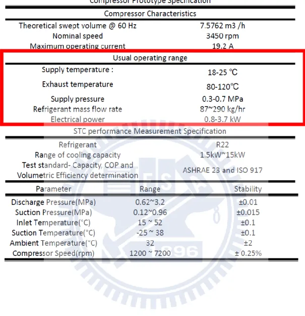
TABLE 2-1STC PARAMETERS AND EXPERIMENTAL OPERATING CONDITIONS ... 27
TABLE 2-2COMPRESSOR PROTOTYPE AND STC PERFORMANCE MEASUREMENT SPECIFICATIONS .. 28
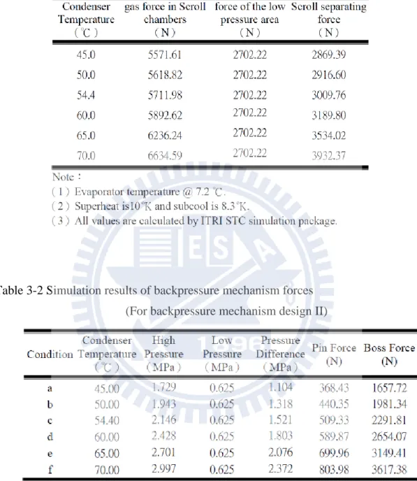
TABLE 3-1SEPARATE FORCES OF FIXED SCROLL AT VARIABLE COMPRESSOR OPERATING CONDITIONS ... 52
TABLE 3-2SIMULATION RESULTS OF BACKPRESSURE MECHANISM FORCES ... 52
TABLE 3-3OPERATING CONDITIONS OF MODEL I COMPRESSOR ... 56
TABLE 3-4TEST RESULTS OF LEAF SPRING OF MODEL I ... 56
TABLE 3-5TEST RESULTS OF MODEL I COMPRESSORS ... 56
TABLE 3-6TEST RESULTS OF NOISE OF MODEL I ... 57
TABLE 3-7TEST RESULTS ... 61
TABLE 5-1REFRIGERANT COMPARISON ... 81
TABLE 5-2PARAMETER LIST OF CO2 COMPRESSOR [51] ... 84
TABLE 5-3BOUNDARY CONDITIONS FOR CAE SIMULATIONS (I) ... 86
TABLE 5-4BOUNDARY CONDITIONS FOR CAE SIMULATIONS (II) ... 87
TABLE 5-5R410ASTC PARAMETERS AND EXPERIMENTAL OPERATING CONDITIONS ... 89
TABLE 5-6TEST RESULTS OF R410A PROTOTYPES ... 92
XII
LIST OF FIGURES
FIG.1.1LOW(-PRESSURE)-SIDE SCROLL-TYPE COMPRESSOR (LPSSTC) ... 8
FIG.1.2COMPLETE CYCLE OF STC COMPRESSION PROCESS ... 9
FIG.1.3TIP SEALING MEANS:ARTHUR D.LITTLE,INC.,US3,994,636,NOV.30,1976 ... 10
FIG.1.4PRESSURIZED GAS TO BACK OF ORBITING SCROLL……….10
FIG.1.5PRESSURIZED GAS TO BACK OF FIXED SCROLL ... 10
FIG.1.6PRESSING MEMBER:TECUMSEH CO. ... 10
FIG.1.7FLUID PRESSURE AS BACKPRESSURE ON SCROLL MEMBER ... 11
FIG.1.8HIGH-SIDE AND-LOW SIDE SHELL CONFIGURATIONS OF STC ... 12
FIG.2.1INNER LEAKAGE TYPE ... 21
FIG.2.2INVOLUTE LEAKAGE PATH ... 22
FIG.2.3INTEGRATED AND SIMPLIFIED LEAKAGE PATH MODEL (AS CIRCULAR PATH) ... 23
FIG.2.4LEAKAGE FLOW SIMULATION MODEL ... 24
FIG.2.5CONCENTRIC CIRCLES AS LEAKAGE PATH ... 25
FIG.2.6ALGORITHM FOR CALCULATING LEAKAGE ... 26
FIG.2.7CALCULATION RESULTS:COP VALUE VERSUS LEAKAGE CLEARANCE ... 29
FIG.2.8CALCULATION RESULTS:VOLUMETRIC EFFICIENCY VERSUS LEAKAGE CLEARANCE ... 29
FIG.2.9CALCULATION RESULT:REFRIGERANT FLOW RATE VERSUS LEAKAGE CLEARANCE ... 30
FIG.2.10CALCULATION RESULTS:COOLING CAPACITY VERSUS LEAKAGE CLEARANCE ... 30
FIG.3.1CROSS-SECTIONAL DIAGRAM OF ACM DESIGNED FOR LPSSTC………...48
FIG.3.2SCHEMATIC OF TILTING MOTION AND FORCES IN FIXED SCROLL ... 48
FIG.3.3THE BACKPRESSURE REGULATION MECHANISM ... 49
FIG.3.4THE FREE BODY DIAGRAM OF THE ACM PARTS... 50
FIG.3.5THE ELEMENTS EXPLODED DIAGRAM OF THE ACM ... 51
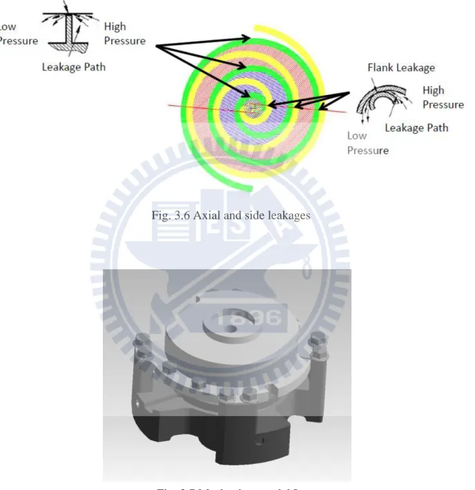
FIG.3.6AXIAL AND SIDE LEAKAGES ... 53
FIG.3.7MECHANISM MODEL I ... 53
FIG.3.8FEM MESH MODEL I ... 54
FIG.3.9FOUR FORCES ACTING ON FIXED SCROLL (MODEL I) ... 54
FIG.3.10TILTING MOMENT ON FIXED SCROLL ... 54
FIG.3.11ANSYS SIMULATION OF MODEL I ... 55
FIG.3.12SHAPES OF TWO LEAF SPRINGS OF MODEL I ... 55
FIG.3.13TEST RESULTS OF SPRING PROTOTYPE OF MODEL I ... 56
FIG.3.14SHAPE OF LEAF SPRING #SP-663 IN MODEL I ... 57
XIII
FIG.3.16MODEL FOR FEM ANALYSIS ... 59
FIG.3.17FINITE ELEMENT ANALYSIS RESULT ... 59
FIG.3.18PROTOTYPE OF ACM ... 60
FIG.3.19LIFTING SPRING THICKNESS VERSUS MINIMUM SPEED ... 60
FIG.3.20LEAF SPRING THICKNESS VERSUS POWER CONSUMPTION ... 61
FIG.3.21INVESTIGATION OF BACK CLEARANCE ... 61
FIG.4.1TEST RIG SCHEME AND EXPERIMENTAL SETUP:(A)MEASUREMENT SCHEME (B)PROTOTYPE FOR VARIABLE-SPEED EXPERIMENT ... 66
FIG.4.2NOISE VERSUS OPERATION CONDITIONS ... 68
FIG.5.1LIST OF R22 ALTERATIVE REFRIGERANTS ... 81
FIG.5.2DIFFERENT OPERATION CYCLES WITH DIFFERENT REFRIGERANTS ... 82
FIG.5.3COMPARISON OF REFRIGERANTS IN TERMS OF PRESSURE AND TEMPERATURE ... 82
FIG.5.4PRESSURE DROP IN CIRCULAR PIPE ... 83
FIG.5.5AXIAL CLEARANCE MODEL FOR GAS LEAKAGE TESTS IN STCS: ... 83
FIG.5.6LAYOUT OF LEAKAGE EXPERIMENTS WITH OIL-MIXING DEVICE [52] ... 84
FIG.5.7NUMERICAL SIMULATION RESULTS OF LEAKAGE EFFECT IN THE R410ALPSSTC ... 84
FIG.5.8NUMERICAL SIMULATION RESULTS OF LEAKAGE EFFECT IN THE R744LPSSTC ... 85
FIG.5.9CAE MODEL AND BOUNDARY CONDITIONS ... 85
FIG.5.10CAE SIMULATION RESULTS:AXIAL CLEARANCE ... 86
FIG.5.11CAE SIMULATION RESULTS OF ACM FOR R410A&R744STC PUMP ... 87
FIG.5.12RESULTS OF ANALYSIS OF FORCES IN BACKPRESSURE MECHANISM ... 88
FIG.5.13SECTIONS OF SEMIHERMETIC VERTICAL AND SEMIHERMETIC HORIZONTAL STC PROTOTYPES ... 90
FIG.5.14SEMIHERMETIC VERTICAL AND SEMIHERMETIC HORIZONTAL STC PROTOTYPES ... 91
FIG.5.15HERMETIC HORIZONTAL R410ASTC PROTOTYPE AND ITS TESTING ... 92
FIG.5.16COP PERFORMANCES OF PROTOTYPES ... 93
FIG.5.17R744 SEMIHERMETIC STC FOR CO2 HEAT PUMP WATER HEATER APPLICATION ... 93
FIG.5.18TESTING OF R744LPS HERMETIC STC FOR CO2 HEAT PUMP WATER HEATER APPLICATION ... 94
FIG.5.193D MODEL OF R744LPSSTC AND PROTOTYPE FOR CO2 BOTTLE COOLER ... 95
FIG.5.20CO2 BOTTLE COOLER LPSSTC PROTOTYPE ... 96
XIV
NOMENCLATURE
A cross-sectional area of the check valve, mm2
Ad discharge chamber area, mm2
Am middle chamber area, mm2
As suction chamber area, mm2
B scroll height, mm CR system pressure ratio Dl inner diameter of pipe, m D cylinder diameter, mm f friction factor
b
F backpressure gas force, N Fboss gas force on boss, N
bd
F
solid (body) force, N
Fdisk disk spring force, N
Fg axial gas force, N
m
F tangential accelerate force of scroll, N
F tangential gas force, N
Fpd net forces resulting from pressure difference, N Fpin gas force on pin, N
Fspring leaf spring force, N
t
F tangential force, N Ftx contact force, N
F_chamber chamber gas force, N
F_lower lower (suction) gas force, N F_backpressure backpressure gas force, N g acceleration due to gravity, m/s² hf head loss, m
Io moment of crankshaft, N-m
K spring stiffness
l scroll wrap thickness, mm
L sealing line length, mm Ll length of pipe, m
XV
center leakage
L , center leakage path, mm
circle leakage
L , circle leakage path, mm
M tilting moment, N-m
M Transfer matrix
Ms Orbiting scroll mass, kg Mo Oldham ring mass, kg
n normal vector of mesh point nf inner normal vector of mesh point
no outernormal vector of mesh point
N number of the leaf spring P pressure, MPa
Pcond saturated condenser pressure, MPa
Pd discharge pressure, MPa
Peva saturated evaporator pressure, MPa Pin_area backpressure pin area, mm2
Pm medium pressure, MPa o
P outer pressure, MPa Ps suction pressure, MPa
i
P inner pressure, MPa
r involute basic circle radius, mm rb base circle radius, mm
rm mean radius, mm
ro crankshaft radius, mm rs crankpin radius, mm R scroll wrap function
e
R Reynolds number
f
R fixed-scroll wrap function
o
R orbiting-scroll wrap function
p
R compressor pressure ratio
lc
R point of tooling edge
io
R inner scroll profile
fo
R outer scroll profile
oi
XVI
oo
R outer orbiting scroll profile
R moving vector of orbiting scroll s involute length, mm
1
S cutting tool center T temperature, ℃ t scroll thickness, mm
Tabi environmental temperature, ℃
Te evaporator temperature, ℃
Ts suction temperature, ℃
Tp scroll pitch, mm
T_condensor temperature of condenser, ℃ Tvi pressure valve temperature, ℃
V1 fixed scroll velocity, m/s
V2 tool movement velocity, m/s
V12 relative velocity, m/s
Vs suction volume, cm3 v velocity of fluid, m/s
X displacement of leaf spring, mm
Xc involute x coordinate Yc involute y coordinate
Greek letters
τ unit tangential vector
μ mn mean dynamic viscosity, Pa.s
ρ mn mean fluid density, kg/cm3
δ scroll clearance; scroll gap, μ m
δ a axial clearance, μ m
δ r radial clearance, μ m
u flow velocity in x direction ν flow velocity in y direction υ average viscosity, rad/s
ω tooling angular velocity, rad/s φ involute extension angle, rad φ i involute angle of the scroll, rad θ involute angle, rad
XVII
angle between the modified straight line and the x axis constant
axial empirical friction factor λ r radial empirical friction factor
Δ P pressure difference, MPa κ specific heat ratio
Subscripts
axial axial direction ar argument b base circle c center position dis discharge e end-side
fi_i inner involute of fixed scroll fi_o outer involute of fixed scroll
g gas
l,e end-side leakage l,f flank leakage ob orbiting scroll r radial direction t tangent coordinate tu tube a
1
CHAPTER 1 INTRODUCTION
1.1 Background
A scroll-type compressor (STC) (Fig. 1.1) is a kind of positive displacement compressor that is capable of both intake and exhaust in one compression cycle and has high efficiency, low noise, and few components. The concept for STC was derived from the U.S. Patent (Rotary Engine) granted to L. Creux in 1905 [1]. However, the name “scroll compressor” (or involute) was not used until the announcement of the U.S. Patent (Scroll Pump) by J. L. Jones in 1958 [2]. The STC has been extensively developed since the 1980s because of the great improvement in computerized numerical control milling. Further, it has been widely used by Hitachi since 1983 in small air conditioners.
The STC pump has two main components: a fixed scroll and an orbiting scroll. Each scroll has a circular base plate and an involute (spiral) profile protrusion extended from the plate surface. The involute wall has often been called a “scroll”. Fig. 1.2 shows the compression cycle of the STC. The scroll pair compresses the gas from the suction port into the chambers and pushes it progressively toward the center, gradually decreasing the volume of the gas until it reaches the discharger step. In this step, the gas is exhausted through the discharge port of the fixed scroll and then out of the STC to the condenser. Usually, after three rounds in the compression circle, the STC begins its simultaneous compression and discharge movements in several continuous symmetrical chambers. Therefore, the STC is operated with a low torque variation, low noise, and low vibration. Because of the absence of suction or discharge valves in the STC, the gas pulsation and flow losses can be reduced; this results in a smooth flow pattern, which indicates that the STC can start and restart easily. In addition, low flow losses result in a high volumetric efficiency, smooth operation, and high reliability.
Today, with the strengthening of effects of global warming and increase in awareness about energy conservation, attention worldwide has been focused on developing highly efficient compressors that consume low power. Therefore, in recent years, variable-speed STCs demonstrating optimum efficiency under different operating conditions have been studied. The operating conditions can be indicated and defined as the ratio of the saturated condenser pressure to the saturated evaporator pressure (Pcond/Peva) and can thus be determined for ambient operating
2
conditions. Further, the pressure ratio comes from the air-conditioner (or refrigerator) system phenomenon, and this influences the inner pressure difference (Pd/Ps) in the STC.
In general, the inner pressure difference arises from the compressor pressure ratio (volumetric ratio) has been fixed, as the geometrical parameters of the STC are set beforehand. The intrinsic limitation of the fixed volumetric ratio and the mismatch between the pressure and volumetric ratios of the STC cause over-compression or under-compression. Interestingly, inner leakage also causes a mismatch between the pressure and volume ratios. Thus, repetitive compression occurs and extra power is consumed.
Nevertheless, repetitive compression can be reduced by using a compliance mechanism incorporated in the fixed scroll to reduce inner leakage. However, tip leakage is a more serious problem than flank leakage [3]. Application of the axial-compliance mechanism (ACM) can decrease the inner leakage to match the varying operating conditions. Therefore, using the ACM, we can design and produce an STC having superior efficiency.
1.2 Motivation and objectives
For the energy-saving and environmental protection in modern high-efficiency inverter refrigeration and air conditioning systems, it is very important to improve the power consumption efficiency of the compressors.
In this study, the improvement of the STC’s performance is by introducing a new leakage-controlled mechanism, so called axial-compliance mechanism (ACM), to solve the internal leakage problem. However, the ACM mechanism design concept is come from patent research. For the understanding of the leakage mass flow rate is determined by the scroll profile, scroll constructions, scroll clearance size and operating conditions of the compressor. This study constructs a simple leakage model (transform the involute leakage path to a circular path) and integrates it into the developed STC-performance simulation package. From the numerically calculate using the STC package, the objective is to find out the best axial scroll clearance for design the optimum ACM and figure out the novel ACM design method.
3
clearance in an inverter driven variable-speed STC prototype. From the results of the experiments, the newly developed axial-compliance design should cause a considerable improvement in performance at both low and high operating speeds. Finally, the proposed ACM should be verified that it can apply in different refrigerant application with suitable design change.
1.3 Axial-compliance sealing methods
As the inner leakage can be minimized by several sealing mechanisms, it is important to solve the pressure-difference problem caused by the scroll pump for improving the sealing mechanism. This study has categorized the axial-sealing mechanisms for driving pressure difference into sealing forces. By reviewing over a thousand U.S. patents, we categorized the axial-sealing mechanisms of the scroll machines into four types:
(1) Tip sealing means on scroll wraps,
(2) Applying backpressure gas force to the back surface of the orbiting scroll, (3) Applying backpressure gas force to the back surface of the fixed scroll, (4) Using pressure members at the back of the fixed or orbiting scroll (or both),
(1) Tip sealing parts on scroll wraps
This kind of sealing method uses axial compliance with sealing parts to provide STC sealing. These parts comprise seal elements associated with the involute wraps, and the axial force forms a sealing contact with the end plates of the opposing scroll. The axial force may be applied pneumatically or mechanically. The axial contact resulting from the axial force is used to maintain the integrity of the radial sealing within the apparatus. The use of the axial compliance sealing allows the established contact between the end plates of the opposing scroll. The radial seal is machined to conventional accuracy and provides automatic compensation for temperature differentials and for any uneven wear of the scrolls.
4
(2) Applying backpressure gas force to the back surface of the orbiting scroll
This kind of sealing method uses an intermediate-pressure-level gas drawn from the operating scroll pump chambers during compression. This gas force is applied to the entire area of the back of the orbiting scroll to force the orbiting scroll tightly against the fixed scroll for providing an axial seal to the pair of scrolls.
(3) Applying backpressure gas force to the back surface of the fixed scroll
This kind of sealing method is used to enhance the axial sealing for a scroll machine, including a mu1ti-function floating seal, for isolating the axial biasing fluid from the working fluid under pressure; further, this method provides vacuum protection and maintains a high pressure ratio.
(4) Using pressure members at the back of the fixed or orbiting scroll (or both)
This kind of sealing method involves the use of a frame member having a thrust surface adjacent to the back surface of the orbiting scroll. A non-sea1ing stabilizer ring is disposed between the frame member and the orbiting scroll to eliminate the wobbles resulting from small perturbations. A stabilizer ring is mechanically or positively spring-loaded by a wave spring to axial force the orbiting scroll toward the fixed scroll.
Fig. 1.7 shows the gas–pressure distribution. The axial pressures cause the scrolls to separate. The tangential forces (F & Fm) result in an overturning moment and cause the scrolls
to wobble. Both of these behaviors result in leakage. The above sealing methods are used to solve the leakage problem using the four basic mechanisms.
5
1.4 Variable-speed STC
The STC was designed for operation at a constant speed by using a single-phase or multiphase induction motor for traditional refrigeration applications. This implies that the STC was suitable only for a specified operating condition or for thermal loading (cooling or heating capacity) with its best performance. If the STC was operated out of the specified condition, the performance decreased. In other words, the STC operating under one condition has high performance, but deviation from this specific operating condition results in various types of thermal loading owing to varied environmental temperatures.
Hence, in the traditional refrigeration applications, the STC switching on/off to match the different types of thermal loading once the environmental temperature changed. However, these switching actions caused unnecessary power consumption with loud noise and large vibrations in the pipes and the frame of the STC. Therefore, the STC did not have high efficiency when the operating speed increasing beyond the specific design point. The best approach for correcting the problem of on/off control of the constant-speed STC is to match the capacity of the air conditioner to the variation in thermal load. According to past research, the best solution is to use a variable-speed compressor for providing variable cooling capacity [4].
An inverter-fed controller for providing much cooling capacity to the varying thermal load drives the variable-speed compressor, which uses a variable-speed motor. In addition, the variable-speed compressor can replace a series of traditional constant-speed compressors. However, in order to enable variable-speed operation, balancing the inner forces and moments is essential. The best candidate for the variable-speed air conditioning system would be the STC wherein the chambers are compressed and discharged simultaneously at any speed and the characteristics of loading condition results in low-level vibration and small change in torque [5]. Therefore, the fluctuation in speed and the extent of mechanical vibration in the STC are considerably lower than those in the other types are. Because of the developed variable-speed STC, in this study, we implement an equivalent STC with an ACM to match the required performance under the extended operating conditions. Meanwhile, the performances of the developed STC with and without the ACM are compared.
6
1.5 Different sealing in low-side and high-side STCs
Two major configurations with different types of gas distribution housing are used in STCs: low (-pressure)-side (LPS) type and high (-pressure)-side (HPS) type. In the low-side type, the motor and the scroll set are located on the suction pressure side. The suction gas passes through the housing into the chamber around the compressor’s mechanism and motor. On the other hand, in the high-side type, the housing is filled with discharge pressure and the inlet is directly connected to the suction cavity.
Fig. 1.8 shows the schematics of these two types of STCs. The selection of shell configuration is a key determinant in STC design. The design configurations, forces generated by the scroll set during compression, leakage models, sealing mechanisms, oil lubricating flow designs, temperature distributions, noise controlling strategies, etc., are different for both types of STCs.
In 1992, Richardson and Gatecliff [6] presented the design requirements of the high-side and low-side types of the STC in detail. Further, they showed that the high-side configuration has several advantages, such as minimal suction gas heating and discharge pressure pulses, a simple axial and radial compliance mechanism, and a simple flow path for the lubricant. However, the drawback of this configuration is that the motor overheats easily under a high compression ratio and the STC has a low operating efficiency because of operation at a high discharge temperature and high oil circulation, which are not mentioned in the paper presented by Richardson and Gatecliff.
From an analysis of the launched commercial small STC products, we found that almost all the STCs that achieved high efficiency were developed with a high-side configuration. However, we believe the low-side STC could achieve high efficiency as high-side STCs are. For improving the low-side pressure type STC’s efficiency, the leakage problem needed to be solve first. Therefore, we adopted the STC developed by Chang et al. [7], which uses a low-side STC configuration, to be an original STC model.
7
1.6 Structure of dissertation
The contents of this dissertation are described below:
Chapter 1 briefly introduced the operation of the STC, the ACM for scroll sealing, and variable speed STC. The motivation and objectives also discussed in this chapter.
Chapter 2 presented the investigation of the leakage mechanism and the effect by the numerical analysis. In this chapter, a mathematical model was constructed and integrated into the developed STC package. The numerical simulation results of the leakage effect for different STC operation speeds also described in this chapter, which discussed in terms of energy conservation and performance improvement. These results will be verified by conducting experiments with one test platform constructed for an R22 LPS STC prototype with/without ACM mechanism in Chapter 4.
In chapter 3, the complete structure design of the ACM was presented. First, several important literatures were reviewed, and mathematical models depicting the geometry, thermodynamics, and dynamics of the mechanism, which are built on the basis of these literatures, were described. Case studies on designing the ACM module of STC products were introduced in section 3.3~3.5, which also presents numerical simulations and experimental studies. The results presented in chapter 4 show energy conservation and an improvement in the performance of the R22 LPS STC prototype at the extended operating speeds.
In order to understand how the thermo-physical characteristics of the refrigerant influence the ACM design, a study on the thermo-physical characteristics of the refrigerant comparison is discussed in Chapter 5 before presenting case studies of the R410A and R744 (CO2) LPS STCs
with ACM for air conditioning and refrigeration application. The scroll clearance for R744 LPS STC ACM design in our research is different from that in the studies presented in chapter 4. However, the pressure difference is the main issue in refrigeration application.
Finally, the important conclusions are summarized and future works are discussed in Chapter 6.
8
9
10
Fig. 1.3 Tip sealing means: Arthur D. Little, Inc., US 3,994,636, Nov. 30, 1976
Fig. 1.4 Pressurized gas to back of orbiting scroll: Hitachi, US 4,475,874, Oct. 9, 1984
Fig. 1.5 Pressurized gas to back of fixed scroll: Copeland, US 5,156,539, Oct. 20, 1992
11
12
13
CHAPTER 2 STUDY ON LEAKAGE EFFECT IN
LOW-PRESSURE-SIDE STC
2.1 Literature review
The STC is an important component of modern air conditioners because of its high efficiency, low noise, simple mechanism, and high reliability. Further, in recent years, studies on STCs have primarily focused on enhancing their performance by employing new technologies. For example, one such technology—the variable-speed control (or inverter-fed drive)—can improve efficiency and reduce energy consumption [8~10]. However, the construction of a variable-speed STC prototype is very expensive and impractical. Therefore, many researchers have employed numerical methods for investigating the performance of STCs.
Most of these numerical methods can be classified into two categories: “dynamic analysis of compliances” and “thermodynamic analysis of scroll operations.” The design theories of STCs and their geometric aspects have been reported previously [11] [12]. Further, investigations on the variations in the compressor performance when a self-adjusting backpressure mechanism is employed for axial compliance have been conducted [13]. A suction process using a dynamic model also has been analyzed [14]. The losses resulting from friction, compression, and leakage have also been studied via numerical analyses and experiments [15].
Most of these studies indicated that the friction losses were due to the contact behavior whereas the leakage losses were a result of the type of sealing between the orbiting and fixed scrolls. This is because the internal leakages not only decrease the cooling capacity but also influence the balance of inner forces, particularly at extended (both higher and lower) operating speeds. Therefore, it is extremely important to resolve the leakage problem for ensuring high reliability and energy conservation.
The abovementioned studies have also suggested that the best method for reducing internal leakage is to control the balance of internal forces of the compressor by using a compliance mechanism, which helps to maintain an optimal clearance between the scroll wraps. However, in the previous studies, the authors have suggested that the compliance mechanism is quite different in high-pressure shell (HPS) STC and low-pressure shell (LPS) STC. Both these STC types have significantly different methods for controlling the optimum scroll clearance because of the
14
differences in the characteristics of the pressure difference [16~18].
The previous literatures have also reported investigations on the leakage characteristics in STCs, such as leakage mass flow rate, leakage model, experimental investigations, and computational fluid simulations. However, few studies have been conducted on robust ACM designs for achieving energy conservation in an LPS STC operating at extended operating speeds.
In this study, a simple leakage model is constructed by transforming the involute leakage path into a half-circular path and is integrated into a previously developed STC-performance simulation package (ITRI_STC) [19]. Further, use this package with the parameters of a R22 STC model to simulate the inner leakage of the LPS STC via varying the clearance of scrolls. These numerical studies show an optimum clearance value for maintaining good cooling performance and high volumetric efficiency. The research results will possibly help in designing an ACM for improving the performance of STCs.
2.2 Numerical simulations of inner leakage effect
Leakage flows have been analyzed previously using various models [20~25]. In these studies, both theoretical and experimental investigations have been conducted for the analysis of leakage parameters [20~22]. These researches demonstrated that radial leakage (also called tip leakage) is more critical than flank leakage because the path of radial leakage is considerably longer than that of flank leakage (Figs. 2.1 and 2.2). In this study, the radial leakage problems are investigated. The results contribute to the enhancement of the effectiveness of the ACM design at extended operating speeds.
2.3 Mathematical model of radial leakage
Usually, most of the commercially available sealing part designs (such as floating tip seals [25]) are applied to reduce radial leakages and to prevent friction losses in the STCs. However, the use of seals in STCs increases manufacturing costs and requires precise assembly. Furthermore,
15
low operating speed and low pressure differences cause the floating tip seal to fail. Therefore, compressor designs without floating tip seals, which have low radial leakage, are being used by manufacturers such as Copeland, Hitachi, and Matsushita. In such designs, the radial leakage path can be considered as a circular path (Fig. 2.3).
The radial leakage is calculated by introducing a leakage flow on a one-dimensional flat plate [26] (Fig. 2.4). The direct leakage path is the scroll wrap thickness (can be considered as a constant value). Although the direction of the leakage path along the scroll curve changes with the orbiting angle, the typical path can be projected as several concentric circles, and the simplified leakage path is similar to the ring-type leakage path (Fig. 2.5).
We employed the following assumptions in this leakage model in order to simplify the numerical analysis:
(a) The leakage along the y direction is extremely small, as shown in Fig. 2.4, and can be considered to be related only to the pressure, temperature, and mean fluid density, along the x direction. ) ( ); ( ); (x T T x x P P mn mn (2-1)
(b) The fluid is a mixture of a refrigerant and oil and can be considered a Newtonian fluid.
y u mn (2-2)
(c) For small clearances, the flow direction can be considered one-dimensional; moreover, the velocity in the y direction is considered to be zero.
16
one-dimensional, which implies that the flow velocity in the y direction can be considered to be zero. (v0). 0 y v x u (2-3)
From assumptions (a) and (c), we can express the continuity equation as follows:
0 x u (2-4) Thus, the flow velocity is a function of the y direction:
) ( y u u
The momentum equation of the leakage flow is as follows:
) ( ) ( 2 2 y u v x u u y u x p mn mn (2-5)
From equations (2-1)–(2-5), we find that
dx dp y u mn 1 2 2 (2-5a)
The variables p, dp/dx, and µmn are independent of y. Equation (2-5a) can be integrated with respect to y with the following boundary conditions:
0 ) 0 (y
17 0 ) (y u
If the boundary conditions are substituted into equation (2-5a), the velocity distribution of the leakage depends only on the clearance, as follows:
dx dp y y u mn ) ( 2 (2-7)
Hence, the leakage mass flow rate ( dt ) dM is ) 6 ( 2 1 3 0 dx dp L udy L dt dM mn mn
(2-8)The distribution of the pressure in the leakage channel is considered linear as follows:
l p p dx
dp o i
The mass flow rate of the radial leakage can be calculated by
) 12 ) ( ( 3 l p p L dt dM mn o i mn (2-9)
This equation has several explanations:
(1) L
dt dM
; this shows that shorter the sealed length, the greater is the volumetric efficiency.
(2) The leakage mass is proportional to the scroll gap (δ).
(3) The leakage direction is identical to that of the pressure difference, and the mass leakage increases with the pressure difference.
18
(5) As the direction of leakage is orthogonal to the scroll velocity which is tangential to the base circle of the scroll profile, the leakage may not always increase (or decrease) by the component of the direction with the component of the same direction of the scroll velocity. However, the leakage decreases with an increase of the compressor speed is because the leakage time has become shorter.
By introducing the ring leakage model of the rolling piston pump [26], we find that the leakage model is based on several half-ring leakage paths that are equivalent to the original involute leakage path (Fig. 2.4). The scroll wrap thickness (l) is equivalent to the mean radius (rm)± half
the wrap thickness (
2
l
), whereas the mean radius is
2
L
(Fig. 2.4).
Finally, the radial leakage model is expressed as follows:
) ln( 6 ) ( 3 i o o i r r p p dt dM (2-10)
In equation (2-10), υ is an average value because it depends on the oil-mass percentage of the leakage fluid [26]. The overall leakage model assumed keeping in a thermal steady-state because of the compression chambers has been considered as a heat insulation system. The thermal dynamics calculation module is separator from the leakage module as the calculate flow chart shown in fig. 2.6. The leakage calculation module uses the thermal and pressure data from thermal dynamics calculation module, and it feedback the mass flow rate and leakage data to STC-package to calculate performance.
2.4 Case study on theoretical performance simulations
19
simulations of certain case studies using ITRI_STC [19] combined with the refrigerant data base named REFPROP 8 [27]. Fig. 2.6 presents the algorithm for calculating leakage.
The following three definitions of efficiency are employed for evaluating the STC performance, and their formulas follow those in Chang’s PhD thesis [28]:
(a) Coefficient of performance (COP)—the energy proportional to the cooling capacity and the power consumption of the compressor;
(b) Volumetric efficiency of leakage gas mass loss—the percentage of the ratio of actual mass flow rate (i.e., discharge mass flow rate with leakage) to the theoretical discharge mass flow rate;
(c) Isentropic compression efficiency—the ratios of the ideal isentropic compression work to the actual compression work (i.e., motor electric power consumption).
The main geometric parameters of the scroll in the LPS STC in this study are listed in Table 2-1, and the compressor’s operating conditions are listed in Table 2-2. In order to eliminate the influence of flank leakage, the flank clearance was set to zero during the numerical calculations. Figs. 2.7–2.10 show the results of the simulation; here, the scroll clearance (δ) was varied from 0 to 21 µm, whereas the operating frequency of the compressor was varied from 40 to 80 Hz.
Clearly, the findings indicate that the COP is inversely proportional to the leakage clearance (Fig. 2.7). Fig. 2.8 shows that the volumetric efficiency of the refrigerant mass loss decreased with an increase in the clearance value. Fig. 2.9 and Fig. 2.10 show the refrigerant flow rate and cooling capacity, respectively. From a comparison of these results, we find that the radial clearance should be limited to within 6 µm in order to maintain a high performance of the STC. These results also help in achieving better ACM designs and performances.
20
2.5 Remarks
The value of 6 µm for axial clearance was obtained for the given geometry and operating condition. The manner in which it can be affected by variation in geometrical and operating parameters is the most important aspect in this research for designing the ACM.
Discussions:
Changing both the geometrical and operating parameters may affect the optimum clearance value.
However, we find that if the geometry is changed, the axial leakage path and the scroll thickness may affect the optimum clearance value. We believe that there should be some relationship between the scroll thickness and the axial clearance. However, in this study, we assume that the axial clearance should be considerably lower than the scroll thickness (b), i.e., δ/b << 1.
If the geometry is not changed, the changes in the operating parameters can affect the pressure difference. The optimum axial clearance can be maintained by our ACM design because the backpressure pin design considers that the pressure difference originates from the different operating conditions.
21
22
23
24
(a) Involute leakage path scheme for leakage analysis
(b) Simplified half-circle leakage path for leakage analysis Fig. 2.4 Leakage flow simulation model
25
26
Fig. 2.6 Algorithm for calculating leakage
Suction Temperature &
27
28
29 0 0.5 1 1.5 2 2.5 3 3.5 0 3 6 9 12 15 18 21 24
C
OP
leakage clearance (μm)
COP value vs. leakage clearance
4800 rpm 4200 rpm 3600 rpm 3000rpm 2400 rpm
Fig. 2.7 Calculation results: COP value versus leakage clearance
0 10 20 30 40 50 60 70 80 90 100 0 3 6 9 12 15 18 21 24
volu
met
ric
e
ff
ici
e
n
cy
of mass Loss
(%)
leakage clearance (μm)
volumetric efficiency vs. leakage clearance
4800 rpm 4200 rpm 3600 rpm 3000 rpm 2400 rpm
30 0 50 100 150 200 250 0 3 6 9 12 15 18 21 24
ref
rigr
ant flow
r
at
e
(kg
/h)
leakage clearance (μm)
refrigrant flow rate vs. leakage clearance
4800rp m 4200 rpm 3600 rpm 3000 rpm
Fig. 2.9 Calculation result: Refrigerant flow rate versus leakage clearance
0 2000 4000 6000 8000 10000 0 3 6 9 12 15 18 21 24
coo
lin
g
capasi
ty (k
cal/
h
)
leakage clearance (μm)
cooling capacity vs. leakage clearance
4800 rpm 4200 rpm
3600 rpm 3000 rpm
2400rpm
31
CHAPTER 3 AXIAL-COMPLIANCE MECHANISM OF
LPS STC
A cross-sectional diagram of the ACM designed for an LPS STC is shown in Fig. 3.1. A scroll pump sucks the suction gas from the low pressure side (Fig 1.1), compresses it, and then discharges it at high pressure to the plenum (high pressure side); the exhaust is then emitted out of the discharge port. During compression process, the orbiting scroll continues to move with a wobble because of the inner unbalanced forces and tilting moments; moreover, the reaction forces and moments cause the fixed scroll to wobble as well. Therefore, in this study, in order to prevent the occurrence of clearances owing to the wobble phenomenon, in this study, the fixed scroll was pressed by a backpressure mechanism to trace the orbiting scroll in the vertical direction and the orbiting scroll was enforced (by the compressed gas pressure) to keep the base plate close to the surface of the trust bearing. However, the tangential gas forces cause the fixed scroll to wobble (Fig. 3.2). In the following subsections, the backpressure mechanism and suspension ACM designs for limiting the scroll wobble and maintaining the axial clearance near the optimum value (within 6 µm) are described.
3.1 Backpressure mechanism design
From the patent analysis, the patent US 6,368,088 Bl [29] shows the backpressure regulation mechanism for the fixed speed STC under different working conditions. The mechanism is operated by pressure different. However, to consider the behavior of LPS STCs under variable-speed operations, the most important factor is the variation in the pressure difference between the high and low sides in the STC. Using the pressure difference to drive the ACM could be the same function of US 6,368,088B1. Nevertheless, the backpressure regulation
32
mechanism using the significant changes in backpressure during the variable-speed operation of the compressor leads to the following two shortcomings.
(1) When the compressor operates at low condensation temperatures or at low pressure differences, the backpressure decreases, leading to poor sealing between the two scrolls and, hence, leakage. Moreover, in the case of excess leakage, the compressor cannot build up the pressure difference.
(2) The previous scenario reverses when the compressor operates at high condensation temperatures or at high pressure differences. Excessive backpressure increases the contact at the two scrolls and causes friction loss on the interface between the base plate of the orbiting scroll and the thrust bearing. This friction loss drastically increases the power consumption of the compressor.
For overcome the two shortcomings, a self-adjusting, robust design of the backpressure mechanism by forces analysis is proposed (Fig. 3.3(a)). Curve A represents the net force that can push and separate the two scrolls (this force is called the scroll separation force, and only its maximum value is considered here). Curve B represents the sum of the backpressure force by boss and the three pressure-pin forces by three backpressure pins due to the discharge pressure. However, curve B can satisfy the backpressure only during the rating operations. When the STC is operating at the under un-rating conditions, the pressure difference either decreases or increases whereas the backpressure correspondingly decreases or increases, respectively. Further, at low backpressures, the leakage loss increases, whereas at high backpressures, the friction loss increases. Furthermore, from the force analysis, the pre-pressing force value (Fs) can be
33
For providing an optimum backpressure, the backpressure force and the three pressure-pin forces should have a self-adjusting mechanism. (Fig. 3.4) Therefore, the optimum backpressure distribution curves should be curves C1 and C2, which provide a suitable and sufficient backpressure under any operating conditions. (Curve C1 represents the construction with the backpressure force, three pressure-pin forces, and disk spring forces. Curve C2 represents the construction only with the backpressure force and the three pressure-pin forces.) The designing points at P1 and P2 can be used to determine the point F1 and F2, respectively. Further, using the relationship between force and pressure, we can determine the backpressure areas via calculations.
The overall surface area of the boss and the pins can thus be determined which in turn determines the slope of Curve B. And the value of the area of the boss and the pins is also on the Curve C1 (called the point F1). From the same analysis, the overall surface area of the boss and the pins can thus be determined which in turn determines the slope of Curve C2, and the value of the area of the boss and the pins is also on the Curve C1(called the point F1). Fig.3.3(b) show the position design limited for the backpressure regulation pins. However, in this study, the position and location angles of the three pins are from the try-and-error method.
3.2 Suspension ACM design
In this study, an ACM design is developed to fine-tune the axial motion of the fixed scroll. In here, we take free body diagrams of each parts of the ACM (shown in fig. 3.4). The fig. 3.5 shows the exploded diagram of the suspension ACM. The design process of the two crescent leaf springs (as the elastic element) has been verified in detail by Tang et al. [30]. In their study, a design process was developed to determine the design parameters of the elastic element, and the
34
process was verified experimentally. Their results only demonstrate that the ACM can assist the compressor at low operating speeds from 50 Hz to 34 Hz under the rating conditions. Tables 3-1 and 3-2 list the results of the calculation of the inner forces for designing the backpressure and suspension ACMs, respectively. The tilting motion of the fixed scroll due to the tangential gas forces acted at the half-height of the scroll blend. As shown in Fig. 2.8, the limiting parts provided an anti-moment to overcome the tilting moment. Therefore, the contact noise and the leakage caused by tilting could be reduced.
3.3 Study on structural design and analysis of new leaf-spring-type
ACM
Several factors can influence the efficiency of an STC, and one of them is the internal leakage problem. However, the traditional mechanism for preventing internal refrigerant leakage in the scroll pump is a sealing mechanism to dynamically seal the scroll clearance caused by the unbalanced inner forces and moments in the STC. We know that the leakage path has been determined and the scroll line length has been designed. Radial leakage is larger than flank leakage because of its longer path. In this study, we discuss a sealing mechanism called a leaf-spring-type ACM, and this mechanism could improve the volumetric efficiency and increase the cooling capacity.
The compliance mechanism is used for controlling the floating tolerance of the fixed scroll between the frame and a separate plate and for keeping the radial leakage to minimum. Further, the compliance mechanism is used for solving the incongruity in the backpressure of the fixed scroll in the axial direction, which can increase the forces exerted from the fixed scroll to the orbiting scroll. This backpressure causes more friction loss, which can induce a decrease in the
35
compressor efficiency. For eliminating the unnecessary losses, we consider case studies on designing an ACM with a leaf-spring structure to limit the floating distance of the fixed scroll and to keep the tip clearance in the optimum state. From finite element analysis and the experimental tests on the prototype, we find that this new sealing-function module can reduce noise and increase the cooling performance.
3.3.1 Literature review
In recent years, power conservation has become a critical aspect in the air conditioner and refrigerator industries. In order to conserve the electric power, improvement in the performance of a compressor has been proposed, which has led to considerable research on the behavior of leakage in a scroll pump (The internal leakage of a scroll pump can decrease the cooling capacity and increase the power consumption.) under the operating conditions (see Fig. 3.6). Tojo et al. [31] have proposed a self-adjusting backpressure mechanism for a HPS STC, wherein the fixed scroll is fastened to a frame and the orbiting scroll floats under the gas pressure between the fixed scroll and the frame. Suefuji et al. [32] have presented a method for calculating the performance of a hermetic STC by using a simplified thermal analysis model. Bush et al. [33] have discussed the stability characteristics of the backpressure-supporting orbiting scroll. Marchese et al. [34] have discussed the dynamics of an orbiting scroll with axial compliance.
Lee et al. [35] have proposed an optimum ACM for the LPS, which can increase efficiency by 15% under a fixed operating frequency. Park et al. [36] have discussed the results of the thermodynamic analysis of the performance of a variable-speed STC with refrigerant injection; however, the ACM has not been discussed. In any case, research and information on developing an ACM for the tip leakage of scrolls in a LPS STC are insufficient, particularly under a low operating frequency. This study presents a suspension-compliance mechanism in a LPS STC (see
36 Fig. 3.7).
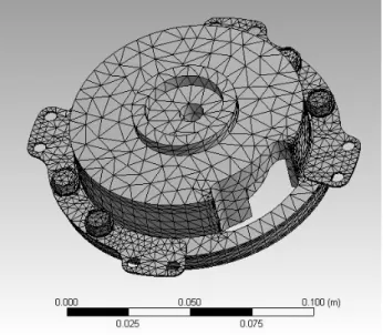
This mechanism, using two leaf springs, can prevent scroll tip leakage and help to reduce the scroll contact noise. Normally, the fixed and orbiting scrolls in an LPS STC are subjected to unbalanced forces and moments that can cause the scroll plate to tilt, which causes leakage, noise, and additional frictional wear. With a suitable design such as the one proposed here, the compliance mechanism can eliminate the unbalanced forces on the scrolls, and prevent the additional frictional forces between the scroll tips during the operation of the STC. Several numerical methods have been adopted in this study. For example, a finite element model (FEM) code (ANSYS) has been used to predict the deformation in the compliance, and a compressor-performance simulation package developed by ITRI has been used to calculate the gas forces for the FEM boundary conditions. Further, the clearance between the two scroll tips has been optimized to design a leaf spring of suitable thickness (Fig. 3.8).
3.3.2 Basic analysis of inner force for the ACM design
To simplify the analysis of the proposed mechanism, the following basic assumptions are made:
1. The fixed scroll has a limited floating displacement in the axial direction.
2. Only four dynamic forces directly acting on the fixed scroll are calculated precisely.
The contact force between the orbiting scroll and the fixed scroll resulting from a tilting moment on the orbiting scroll is assigned a constant value determined on the basis of previous studies. In this study, the four dynamic force categories are axial gas pressure forces, leaf spring forces, pressure pin forces, and backpressure forces (see Fig. 3.9). During operation, the axial
37
clearance between the fixed scroll and the orbiting scroll is determined by the equilibrium of forces. The resultant force pushes the fixed scroll, eventually leading to contact between the fixed scroll and the orbiting scroll. This causes a frictional force, noise, and unnecessary mechanical contact vibration. These four force categories are defined as following.
I. Backpressure Force
The backpressure force is generated by the discharge gas pressure acting on the check valve, and it can be calculated from the following equation.
b d
F P A (3.3.2-1)
Here, Fb is the back force of the gas acting on the check valve; Pd, the discharge gas pressure
from the backpressure chamber; and A, the cross-sectional area of the check valve.
II. Pressure Pin Force
The pressure pin force is caused by the pressure difference between the suction gas and the discharge gas in the high backpressure chamber acting on the pressure pin surface and by the downward force of the fixed disk spring. It is calculated from the following equation:
( ) 3
pin disk pd
F F F (3.3.2-2)
where Fdisk is the disk spring force and Fpd is the net forces resulting from the pressure difference
between the suction gas and the discharge gas in the high backpressure chamber acting on the pressure pin surface. Three pins considered in this analysis.
38
III. Axial Gas Force
The axial gas force is caused by the pressure distribution in the compression chambers between the fixed and orbiting scrolls. The axial force acting on the fixed scroll is calculated
from the following equation:
g d d m m s s
F P A P A P A (3.3.2-3)
where Fg is the axial gas force; Pd, the discharge pressure;Pm, medium pressure; Ps, the suction
gas pressure; Ad, the area of the discharge chamber, Am, the area of the middle chamber; and As,
the area of the suction chamber.
IV. Leaf Spring Forces
The total force caused by the displacement of the leaf spring is computed by the following equation:
s
F NKX (3.3.2-4)
where N is the number of leaf springs; X, the displacement of the leaf spring; and K, the spring stiffness.
During the operation of the scroll, a tilting moment is exerted on the orbiting scroll, which can result in the application of a contact force to the fixed scroll (see Fig. 3.10). The contact force is a major cause of the decrease in the compression efficiency and an increase in the noise level. The resultant four dynamic forces need to be designed suitably for achieving stable motion. This can be achieved by satisfying the following conditions.
39
( )
b g tx
F F F (3.3.2-5)
Here, Ftx is the contact force. It is difficult to precisely calculate the value of Ftx. In general
compressor design, a random value is initially assigned to Ftx on the basis of previous studies.
3.3.3 CAE simulation model for improving ACM design
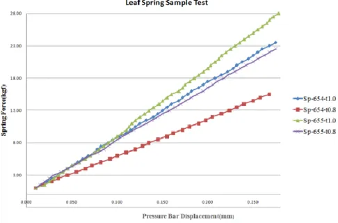
In order to design a leaf spring of appropriate thickness used in the prototypes, a finite element simulation package (ANSYS) [37] is employed to calculate the axial displacement of the leaf spring. The active forces calculated from the compressor-performance simulation software (developed by ITRI) are introduced as the boundary conditions. In the FEM model, the leaf spring is made of SKD11 steel; the scrolls, FC300 cast iron; and the fixed ring for the fixed scroll, AISI 1040 steel. Further, all the screws are made of SCM435 steel. The FEM is shown in Fig. 3.8, and the results of the simulation are shown in Fig. 3.11. According to the results of the FEM analysis, four leaf-spring prototypes are fabricated by two different thicknesses (0.8 mm and 1.0 mm) and two shapes for further experimental analysis.
3.3.4 Prototype experimental results
For comparing the results of the FEA simulations and the universal testing machine tests, a preliminary experiment is conducted by controlling the clearance and measuring the reaction forces acting on the prototype that uses a scroll-pump assembly as shown in Fig. 3.13. Another experiment is conducted in a compressor-performance testing room (in ITRI), and the operating conditions are as listed in Table 3-3. All the tested prototypes are operated at the rating speed (3600 rpm).