111Equation Chapter 1 Section 1
Abstract— Fully-packaged acoustic power receivers are introduced. They can provide electronic energy to other implanted devices by receiving an external acoustic wave generated from the skin surface of the subcutaneous tissue. Piezoelectric ceramics make the internal devices of the receivers, and they are directly charged, converting pressure into an extractable electrical energy. Moreover, cohesive gel is used to package the internal devices, and the packages are biocompatible and sufficiently soft to absorb the incident wave that is generated at the skin surface. Additionally, the effects of the shape of the scattering package and ratio of the stiffness of the package to that of the tissue are considered in designing the receivers. The dominant frequencies and the energy efficiency of the receivers are measured in the very streaky pork, which is used to simulate human subcutaneous tissue. The results indicate that the spherical packaging is preferable to the cubic packaging when buried in the muscular layer. The maximum efficiency of the power transmission is found to be –48.2 dB, using the spherical package in the muscular layer of the streaky pork.
Index Terms— acoustic devices, piezoelectric resonators, and power transmission.
I. INTRODUCTION
THE application of micro-system technology to biomedical monitoring is currently being extensively investigated nowadays. However, wireless power supplies for implantable biomedical chips remain a large challenge. Much effort has been made to develop miniaturized power generation systems for use in implantable micro-devices. Power harvesting and power transmissions are frequently-used methods to enable the requirements of recharge and long lifetime to be met. Typical power harvesting devices utilize piezoelectric microstructures that are excited by random environmental vibration to convert mechanical energy to electric power [1]-[3]. Biological fuel cells which use oxide glucose to produce electricity can also be considered as power harvesting systems with implanted capacity [4], [5]. In comparison, power transmission provides a higher power density than power harvesting [6].
Electromagnetic and acoustic waves are two typical carriers for delivering energy through the human skin and the human body. Unlike electromagnetic power transmission, acoustic transmission prevents electromagnetic interference in the
Manuscript received June 18, 2009. This work was supported by the National Science Council, Taiwan, with the project numbers NSC 95-221-E-002-203- MY2.
Po-Jen Shih is with the Department of Civil and Environmental Engineering, National University of Kaohsiung, Taiwan (corresponding author to provide phone: 886-7-591-6592; fax: 886-7-591-9677, e-mail: [email protected]).
Wen-Pin Shih is with the Department of Mechanical Engineering, National Taiwan University, Taiwan (e-mail: [email protected]).
implanted bio-electrical instrument and is associated with lower power attenuation in the presence of water in the body.
The mechanism of acoustic power transmission differs from those associated with ultrasonic medical imaging. A medical imaging machine sends an ultrasonic wave into the tissue from the skin surface or the buried piezoelectric emitters [7]. It then detects the reflected wave and analyzes the diseases at the skin surface. On the other hand, a power transmission system receives acoustic waves and then converts the received mechanical energy into electricity. For the shallowly implanted medical devices, the earlier works invent the implantable medical designs including piezoelectric devices and the charging battery [8] and provide the optimum resonance frequency of the transmission system [9]. Deeply implanted medical devices suffer from significant amount of noise in received signals due to complex wave scattering effects; conversely, without considering the signal identification, the noise affecting the efficiency of the acoustic power transmission is not as strong. However, wave attenuation along the travelling path associated with diverse tissue characteristics in subcutaneous layers must be considered [10]-[12].
This work uses a low-power acoustic emitter to transmit energy from the surface of the subcutaneous tissue to the implanted miniature devices. It can be used to recharge implanted batteries or to supply energy to specific implanted micro devices such as drug delivery systems, which are implanted in deep tissues where the acoustic attenuation is serious. To realize a portable recharger, the emitting system is a piezoelectric buzzer element, which is triggered by ±5V and is inputted power of 1.23 mW to generate acoustic signals. The acoustic power receiver should be fully-packaged with biocompatible materials. In the aspect of power transmission, the power generated by the receiver can be always increased by enhancing the acoustic energy. However, proper packaging design of the system is important to enhance the power transmission efficiency and is focused in this paper.
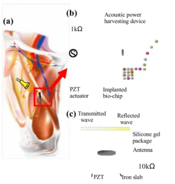
The proposed receiver is implanted in the subcutaneous tissue (Figs. 1a and 1b). It is based on a micromachined piezoelectric transducer that is packaged in cohesive gel [13]. When a low-power piezoelectric generator emits sinusoidal acoustic waves at the external skin surface, an acoustic field is produced in the subcutaneous tissue. Then the acoustic wave propagates into the cohesive gel package. The proposed cohesive gel package is biocompatible. It is also sufficiently soft to absorb the incident wave and to conduct the mechanical pressure to the transducer. The transducer consists of a thick piezoelectric film, on which an attached aluminum antenna can receive the acoustic energy. The piezoelectric film is sandwiched between the parallel electrodes which extract the
Design, Fabrication, and Application of
Bio-implantable Acoustic Power Transmission
polarized charges and thus to generate electricity.
The power transmission efficiency of the proposed device under the applied acoustic fields of various frequencies is examined. The scattering effects due to the shape and material properties of the package are investigated by using finite element modal analysis. The fabricated power receivers are experimentally tested inside very streaky pork to simulate human subcutaneous tissue. The experiments are conducted in single fatty tissue, single muscular tissue, and double-layered fatty-muscular tissue, respectively. The frequency spectrum of the power transmission efficiency is obtained from different tissue layers.
II. DEVICE DESIGN
A. Design Concept
The acoustic power receiver is designed to recharge implantable bio-chips and must satisfy three major requirements. First, the package of the power receiver must be biocompatible. Second, the power receiver must be able to absorb acoustic energy from the muscular environment. Third, the power receiver must be able to effectively transform the acoustic energy into electricity.
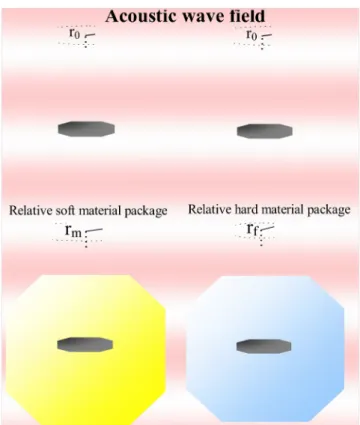
The cohesive gel is used as the package material to meet the requirement of biocompatibility. Additionally, it does not decompose or swell in water [13]. To satisfy the second requirement as aforementioned, the Young’s modulus of the package material must be relatively lower than that of the muscular tissue. Otherwise, most of the acoustic waves would be scattered away from the package-tissue interface due to the increase in the mechanical impedance. Under such circumstances, the power transmission efficiency falls. Notably, the Young’s modulus of the muscle depends on the age and the location in the human body [14]-[16]. Herein, the cohesive gel has a Young’s modulus lower than the general human tissues do and so it can effectively eliminate scattering.
In addition to the Young’s modulus, the scattering effect of the package shape must also be considered. This investigation studies cubic and spherical cohesive gel packages (Fig. 2). The dimensions of the cubic package are 10x10x5.5 mm3, and the
radius of the spherical package is 5 mm, as presented in Table I. These two packages have the same cross-sectional areas, on which incident waves impinge vertically but different refractive effects because the incident angles differ. The power receiver is packaged within the cohesive gel. It has an acoustic antenna which can effectively collect the acoustic energy. The antenna receives the refractive waves that propagate through the package, and so it excites vibration at its resonance frequency. The antenna is attached to an iron slab and exerts stresses to the iron slab during vibration. Then the slab stresses the piezoelectric resonator that is underneath, generating electrical charges (Fig. 1c).
The antenna is an aluminum circular plate, and the design concept follows the ultrasonic transducer as a modeled in [17]-[19]. The circular shape is corresponded to the spherical package. The center of the plate is slightly concave by
embossing to mechanically support the antenna on the iron slab. The material of the antenna should be stiff enough to avoid unexpected bends. Aluminum was chosen as the antenna material to reduce weight. To maximize reception of the refracted wave, we locate the antenna in the middle of the spherical package to meet its maximum refractive area. Other package geometries can also be applied if the cross-sectional area of the antenna maximizes reception of the refracted wave. To get a better response at the resonance frequency, we do not suggest asymmetric package geometries because they may generate complicated scattering patterns and increase noises. Moreover, the spherical device is directional, and the beam angle patterns are shown in [20].
For the specific cases in Table I, a simple sketch presents the transition efficiency as functions of the material property ratios of the cohesive gel to the tissues and the shape of the package. For the material property, a lower Young’s modulus is associated with a lower wave speed that has a higher refractive energy. The speed of the acoustic wave is given by
(1 ) (1 )(1 2 ) L E C , (1)
in which is the Poisson’s ratio; is the mass density; and
E is Young’s modulus. Moreover, ignoring secondary
reflection and refraction inside the package yields the displacement amplification for a single boundary problem [21], 2 / L refraction incidence P P L L C D D C C . (2)
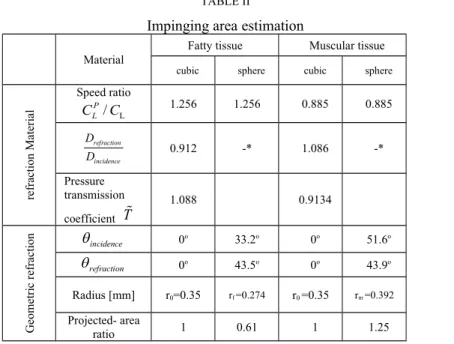
in which the incident angle is assumed to be zero, and the superscript “P” denotes the material property of the package. Therefore, a lower wave speed of the package is responsible for a higher refractive displacement, as presented on Table II. The displacement amplification in the muscular tissue is greater than that in the fatty tissue by 1.19 times. Moreover, the pressure transmission coefficient is defined by the ratio of pressures 2 / P P L refraction incidence P P L L C T p p C C , (3)
and the results show that T1 in the muscular tissue but 1
T in the fatty tissue. The result indicates that the fatty tissue reflects more energy at the interface. As a result, the acoustic impedance matching in the muscular-to-package interface transfers more acoustic energy into the package than the fatty-to-package interface does.
The refractive angle of the acoustic wave depends on the ratio of the speeds in the two media. The geometric shapes of the packages may help to increase the impingement of the
refractive wave on the antenna. The relationship between incidence and refraction is
sin P P/ sin
refraction CL CL incidence
, (4)
in which the incident angle incidenceand the refracted angle refraction
are taken from the normal vector of the interface, as presented in Fig. 2. Moreover, the received energy depends on the projected area of the package that is impinged upon, and this area is related to the area on the antenna. Based upon Table I and Eq. (4), the projected area of the package can be calculated. In Fig. 2, the radius r0 denotes the effective radius
of the projected area of the cubic package that is impinged upon, and radii rf and rm are that of the spherical packages in
fatty and muscular tissues. Consequently, in muscular tissue, the spherical package has 1.25 times the projected area of the cubic package. However, in fatty tissue, the spherical package has 0.61 times the projected area of the cubic package. Table II presents the results in detail.
B. Numerical Simulation
Finite element simulations are carried out to validate the design concepts and to improve facilitate out the understanding of the propagation of waves inside packages. The power receiver is buried inside the muscular tissue at a depth of 15 mm.
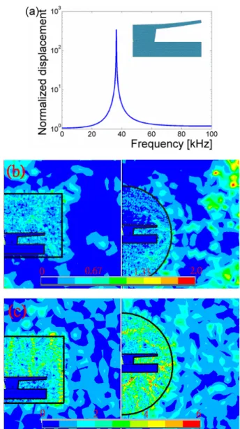
A modal analysis of the power receiver in the absence of a package and surrounding tissues is conducted. The simulated frequency response in Fig. 3a demonstrates that the first resonance frequency of the power receiver is 36 kHz. The inset in Fig. 3a presents the corresponding mode shape of the receiver. The mode shape of the antenna monotonically bends upward at the first resonance frequency. The resonant frequency of the bulk subcutaneous tissue is also simulated. The major resonant frequency of the bulk subcutaneous tissue is below 1 kHz. Therefore, the transmitted acoustic energy is not trapped in the subcutaneous tissue if the frequency of the transmitted acoustic wave is close to 36 kHz.
The models of the complete packages buried in the fatty and muscular tissue are established. The same frequency, 36 kHz, as mentioned above is applied to the packages. Figures 3b and 3c plot the sums of the displacement vectors for cubic and spherical packages. One unit of pressure is applied to the surface of the muscular tissue. Since the dominant frequencies of the muscular tissue are well below that of the internal micro-device, they cannot efficiently trigger the muscular tissue but only the area located inside the packages. The main responding areas in the cubic and spherical packages occur at the top and at the spherical boundary, respectively. In the figures, in muscular tissue, the spherical package exhibits about 1.37 times the normalized displacement of the cubic package. However, in fatty tissue, the spherical package exhibits 0.82 times the normalized displacement of the cubic package.
In conclusion, the numerical results reveal the characteristics of the internal micro-device with two forms of
packaging, and the results elucidate many of the phenomena associated with the packages of interest. And burying a spherical package in muscular tissue is favorable.
C. Fabrication
The process of fabricating the complete power receiver can be divided into the fabrication of the internal micro-device and the packaging procedure. Quality checks are also important.
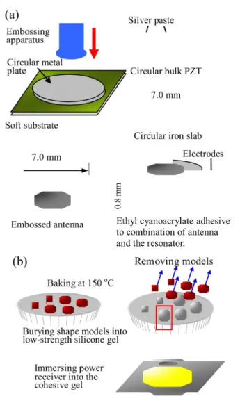
Firstly, the internal micro-device is fabricated by attaching the antenna onto an iron slab, and then the PZT unimorph is attached under the slab, as shown in Fig. 4a. The antenna is formed by hard- embossing a circle onto an iron disk. The PZT unimorph is a circular bulk PZT ceramic that is covered with a silver paste on both sides, with an iron slab attached to the topside, and the material properties of the PZT are shown in Table I. This iron slab is used to transmit the stress from the antenna to the PZT material. Ethyl cyanoacrylate is used to attach the antenna and to the PZT unimorph. Notably, the quality of this bond affects the power performance of the stressed PZT. The fabrication of the internal micro-device is completed by welding the electrodes onto the silver pasted sides.
The second step is the packaging procedure, displayed in Fig. 4b. The procedure begins by molding the model shapes. Low-strength silicone is chosen as the mold material because it is easily destructively peeled off from the package material, which is cohesive gel. After the shape models are molded, they are removed. Then the internal devices are placed into the molding shapes, and the cohesive gel is injected into the molds. After that, the gel-filled molds are placed in a vacuum chamber to remove air bubbles, and the gel is solidified at 150oC for 45 minutes. After the molds are removed, the
micro-device is fully packaged, as shown in Fig. 5a and 5b. Notably, care must be taken, in removing the molds and maintaining the sought shapes of the cohesive gel.
The quality checks have two parts: the checking of the internal micro-device and those of the complete package. For the first, the internal micro-device is used to detect an acoustic source that is traveling in air to ensure that all of the details of the results are correct. The second check must be performed under buried conditions because the traveling acoustic wave is easily transmitted through the cohesive gel. A circuit should be observed when the entire package is buried in the subcutaneous tissue. The signals are measured, and the dominant frequency in the data measured from the oscillograph is checked to ensure that it matches the input frequency from the function generator.
The fabrication procedure is followed by combining of the internal micro-device, the molding of the packaging, and the testing of quality.
III. EXPERIMENTAL RESULTS
To characterize the fabricated receiver and to compare its performance with its numerically simulated performance, its power transmission efficiency and frequency are measured when it is buried in air, cohesive gel, and very streaky pork.
A. Testing Internal Micro-device
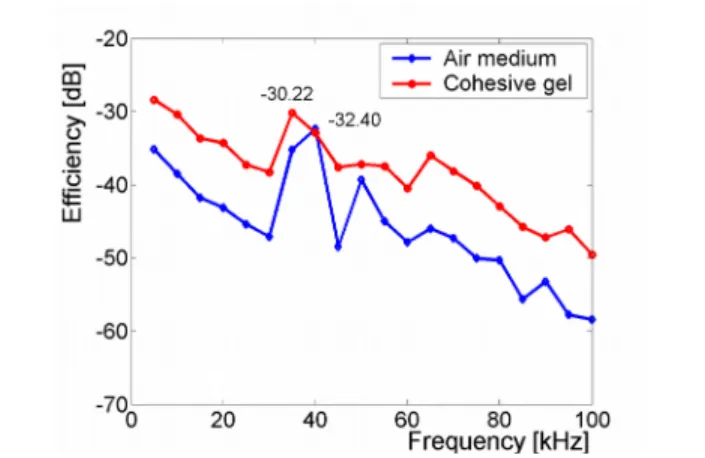
Measuring the characteristics of the internal micro-device is the first part of the experiment. The dominant frequency is around 40 kHz, displayed in Fig. 6, when the test is conducted in an opened air acoustic system, at a distance from the emitter of 15 mm, and the acoustic wave impinges directly on the internal device. The emitter is triggered by the function generator with ±5 V sinusoidal signals and a resistance of 1kΩ, and the receiver is series connected in series to a resistance 10 kΩ, as displayed in Fig 1. The power efficiency is given by a ratio of the energy of the emitter and that of the receiver, i.e.
Efficiency[dB] 10log[ Pout/Pin], (5)
in which P and in P are power emitted and received,out
respectively. Here P is modified by its phase angles within
various frequencies, and P is calculated by dividing theout
square of the output voltage by the electrical load on the receiver. The efficiency denotes the power amplification of the receiver with respect to the acoustic intensity level of the source. The acoustic emitter is a piezoelectric buzzer element with 2.8±0.5 kHz resonant frequency and 300 Ω resonant impedance. Herein, the emission frequencies of the acoustic waves varied from 5 kHz to 100 kHz. The measured results are close to the numerically simulated frequency of the first model of the internal device. Moreover, the dominant frequency of the device without a package is also measured through burying in pure material of cohesive gel. The internal device is buried at the centre of a gel pillar with a diameter of about 80 mm, and the distance between the emitter and the receiver is 15 mm. The results in Fig. 6 also indicate that the efficiency of the device buried in the gel exceeds that of the device buried in air. It can be due to that the acoustic impedance matching in the path through emitter-to-gel and gel-to-device interfaces transfers more energy than does the path through emitter-to-air and air-to-device. The shift of the dominant frequency down to 35 kHz from 40 kHz is due to the mass loading effect of the gel. The polarization of the receiver buried in a spherically packaged case has been presented elsewhere [20].
B. Testing of Receiver Buried in Single Layered Tissue
The next step is to estimate the power transmission efficiency of the receivers that are buried in a fatty layer and in a muscular layer, respectively. Fig. 7a and 7b display the respective experimental setups; and the thicknesses of the fatty and muscular tissues are 60 and 45 mm, respectively. The acoustic emitter is adhered to the bottom surface of the tissue without any air gaps, and the receiver is buried inside the tissue 15 mm from the emitter. The two packages are tested in two media, and Figs. 8a and 8b plot the power efficiency in relation to the frequency spectra from fatty and muscular tissues, respectively. The results show that the dominant frequency is 35 kHz for both packages in both tissue layers. It
indicates that the mass loading effect can be attributed only to the gel in the proximity of the internal device and is irrelevant to the package shape and the tissue materials. The results in Fig. 8 also indicate that the wave attenuation through the cubic package in the fatty tissue at the peak efficiency is 13.05 dB stronger than that in the muscular tissue. The different attenuation behaviors can be explained by the acoustic impedance matching because the transmission coefficients of material properties are 1.088 relative to 0.9134 as indicated on Table II.
The spherical case outperforms the cubic case about 3.94 dB when each is buried in the muscular tissue, but the cubic case outperforms the spherical case about 17.12 dB when each is buried in fatty tissue. The spherical geometry hardly absorbs the incident wave because the projected area ratio of the geometric refraction is 0.61 as indicated on Table II. The result of the experiment is also consistent with the design concept illustrated in Fig. 2.
Summarily, the fact that the spherical package buried in fatty tissue has the lowest power efficiency is due to not only the geometric effect but also the material properties in the aspect of acoustic impedance matching.
C. Testing of Receiver Buried in a Double Layered Tissue
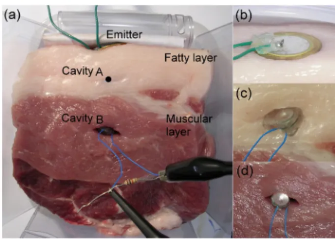
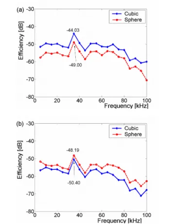
The efficiency of the receivers when the device is buried in very streaky pork is also tested. The streaky pork is a two-layered material, in which the fatty layer is above the muscular layer. The acoustic emitter is adhered to the top of the fatty layer, as shown in Fig. 9a. The fatty layer is only 30 mm thick, while the muscular layer is 70 mm thick. The test is performed at two carved cavities, one each in a fatty layer and in a muscular layer, respectively. The cavity in the fatty layer is 15 mm below the surface of skin, and that in the muscle layer is 15 mm below the fatty-muscular interface. The experiment is started at the muscular layer because the pre-carved cavity may interfere with the path of the travelling waves. In addition to the cavities, the acoustic wave is emitted from the top surface through the fatty layer and into the muscular layer. The cubic and spherical packages are tested in each carved cavity. In Fig. 10a, the efficiency spectrum indicates that the cubic package outperforms the spherical package by 4.97 dB when both are buried in 15 mm of the fatty layer. In Fig. 10b, the spherical package outperforms the cubic package by 2.21 dB when both are buried in 15 mm below the fatty-muscle interface. These results correspond to the significant geometric effects at the interface of packages. Indeed, these results are similar to those in the single layered case in Fig. 8, except the high efficiency of the cubic package buried in a single layer of fatty tissue. The value differs from -38.16 dB to –44.03 dB. The high efficiency in Fig. 8a can be deduced to that the thick fatty layer, about 60 mm, that has free boundaries. Free boundary may trap the incident acoustic waves which repeatedly traverse the cubic package due to reflections at the boundaries; otherwise, the waves are reflected from the surface of the spherical package every time. In addition, the attenuation of the travelling wave from top to bottom can be observed by comparing Fig. 10b with Fig. 10a. This
attenuation can be examined in terms of the impedances of the fatty layer, muscular layer, the emitter-fatty interface, the fatty-muscular interface, and the muscular- package interface.
IV. DISCUSSION
The power efficiency of the implanted device depends on the depth of the device, the acoustic frequency, the material properties of the tissues, the emission system, the reflection loss, and the refractive absorbability of the device.
For wave propagation, long traveling path causes serious attenuation. Compared with shallowly implanted devices, such as the cardiac pacemaker, the defibrillator, and the nerve/muscle stimulator, the current device is aimed at the devices embedded in deep tissues, such as drug delivery systems for the prostate gland, the mammary glands, or some devices used in the intra abdominal space. Because of the serious attenuation, this study also takes the geometric shape of package into account to absorb energy.
The power efficiency also depends on the frequency of the travelling wave. High frequency waves attenuate quickly, and the triggering frequency has to match up the dominant frequency of the receiver. In this study, the best performance is triggered at 35 kHz, which is the resonant frequency of the internal device. Furthermore, the frequency at 35 KHz is not too high when compared with other studies [8][9].
The material properties of the subcutaneous tissue are discussed by the types and the stability. For the types of tissues, the transmission efficiency relies on the impedance matching in paths of emitter-to-tissue and tissue-to-package interfaces. For the stability of the experiments, it has been noticed that the material properties of the subcutaneous tissues are unstable. Since organisms, comprising of cells, biological tissues, and organs, are not homogeneous, the interaction of a wave and an organism is more complex than other materials. Additionally, the material properties of the organism may vary with saturation, marbling, pressure, temperature, and time [22]-[24]. Similar experiments may yield different Young’s moduli if the pork is exposed to air for hours, so the temperature of the pork must be controlled to freshness of the pork.
An appropriate emission system is considered to improve the transmission efficiency on the tissue surface. Firstly, the diameter of the emitter should be larger than (d+2h), in which
d denotes the diameter of the receiver and h denotes the depth
between the emitter and the receiver. Secondly, intimate contact between the emitter and the tissue surface is required. Acoustic gel, in medicine, is useful for the purpose. In the cases, however, the buzzer elements are seriously adhered onto surfaces by liquid instant glue. Furthermore, the external pressure on the surface of the emitter must also be considered in the experimental procedure. In addition to the current buzzer emission, some novel studies discuss about mechanism devices and geometric arrays for the optimization of high power transmission, for example, the capacitive MEMS ultrasonic transducer [25]-[27].
The reflection loss depends on the impedance matching at
the paths by the interfaces, such as the emitter and tissue, tissue and package, package and internal device, as discussed in Section III. In addition, the refractive absorbability of energy depends on the shape of the package. In this study, the efficiency of the impinging wave reduces by –32.4 dB in the cohesive gel (only internal device), by –44.03 dB in fatty tissue (cubic package), and by –50.4 dB in muscular tissue (spherical package), when the emitter is triggered at 35 kHz. The spherical package is associated with greater efficiency of the receivers than is the cubic package in a muscular cavity; however, the efficiency of the cubic package is greater than that of the spherical one in a fatty cavity.
In addition to the power efficiency, the recharge duration is considered. The power of the emitter triggered at 35 kHz is 1.23 mW. Under this condition, the receiver in spherical case buried in single muscular tissue can generate 23 nW power. When considering the battery for the drug delivery system, the power requirement is still uncertain. Although a heart pacemaker is not appropriated here, its required capacity of battery is just taken as an example [28]. The required power for the battery is 25 μJ, and it takes 18.1 minutes to recharge the alkaline battery by using the presented device.
V. CONCLUSION
This investigation proposes an implantable and fully-packaged receiver which can receive the acoustic energy and provide electronic power to other bio-machines.
A cubic and a spherical packaged receivers are designed herein this study. The design concept is based on a bio-compatible package, effective refraction at the package’s interface, and the efficiency of a PZT unimorph. A suitable bio-compatible material, cohesive gel, is used to package the unimorph, and the shapes of the package are also optimized to absorb the incident wave. Furthermore, the finite element method is employed to confirm the dynamical models of the designed packages and demonstrate the practicability of the design.
The devices have been fabricated and have successfully detected acoustic signals. The device is primarily a PZT transducer, which is packaged in cohesive gel. The dominant frequency shifts when the unimorph is buried in cohesive gel. In order to simulate the experimental human muscle test, the scattering effects of the packaged shapes in various positions buried in the fatty, in the muscular, and in the streaky pork are considered. Generally speaking, the experimental results indicate that the spherical packaged case performs best when it is buried in the muscular cavity, and the results show that the design concept is satisfactory.
To conclude, for a human with a thin fatty layer in which receivers cannot be buried deeply, the spherical package is the preferred choose.
REFERENCES
[1] N. G. Elvin, A. A. Elvin, and M. Spector, “A self-powered mechanical strain energy sensor,” Smart Mater. Struct., vol. 10, pp. 293-299, 2001. [2] M. Goldfarb and L. D. Jones, “On the efficiency of electric power
generation with piezoelectric ceramic,” J. Dyn. Syst. Meas. Control-Trans. ASME, vol. 121, pp. 566-571, 1999.
[3] M. Umeda, K. Nakamura, and S. Ueha, “Energy storage characteristics of a piezo-generator using impact induced vibration,” Jpn. J. Appl. Phys., vol. 36, Part 1, No. 5B, pp. 3146-3151, 1997.
[4] S. K. Chaudhuri and D. R. Lovley, “Electricity generation by direct oxidation of glucose in mediatorless microbial fuel cells,” Nat. Biotechnol., vol. 21, pp. 1229-1232, 2003.
[5] N. M., F. Mao and A. Heller, “A miniature biofuel cell operating in a physiological buffer,” J. Am. Chem. Soc., vol. 124, pp. 12962-12963, 2002.
[6] A. Guiseppi-Elie, S. Brahim, G. Slaughter, and K. R. Ward, “Design of a subcutaneous implantable biochip for monitoring of glucose and lactate,” Sensors Journal, IEEE , vol. 5, pp. 345-355, 2005.
[7] R. Lee and H. Sandler, “Miniature implantable sonomicrometer system,” J. of Applied Physiology, vol. 28, No. 1, pp. 110-112, 1970.
[8] E. A. Schroeppel and P. R. Spehr, “Transcutaneous energy coupling using piezoelectric device,” United States Patent, patent number 5749909, date of patent May 12, 1998.
[9] S. N. Suzuki, S. Kimura, T. Katane, and H. Saotome, “Power and interactive information transmission to implanted medical device using ultrasonic,” Jpn. J. Appl. Phys., vol. 41, pp. 3600-3603, 2002.
[10] F. Dunn, Ultrasonic tissue characterization, New York: Springer, 1996. [11] H. Hachiya, S. Ohtsuki, M, Tanaka, “Determination of sound speed in
biological tissues based on frequency analysis of pulse response,” J. Acoust. Soc. Am., vol. 88, pp. 1679-1682, 1992.
[12] H. Hachiya, S. Ohtsuki, M. Tanaka, “Relationship between speed of sound in and density of normal and diseased rat livers,” Jpn. J. Appl. Phys, vol. 33, pp. 3130, 1994.
[13] R. A. Compton, “Silicone manufacturing for long-term implants,” J. Long-term Effects medical Implants, vol. 7, pp. 29-54, 1997.
[14] A. Samani, J. Bishop, C. Luginbuhl, and D.B. Plewes, “Measuring the elastic modulus of exvivo small tissue samples,” Physics in Medicine and Biology, vol. 48, pp. 2183-2198, 2003.
[15] F. H. Silver, Y.P. Kato, M. Ohno, and A.J. Wasserman, “Analysis of mammalian connective tissue: relationship between hierarchical structures and mechanical properties,” Journal of Long-Term Effects of Medical Implants, vol. 2, pp. 165-198, 1992.
[16] F. H. Silver and D.L. Christiansen, Biomaterials Science and Biocompatibility, New York: Springer-Verlag, 1999.
[17] W. Pajewski, “Ultrasonic transducers with vibrating piezoelectric plates,” Journal de Physique, vol. C6, pp. 258-262, 1972.
[18] E. P. Snyder, “Ultrasonic antenna assembly,” United States Patent, patent number 4146869, date of patent Mar. 27, 1979.
[19] T. Yamaguchi, M. Takada, N. Nomura, O. Kawasaki, and H. Ishihara, “Ultrasonic transmitter-receiver,” United States Patent, patent number 6087760, date of patent Jul. 11, 2000.
[20] P. J. Shih, W. P. Weng, W.-P. Shih, Y.-C. Tsai, P.-Z. Chang, “Acoustic polarization for optimized implantable power transmission,” in 20th IEEE International conference on Micro Electro Mechanical Systems (MEMS 2007), pp. 879-882, 2007.
[21] J. D. Achenbach, Wave Propagation in Elastic solids, Amsterdam: North-Holland Publishing company, 1973.
[22] D. T. Blackstock, M. F. Hamilton, and A. D. Pierce, “Progressive waves in lossless and lossy fluids,” Nonlinear Acoustics, Theory and Applications, New York: Academic Press, pp. 65-150, 1998.
[23] S. A. Goss, R. L. Johnson, and F. Dunn, “Compilation of emopirical ultrasonic properties of mammalian tissues,” J. Acoustic Soc. Am., vol. 64, pp. 423-457, 1978.
[24] S. A. Goss, R. L. Johnson, and F. Dunn, “Compilation of emopirical ultrasonic properties of mammalian tissues II,” J. Acoustic Soc. Am., vol. 68, pp. 93-108, 1980.
[25] X. Jin, O. Oralkan, F. L. Degertekin, and B. T. Khuri-Yakub, “Characterization of one-dimensional capacitive micromachined ultrasonic immersion transducer arrays,” IEEE Transactions on Ultrasonics, Ferroelectrics, and Frequency Control, vol. 48, pp. 750-760, 2001.
[26] B. Bayram, Ö. Oralkan, A. S. Ergun, E. Hæggström, G. G. Yaralioglu, and B. T. Khuri-Yakub, “Capacitive micromachined ultrasonic transducer design for high power transmission,” IEEE Trans. on UFFC, vol. 52, no. 2, Feb. 2005.
[27] O. Oralkan, A. S. Ergun, C. H. Cheng, J. A. Johnson, M. Karaman, T. H. Lee, B. T. Khuri-Yakub, “Volumetric ultrasound imaging using 2-D CMUT arrays,” IEEE Trans. Ultrasonics, Ferroelectrics, and Frequency Control, vol. 50, no. 11, pp. 1581-1594, Nov. 2003.
[28] V. S. Mallela, V. Ilankumaran, and N. S. Rao, ”Trends in Cardiac Pacemaker Batteries,” Indian Pacing and Electrophysiology Journal, vol. 4(4), pp. 201-212, 2004.
[29] Y. C. Fung, Biomechanics: Mechanical properties of living tissues, New York, Springer-Verlag, pp. 243-314, 1981.
[30] E. J. Chen, J. Novakofski, W. K. Jenkins, and W. D. O’Brien, “Young’s modulus measurements of soft tissues with application to elasticity imaging,” IEEE Transactions on ultrasonics, ferroelectrics, and frequency control, Vol. 43, No. 1, pp. 191-194, 1996.
Po-Jen Shih was born in Taipei, Taiwan, on Apr. 22, 1974. He received a Bs
(1996) from Department of Civil Engineering in National Chen Kung University, Tainan, Taiwan; MS (1998) and PhD (2004) from Department of Civil Engineering in National Taiwan University, Taipei, Taiwan. His PhD is about theoretical scattering wave in a poroelastic half-space. He is an assistant professor in Department of Civil and Environmental Engineering, National University of Kaohsiung, Kaohsiung, Taiwan.
Wen-Pin Shih was born in Taipei, Taiwan, on Nov. 17, 1975. He received a
Bs (1997) from Department of Civil Engineering in National Taiwan University, Taipei, Taiwan; PhD (2004) from Department of Theoretical and Applied Mechanics in Cornel University, USA. His PhD is about Design, modeling and fabrication of microelectromechanical systems with applications to radio frequency and optical communications. He is an associate professor in Department of Mechanical Engineering, National Taiwan University, Taipei, Taiwan.
TABLE I
Material Properties and Dimensions
Material property
Fatty Tissuea
Density 1000 [kg/m3]
Young’s modulus 1.3x10³ [pa]
Poisson’s ratio 0.4
Muscular tissuea
Density 1000 [kg/m3]
Young’s modulus 2.62x10³ [pa]
Poison’s ratio 0.4
Cohesive gelb
Density 950 [kg/m3]
Young’s modulus 1.95x10³ [pa]
Poison’s ratio 0.4
Aluminum antenna
Density 2698 [kg/m3]
Young’s modulus 7.0x10¹⁰ [pa]
Poison’s ratio 0.33
Iron Slab
Density 7874 [kg/m3]
Young’s modulus 2.0x10¹¹ [pa]
Poison’s ratio 0.25
PZT ceramicc
Density 7500 [kg/m3]
Young’s modulus 6.3x10¹⁰ [pa]
Poison’s ratio 0.25 Frequency constant 2000 [Hz-m] Coupling coef. Kp 0.66 Quality factor Q 60 Charge constants d31 -195x10-12[m/V] Charge constants d33 360x10-12[m/V] Voltage constants g31 -12x10-12[m/V] Voltage constants g33 22x10-12[m/V] Dimensio n of package
Cubic packaged case 10x10x5.5 [mm] Spherical packaged case Radius 5 [mm] a. viscoelasticity of soft tissue, values are obtained from [29] and [30],
where Poisson’s ratio is assumed to be 0.4.
b. Commercial product. Series No. SC-825, by Hsin Han Co. Ltd., Taiwan. c. Commercial product. Series No. S5A of piezoelectric ceramic elements,
TABLE II
Impinging area estimation
Material
Fatty tissue Muscular tissue
cubic sphere cubic sphere
M at er ia l re fr ac tio n Speed ratio L / P L C C 1.256 1.256 0.885 0.885 refraction incidence D D 0.912 -* 1.086 -* Pressure transmission coefficient T 1.088 0.9134 G eo m et ri c re fr ac tio n incidence 0o 33.2o 0o 51.6o refraction 0o 43.5o 0o 43.9o Radius [mm] r0=0.35 rf =0.274 r0 =0.35 rm =0.392 Projected- area ratio 1 0.61 1 1.25
* Displacement transmitting ratio and Pressure transmission coefficient are only for zero-incident angle relative to plane boundary condition.
Fig. 1. Schematics of the acoustic power transmission device embedded in a human thigh; (a) External device provides the energy to the implanted bio-chips;(b) Acoustic wave propagates from the skin through the device package into the piezoelectric unimorph; (c) Design of the piezoelectric unimorph.
Fig. 2. Various cohesive gel packaged receivers. Relatively to its environment, the packaged material is soft, reflecting fewer waves and receiving better transmission; the material also easily refracts waves into the internal micro-device.
Max 1.1
0.9
Max 6.0
Max 2.0
Max 8.2
6.0
Fig. 3. (a) Numerical simulation of the internal micro-device, the first modal displacement, and the dominant frequency; (b) Sum of vector displacements related to unit external pressure and determined by modal analysis when buried in fatty tissue; (c) Sum of vector displacements related to unit external pressure and determined by modal analysis when packages are buried in muscular tissue.
Fig. 4. (a) Fabrication of piezoelectric unimorph and antenna to form the complete acoustic power receiver; (b) Packaging procedure for the acoustic power receiver.
(a) (b)
Fig. 6. Frequency spectrum of the power receiver (a) tested in the air and tested (b) tested when it is embedded in bounded cohesive gel medium.
(a) Fatty tissue (b) Muscular tissue
Emitter
Receiver
Emitter
Fig. 7. Experiment in single layers of fatty tissue and muscular tissue. Acoustic emitter is buried on the bottom, and the receiver is buried in the carved cavity.
Fig. 9. (a) Experiment on real streaky pork including fatty layer and muscular layer; (b) Acoustic emitter is set up on the top; (c) The cubic receiver is tested in carved cavity A in the fatty layer; (d) The spherical receiver is tested in the carved cavity B in the muscular layer.
Fig. 10. Measurement of the efficiency of the receivers buried (a) in Cavity A in the single fatty tissue and (b) in Cavity B in the muscular layer of the very streaky pork.