在文件影像上做資訊影藏之研究
126
0
0
全文
(2) 在文件影像中作資訊影藏之研究 A Study on Information Hiding in Document Images. 研 究 生:翁連奕. Student:Lien-Yi Weng. 指導教授:蔡文祥. Advisor:Wen-Hsiang Tsai. 國 立 交 通 大 學 資 訊 科 學 研 究 所 碩 士 論 文. A Thesis Submitted to Department of Computer and Information Science College of Electrical Engineering and Computer Science National Chiao Tung University in partial Fulfillment of the Requirements for the Degree of Master in. Computer and Information Science June 2005 Hsinchu, Taiwan, Republic of China. 中華民國九十四年六月.
(3) 在文件影像中做資訊影藏之研究 研究生:翁連奕. 指導教授:蔡文祥 博士. 國立交通大學資訊科學研究所. 摘要. 由於數位影像技術的快速發展,數位影像很可能被非法竄改、編輯與複製。 因此有必要去發展能保護數位影像的方法。在本論文中,我們針對公文影像提出 了數種數位浮水印的技術以達到能夠保護版權並指出影像被竄改之處的目的。針 對灰階公文影像,我們利用數位浮水印提出了一種影像驗證的方法,且我們希望 即使此影像被列印與掃描後,其驗證資訊還能被準確的抽取出來,同時若影像被 破壞後,我們也能指出被破壞的區域。另外我們也提出了一種在公文影像上加入 強軔性浮水印的方法,以達到保護版權的目的。針對黑白公文影像,我們提出了 一個資訊隱藏的方法,因此可藉由嵌入在影像內的浮水印來保護其版權。最後, 我們提出了一套整合性的資訊隱藏的方法來同時藏入浮水印與驗證訊號,其特色 為不但可以從影像中抽取出隱藏的資訊,同時若影像遭受到竄改時,我們也可指 出影像被竄改之處。相關的實驗結果證明其所提的方法是可行的。. i.
(4) A Study on Information Hiding in Document Images Student: Lien-Yi Weng. Advisor: Dr. Wen-Hsiang Tsai. Department of Computer and Information Science National Chiao Tung University. ABSTRACT Because of the rapid development of image processing, it often occurs that digital images are duplicated or edited without authorization. As a result, it is desired to develop a scheme to protect the copyright and to verify the integrity of digital images. In this study, we propose several watermarking techniques for digital document images for copyright protection and image authentication. For grayscale document images, a method based on semi-fragile watermarking against print-and-scan operations for image authentication is proposed, which is useful for verifying the fidelity and integrity of document images. Then a method for copyright protection of document images is proposed, which embeds a robust watermark into a document image, based on the use of edge direction histograms with circular interpretation. For color images, a method for image authentication is also proposed. Generation of authentication signals and the positions for embedding them are controlled by two keys. A suspicious image can be verified for tampering proof by comparing the difference between the embedded authentication signals and those generated by the two keys. For binary images, a data hiding method for copyright protection is proposed, which embeds up to three bits in a 4×4 image block by rearranging the black pixels in the pre-selected 2×2 image block in the 4×4 block. A method for integration of watermark and authentication signals is finally proposed. Good experimental results prove the feasibility of the proposed methods.. ii.
(5) ACKNOWLEDGEMENTS The author is in hearty appreciation of the continuous guidance, discussions, support, and encouragement received from his advisor, Dr. Wen-Hsiang Tsai, not only in the development of this thesis, but also in every aspect of his personal growth. Thanks are due to Mr. Chih-Jen Wu, Mr. Tsung-Yuan Liu, Mr. Shi-Yi Wu, Mr. Ming-Che Chen, Mr. Shi-Chei Hung and Mr. Yuei-Cheng Chuang for their valuable discussions, suggestions, and encouragement. Appreciation is also given to the colleagues of the Computer Vision Laboratory in the Department of Computer and Information Science at National Chiao Tung University for their suggestions and help during his thesis study. Finally, the author also extends his profound thanks to his family for their lasting love, care, and encouragement. He dedicates this dissertation to his parents.. iii.
(6) CONTENTS ABSTRACT (in Chinese) .............................................................................................i ABSTRACT (in English) .............................................................................................ii ACKNOWLEDGEMENTS ...................................................................................... iii CONTENTS.................................................................................................................iv LIST OF FIGURES ...................................................................................................vii LIST OF TABLES.......................................................................................................xi Chapter 1 Introduction..............................................................................................1 1.1 Motivation......................................................................................................1 1.2 Review of Related Works...............................................................................2 1.3 Overview of Proposed Methods.....................................................................4 1.3.1. Definitions of Terms ..........................................................................4. 1.3.2. Brief Descriptions of Proposed Methods...........................................5. 1.4 Contributions................................................................................................10 1.5 Thesis Organization .....................................................................................10 Chapter 2 Integrity Authentication of Grayscale Document Images Surviving Print-And-Scan Attacks ........................................................................12 2.1 Introduction..................................................................................................12 2.1.1. Problem Definition...........................................................................12. 2.1.2. Properties of Document Images Attacked by Print-And-Scan Operations ........................................................................................13. 2.1.3. Properties of Grayscale Document Images......................................14. 2.2 Idea of Proposed Authentication Method ....................................................16 2.3 Authentication Signal Generation and Embedding......................................16 2.3.1. Pre-processing Stage ........................................................................17. 2.3.2. Creation and Embedding of Semi-Fragile Authentication Signals by Line Embedding...............................................................................20. 2.3.3. Detailed Algorithm...........................................................................25. 2.4 Image Authentication process ......................................................................26 2.4.1. Extraction of Authentication Signals Using A Line Fitting Technique ..........................................................................................................26. 2.5 Experimental Results ...................................................................................30 2.6 Discussions and Summary ...........................................................................33 Chapter 3 Copyright Protection for Grayscale Document Images Using Edge iv.
(7) Direction Histograms with Circular Interpretation ...........................35 3.1 Introduction..................................................................................................35 3.1.1. Motivation........................................................................................36. 3.1.2. Problem Definition...........................................................................36. 3.1.3. Definition of Edge Direction Histograms ........................................37. 3.1.4. Definition of Circular Interpretation................................................40. 3.2 Idea of Watermark Embedding Method.......................................................40 3.3 Watermark Embedding Process ...................................................................41 3.3.1. Proposed Technique Using Edge Direction Histograms with Circular Interpretation to Embed Watermarks ...............................................41. 3.3.2. Detailed Algorithm...........................................................................46. 3.4 Watermark Extraction Process .....................................................................49 3.4.1. Extraction of Watermarks ................................................................49. 3.4.2. Detailed Algorithm...........................................................................49. 3.5 Experimental Results ...................................................................................52 3.6 Discussions and Summary ...........................................................................55 Chapter 4 A Fragile Authentication Method for Color Images ...........................57 4.1 Introduction..................................................................................................57 4.2 Proposed Idea of Embedding Authentication Signals..................................58 4.3 Authentication Signal Embedding Process..................................................58 4.3.1. Embedding of Authentication Signals .............................................58. 4.3.2. Detailed Algorithm...........................................................................61. 4.4 Authentication Signal Extraction Process....................................................63 4.4.1. Extraction of Authentication Signals ...............................................63. 4.4.2. Detailed Algorithm...........................................................................63. 4.5 Experimental Results ...................................................................................66 4.6 Discussions and Summary ...........................................................................69 Chapter 5 A Watermarking Method for Copyright Protection of Binary Images .................................................................................................................71 5.1 Introduction..................................................................................................71 5.1.1. Properties of Binary Images.............................................................72. 5.1.2. Problem Definition...........................................................................72. 5.2 A Watermark Embedding Method ...............................................................72 5.3 Watermark Embedding Process ...................................................................73 5.3.1. Embedding of Watermarks...............................................................73. 5.3.2. Detailed Algorithm...........................................................................79. 5.4 Watermark Extraction Process .....................................................................81 v.
(8) 5.4.1. Extraction of Watermarks ................................................................82. 5.4.2. Detailed Algorithm...........................................................................82. 5.5 Experimental Results ...................................................................................83 5.6 Discussions and Summary ...........................................................................87 Chapter 6 Hiding Digital Information and Authentication Signals behind Binary Images with Reduced Distortion and Enhanced Security.....89 6.1 Introduction..................................................................................................89 6.1.1. Problem Definitions .........................................................................90. 6.1.2. Review of Employed Techniques ....................................................91. 6.2 Idea of Integration Method ..........................................................................94 6.3 Watermark and Authentication Signals Embedding Process .......................95 6.3.1. Embedding of Watermarks and Authentication Signals...................95. 6.3.2. Detailed Algorithm...........................................................................97. 6.4 Watermark Extraction Process .....................................................................99 6.4.1. Extraction of Watermarks and Authentication Signals ....................99. 6.4.2. Detailed Algorithm.........................................................................100. 6.5 Experimental Results .................................................................................103 6.6 Discussions and Summary .........................................................................106 Chapter 7 Conclusions and Suggestions for Future Works ...............................107 7.1 Conclusions................................................................................................107 7.2 Suggestions for Future Works....................................................................109 References ............................................................................................................... 110. vi.
(9) LIST OF FIGURES Figure 1.1 Flowchart of proposed method for embedding authentication signals in grayscale document images. ......................................................................6 Figure 1.2 Flowchart of proposed method for embedding watermark signals in grayscale document images. ......................................................................7 Figure 1.3 Flowchart of proposed method for embedding authentication signals in color images. ..............................................................................................8 Figure 1.4 Flowchart of proposed method for embedding watermark signals in binary document images. ...........................................................................9 Figure 2.1 A grayscale document image and a reproduced image. (a) A grayscale Chinese document image. (b) A grayscale English document image. (c) Reproduced image of (a) with quality of 100dpi. (d) Reproduced image of (b).........................................................................................................15 Figure 2.2 An example of using region growing technique to get basic blocks. (a) Several Chinese characters. (b) Each character becomes a block (c) Several English characters. (d) Each character becomes a block. ...........18 Figure 2.3 An example of block merging. (a) A Chinese document image and the total number of blocks is 2. (b) An enlarged image of (a) and the total number of blocks is 4. (c) Block distances of (b). (d) The result image of (b) after block merging. (e) An English document image and the total number of blocks is 12. (f) The result image of (e) after block merging. 19 Figure 2.4 An example of finding the best position to embed a line. (a) A character. (b) and (c) Shifting b to seek the best position to embed the authentication signal. (d) Modifying the gray values of the black pixels in the character. ..................................................................................................................23 Figure 2.5 An example of embedding a line into a block. (a) A block. (b) The result after embedding a line in (a). ...................................................................25 Figure 2.6 Flowchart of proposed method for authentication signal embedding in grayscale document images. ....................................................................27 Figure 2.7 Flowchart of proposed method for image authentication ........................29 Figure 2.8 Input grayscale document images and output stego-images with authentication signals. (a) A grayscale Chinese document image. (b) A grayscale English document image. (c) and (d) stego-images after embedding authentication signals, respectively. (e) and (f) stego-images suffer from print-and-scan operations......................................................30 Figure 2.9 Some tampered images and authentication results. (a) and (b) tampered vii.
(10) images of Figures 2.8(e) and (f), respectively. (c) and (d) authentication results. ......................................................................................................32 Figure 3.1 Encoding of edge direction. (a) Edge direction. (b) Edge direction quantized into 16 levels. ..........................................................................38 Figure 3.2 An example of edge direction value computation. (a) Several pixels. (b) The x-direction Sobel mask Gx.(c) The y-direction Sobel mask Gy. (d) and (e) The result of (a) after applying Gx and Gy mask, respectively. (f) Edge direction using (3.1). (g) The result after quantizing the edge direction of (f) into 16 levels. ......................................................................................39 Figure 3.3 The edge direction histogram mapped into a circle. (a) Edge direction histogram. (b) A circle mapped by (a). ....................................................40 Figure 3.4 An illustration of the proposed watermark embedding algorithm. (a) A mother block and the COM vector Vm. (b) A child block and the COM vector Vc. (c) An example to embed a “0” with two COM vectors being counterclockwise. (d) An example to embed a “1” with two COM vectors being clockwise........................................................................................45 Figure 3.5 The range of Vc ........................................................................................46 Figure 3.6 An illustration of changing the edge direction by modifying the gray values of pixels. .......................................................................................46 Figure 3.7 Flowchart of the proposed watermark embedding process......................48 Figure 3.8 A flowchart of the proposed extraction watermark process.....................51 Figure 3.9 An example of line-based block watermarking in a Chinese document image. (a) and (b) Images before and after watermarking. (c) The degree value of the angle of the COM vector Vm in the mother block. (d) and (e) The degree values of the angles before and after embedding a watermark signal. .......................................................................................................53 Figure 3.10 An example of line-based block watermarking in an English document image. (a) and (b) Images before and after watermarking. (c) The degree value of the angle of the COM vector Vm in the mother block. (d) and (e) The degree values of the angles before and after embedding a watermark signal. .......................................................................................................54 Figure 4.1 An example of 9×9 image blocks. (a) A 9×9 block. (b) Each 3×3 block in the 9×9 block............................................................................................59 Figure 4.2 An example of selecting the mother and child blocks. (a) Indices of a 3×3 block. (b) The selection of the mother and child blocks..........................60 Figure 4.3 An illustration of changing the edge direction by modifying the gray values of pixels. .......................................................................................61 Figure 4.4 A flowchart of the proposed authentication signal embedding method...65 viii.
(11) Figure 4.5 A flowchart of the proposed authentication process. ...............................66 Figure 4.6 An example of results of applying proposed authentication method. (a) An image of “Painting”. (b) The stego image after embedding authentication codes. (c) Tampered image “Painting”. (d) Authentication result.........................................................................................................67 Figure 4.7 An example of results of applying proposed authentication method. (a) An image of “Lena”. (b) The stego-image after embedding authentication codes. (c) A tampered image of “Lena”. (d) Authentication result..........68 Figure 4.8 An example of results of applying proposed authentication method. (a) An image of “Jet”. (b) The stego-image after embedding authentication codes. (c) A tampered image of “Jet”. (d) Authentication result. ............69 Figure 5.1 An example of 4×4 image blocks. (a) A 4×4 block. (b) Each 2×2 block in the 4×4 block............................................................................................73 Figure 5.2 An example of Case B. (a) A 4×4 block. (b) The rearrangeable 2×2 block (in the red block) of the 4×4 block. (c) The 4×4 block after embedding “00” the bit stream of watermark. (d) The 4×4 block after embedding “01” the bit stream of watermark. (e) The 4×4 block after embedding “10” the bit stream of watermark. (f) The 4×4 block after embedding “11” the bit stream of watermark. ....................................................................78 Figure 5.3 An example of Case C. (a) A 4×4 block. (b) The rearrangeable 2×2 block (in the red block) of the 4×4 block. (c) The 4×4 block after embedding “00” the bit stream of watermark. (d) The 4×4 block after embedding “01” the bit stream of watermark. (e) The 4×4 block after embedding “10” the bit stream of watermark. (f) The 4×4 block after embedding “11” the bit stream of watermark. (g) The 4×4 block after embedding “000” the bit stream of watermark. (h) The 4×4 block after embedding “111” the bit stream of watermark. ..........................................................................79 Figure 5.4 Flowchart of proposed method for watermark embedding process.........81 Figure 5.5 Flowchart of proposed extraction process. ..............................................83 Figure 5.6 Input binary images, output stego-images with watermark signals, the differences, and the watermark image. (a) A binary image of “Lena”. (b) A binary image of “Monkey”. (c) and (d) The stego-images after embedding watermark signals. (e) and (f) The difference between the original binary image and the stego-image. .............................................84 Figure 5.7 Input binary document images, output stego-images with watermark signals, and the differences. (a) A Chinese binary document image. (b) An English binary document image. (c) and (d) The stego-images after embedding the watermark signals. (e) and (f) The difference between the ix.
(12) original binary image and the stego-image, respectively.........................86 Figure 6.1 An example of embedding authentication codes. (a) and (b) A 3×3 block. (c) and (d) Select a code holder to embed an authentication code for (a) and (b). (e) and (f) The result after embedding the authentication code. (g) and (h) The 3×3 block corresponding to (e) and (f).................................92 Figure 6.2 An example of SECp and △SECp. (a)-(c) Some examples of SECp. (d) An example of SECp. (e) An example of SECp'. ......................................94 Figure 6.3 An example of authentication signal embedding process in a 9×9 block (a) A 9×9 block and the number index. (b) An example of 9×9 block. (c) The corresponding binary value of (b). (d) An example of embedding an authentication signal into P6. (e) The result after embedding authentication signals...............................................................................96 Figure 6.4 An example of watermark signal embedding procedure. (a) The positions for embedding authentication signals. (b) The result after embedding watermark signals. ...................................................................................97 Figure 6.5 Flowchart of proposed method for authentication and watermark signal embedding in binary document images. ..................................................99 Figure 6.6 Flowchart of proposed method for authentication and watermark signal extraction process...................................................................................102 Figure 6.7 An embedded watermark image, input binary document images, output stego-images with authentication and watermark signals, and the differences. (a) A binary watermark image. (b) A binary Chinese document image. (c) A binary English document image. (d) and (e) Stego-images after embedding authentication and watermark signals. (f) and (g) The difference pixels before and after embedding authentication and watermark signals. ..........................................................................103 Figure 6.8 Some tampered images, authentication results and embedded watermark images. (a) and (b) Images tampered with. (c) and (d) Authentication results. (e) and (f) Embedded watermark images extracted from (a) and (b), respectively......................................................................................105. x.
(13) LIST OF TABLES Table 2.1 The PSNR values of the stego-images after embedding authentication signals. .......................................................................................................33 Table 3.1 The PSNR values of recovered images after embedding watermarks. ......55 Table 3.2 Various attacks and signal detection result ................................................55 Table 4.1 The PSNR values of the stego-images after embedding the authentication signals. .......................................................................................................69 Table 5.1 An example of reference table. ..................................................................76 Table 5.2 The statistics about the embedded bits and the difference pixels for the stego-images after embedding watermark signals. ....................................87. xi.
(14) Chapter 1 Introduction 1.1 Motivation With the rapid development of digital signal processing, many kinds of digital multimedia are produced and used widely nowadays, such as digital images, texts, audio, and so on. On the other hand, because of the rapid growth of the Internet, the exchange of information prevails. As a result, it becomes easy to duplicate and edit digital media without authorization. How to develop techniques to protect the copyright of digital media and verify their integrity is then a great concern. In our study, we will focus on dealing with copyright protection and authentication of digital document images. Document images are those coming from scanning printed or typewritten documents. A document image is usually text-dominated and reveals a clear separation between the background and the foreground. Many researches have been proposed to achieve the goal of copyright protection and authentication of images. Digital watermarking is the most common way. For copyright protection, a digital watermark is embedded into an image imperceptibly. Image copyright can be protected by extracting the embedded signals. For image authentication, by embedding authentication signals and detecting whether they are destroyed, image integrity and fidelity can be verified. However, compared with common color images, document images have the characteristic of containing more contrasted contents which are mostly black and white texts. Papers aiming to solve the problems of copyright protection of document images are few according to our survey. In this study, we propose several methods 1.
(15) dealing with the problem of copyright protection and authentication for document images. In addition, the robustness of stego-images, which are images with embedded data, plays an import role in data hiding fields. Attacks may be applied to the stego-images in order to destroy the embedded watermark signals, and it is hoped that even if a stego-image suffers from attacks, the embedded watermark signals can still be detected and extracted correctly. The capacity of a cover-image is another main concern. Of course, we hope that the capacity for embedding watermark signals is as large as possible, but in fact it is a trade-off problem. When the robustness is increased, the capacity is decreased. During the embedding process, we aim at making a compromise between the capacity and the robustness for document images.. 1.2 Review of Related Works There have been fewer researches on watermarking techniques for document images than for other types of images according to our survey. However, because of the rapid development of digital signal processing, more and more digital text document files are spread out, such as e-books and digital library contents. As a result, techniques of document image watermarking become more important in applications of copyright protection and image authentication. Document images can be successively decomposed into pixels, strokes, characters, words, lines, and blocks. In our survey, there are mainly three levels of document components into which signals can be embedded, namely, character-level, stroke feature-level, and pixel-level [3]. Character-level embedding means to use lines, words, or characters as a block unit. 2.
(16) to embed data. Brasil, Low, and Maxemchuk [22] developed line-shift coding and word-shift coding algorithms for this purpose. Line-shift coding means to move a line up or down to embed data, while the line immediately above or below are left unmoved. These unmoved adjacent lines serve as reference locations in the decoding process. Word-shift coding is to displace a word to the left or right to embed data, while the words immediately adjacent are left unmoved and serve as reference locations [22]. Huang and Yan [24] proposed a word-shift algorithm which adjusts inter-word spaces to represent a sine wave, which can be seen as a watermark for copyright protection. Feature-level embedding means to modify the features of text documents, such as stroke, width, and serif shape, to embed watermark signals [23]. A drawback of this method is that the extraction of character features needs to be accurate during the extraction procedure. Main applications of the pixel-level embedding algorithms include grayscale or binary document images. Because of the limited data embedding capacity, it is difficult to hide data into binary images. Pixel-level algorithms for binary document images aim to embed data at less noticeable positions by using the human visual model found in [1, 2, 13]. A pixel-level embedding algorithm for grayscale document images is proposed in Bhattacharjya and Ancin [25] in which a grayscale document image is divided into non-overlapping sites consisting of 3×3 pixels. Selecting the sites to embed watermark signals is accomplished by setting a threshold at 90th percentile of the luminance histogram of all text components. And one bit is inserted into every two sites. An advantage of this technique is that it provides a large data embedding capacity. However, because the embedding method modifies the brightness of the sites, a drawback results, that is, the robustness is weak.. 3.
(17) In this study, we develop techniques belonging to the pixel-level embedding category, and it is hoped to make a compromise between the embedding capacity and the robustness. It means that even though a stego image suffers from attacks, the embedded watermark signals can still be detected and extracted correctly.. 1.3 Overview of Proposed Methods 1.3.1 Definitions of Terms Before describing the proposed method, some definitions of the terms used in this study are given first as follows. 1. Cover image: A cover image means an image into which a watermark signal is embedded.. 2. Stego-image: A stego-image means an image that is produced by embedding watermark signals into a cover image.. 3. Authentication signal: An authentication signal means a fragile signal embedded into a cover image such that any alteration to the watermarked image can be detected.. 4. Authentication image: An authentication image means an image that is obtained from verifying the embedded authentication signals.. 5. Embedding process: An embedding process means a process to embed data into an image.. 6. Extraction process: An extraction process means a process to extract hidden data from an image.. 7. Authentication process: An authentication process is a process to verify whether a stego-image is tampered with or not.. 4.
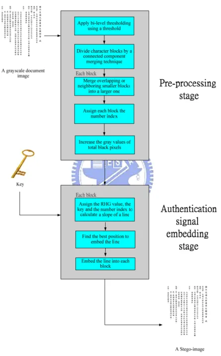
(18) 1.3.2 Brief Descriptions of Proposed Methods In this study, we focus on dealing with grayscale and binary document images. And for them, different watermarking algorithms will be proposed according to their different characteristics.. A.. Integrity Authentication Technique Surviving Print-And-Scan Attacks for Grayscale Document Images. A method for authentication of grayscale document images by a semi-fragile watermarking technique against print-and-scan attacks is proposed in this study, in which a line seen as a semi-fragile watermark and used as an authentication signal is embedded in a grayscale document image to create a stego-image. A rescanned image always has pixel-value distortion and geometric transformations, like scaling, slight rotation, and a little zero padding. Therefore, a watermark embedded in a rescanned image must be provided with robustness against pixel-value distortion and geometric operation attacks. In the proposed method, the block size used for embedding authentication signals is created by a region growing method. A line is produced by a key and adopted as an authentication signal, and is embedded in each block by modifying the gray value of the pixels. By choosing the least noticeable places in each block, the authentication signals can be embedded with less distortion. The authentication signals can be extracted from the stego-image by a line fitting technique. We then judge an image in suspicion as being tampered with or not by checking the difference between the embedded authentication signals and the extracted ones. Figure 1.1 shows a flowchart of the proposed method for embedding authentication signals in grayscale document images.. 5.
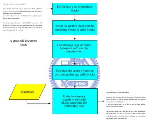
(19) Pre-processing. Pre-processing level. A grayscale document image. Each block Find the less perceivable place to embed the line. Key. Embedding authentication signals level. Embed a line into each block. A Stego-image. Figure 1.1 Flowchart of proposed method for embedding authentication signals in grayscale document images.. B.. Copyright Protection for Grayscale Document Images Using Edge Direction Histograms with Circular Interpretation. A method for copyright protection in grayscale document images using edge direction histograms with circular interpretation is proposed. We use the relationship between mother and child blocks to hide data. A mother block can be seen as a reference block. By modifying the gray value of the pixels in a child block, watermark signals can be embedded in it. More specifically, an edge direction histogram is 6.
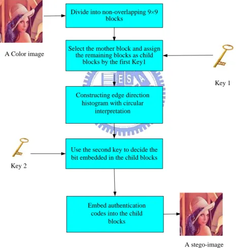
(20) created to collect all edge directions in a block to get a discrete distribution. Circular interpretation is then conducted to map an edge direction histogram into a circle. The center of mass in the edge direction histogram is calculated both in the mother and in the child blocks. By adjusting the location of the center of mass in an edge direction histogram circle of the child blocks according to the embedded data, the child blocks can carry the watermark signals. Figure 1.2 shows a flowchart of the proposed method for embedding watermark signals in grayscale document images. Divide into a set of primitive blocks. Select the mother block and the remaining blocks as child blocks. A grayscale document image. Constructing edge direction histogram with circular interpretation. Calculate the center of mass in both the mother and child blocks. Watermark Embed watermark signals in the child blocks according the embedding data. A stego-image. Figure 1.2 Flowchart of proposed method for embedding watermark signals in grayscale document images.. C.. A Fragile Authentication Method for Color Images. A method for image authentication in color images is proposed in this study. The block size used in the proposed method is chosen to be 3×3 as the mother block from a 9×9 block. The remaining blocks in the 9×9 block are regarded as child blocks. In. 7.
(21) the method, authentication signals and embedding locations are generated by two keys. The concept of edge direction histogram with circular interpretation is also used in this study. By modifying the location of the center of mass in the edge direction histogram circle of the child blocks, authentication codes can be embedded in them. We can then judge the stego-image in suspicion as being tampered with or not by checking the difference between the authentication codes and the extracted ones from the child blocks. Figure 1.3 shows a flowchart of the proposed method for embedding authentication signals method in color images. Divide into non-overlapping 9×9 blocks. A Color image. Select the mother block and assign the remaining blocks as child blocks by the first Key1 Key 1 Constructing edge direction histogram with circular interpretation. Use the second key to decide the bit embedded in the child blocks Key 2. Embed authentication codes into the child blocks. A stego-image. Figure 1.3 Flowchart of proposed method for embedding authentication signals in color images.. D.. Watermarking Method for Copyright Protection of Binary Document Images. 8.
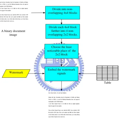
(22) In this topic, we focus on watermarking for binary document images. We choose the least noticeable 2×2 block from a 4×4 block to embed watermark signals. A reference table about how to embed data is created. With the help of the reference table, we embed data into a binary document image with less distortion. During the extraction process, the watermark signals can be extracted by table lookup from the reference table. Figure 1.4 shows a flowchart of the proposed method for embedding watermark signals in binary document images.. Divide into nonoverlapping 4x4 blocks. A binary document image. Divide each 4×4 block further into 4 nonoverlapping 2×2 blocks.. Choose the least noticeable place of the 2×2 block. Watermark. Embed the watermark signals Table. A Stego-image. Figure 1.4 Flowchart of proposed method for embedding watermark signals in binary document images.. E.. Hiding Digital Information And Authentication Signals behind Binary Images with Reduced Distortion And Enhanced Security. In this topic, a method for binary document images is proposed, which is based on Tseng and Tsai [1-2]. Because the method for embedding authentication signals in [1]. 9.
(23) and the method for embedding watermark signals in [2] use the same block size of 3×3, it is hoped to combine these two methods for embedding watermark and authentication signals together into a cover image, but this will cause some conflicts to occur. We propose a method to solve the conflict problem, in which, the block size for embedding authentication signals is modified to be 9×9, and the block size for embedding watermark signals is unchanged. We then embed watermark signals into the 3×3 blocks in a 9×9 block in which the authentication signals are embedded in advance.. 1.4 Contributions In this study, several contributions have been made, as described in the following. 1. A novel method is proposed to embed authentication signals against print-and-scan operations in grayscale document images.. 2. A method is proposed to embed watermark signals in grayscale document images.. 3. A method is proposed to embed authentication signals in color images.. 4. A method is proposed to embed data in binary document images.. 5. A method is proposed to integrate watermark and authentication signals for binary document images.. 1.5 Thesis Organization In the remainder of this study, the proposed method about authentication of grayscale document images against print-and-scan operations is described in Chapter 2. In Chapter 3, the proposed method for embedding watermark signals into grayscale document images is described. And in Chapter 4, the proposed method for embedding. 10.
(24) fragile authentication signals into color images is described. In Chapter 5, the proposed method for copyright protection by watermarking for binary document images is described. In Chapter 6, the proposed method to integrate watermark and authentication signals for binary document images is described. Finally, in Chapter 7, we will give some conclusions and briefly point out possible directions for future research works. In short, in Chapters 2 and 3, we deal with watermarking in grayscale document images, in Chapter 4, we deal with watermarking in color images, and finally, in Chapters 5 and 6, we deal with watermarking in binary document images.. 11.
(25) Chapter 2 Integrity Authentication of Grayscale Document Images Surviving Print-And-Scan Attacks In this chapter, a method for authentication of grayscale document images by a semi-fragile watermarking technique against print-and-scan attacks is proposed, in which a line seen as a semi-fragile watermark and used as an authentication signal is embedded in a grayscale document image to create a stego-image. During the authentication process, the authentication signals can be extracted by a line fitting technique to acquire the embedded line in each character of a stego-image in suspicion. The integrity of document images can be verified by comparing the difference between the embedded authentication signals and the extracted ones. The remainder of this chapter is organized as follows. In Section 2.1, an introduction is given first. In Section 2.2, the idea of the proposed method for authentication is briefly described. In Section 2.3, the process of embedding authentication signals is introduced. Section 2.4 includes a description of the process of extracting authentication signals. And in Section 2.5, some experimental results are given to show the feasibility of the proposed method. Finally, in Section 2.6, some discussions and a summary are made.. 2.1 Introduction 2.1.1 Problem Definition Because document images such as magazines and newspapers are widespread 12.
(26) and they are easy to duplicate or tamper with, the issues of copyright protection and authentication of document images must be taken into consideration more seriously. For instance, if a publisher publishes their magazines per month, they might want to design a scheme to protect their copyright and to authenticate the integrity of them. The definition of print-and-scan operation is to print an image and rescan it to become a digital version. Because of the rapid development of electronic products, printers and scanners are commonly used for distributions and reproductions of documents. It is popular to transform an image between the electronic digital format and the printed form. Some distortions may occur during the transformation; therefore, for copyright protection and integrity checking, it needs to design a scheme to solve this problem. It means that print-and-scan operations are regarded as normal behaviors to process an image, and they cannot be considered as tampering operations, but we still want to be sure whether the image resulting from rescanning is genuine in every part, i.e., to be sure the integrity of the image. So a developed scheme must have a certain degree of robustness against print-and-scan operations. Digital watermarking is a technique to embed a watermark into an image to protect the owner’s copyright of the image. And the watermark signals must be robust against print-and-scan operations. It is hoped that after applying these operations on the stego-image, the embedded watermark signals still can be detected and extracted exactly.. 2.1.2 Properties of Document Images Attacked by Print-And-Scan Operations If an image suffers from print and scan operations, there are two categories of distortions, namely geometric transformations and pixel value distortions. Geometric. 13.
(27) transformations include translation, rotation, cropping and scaling. And distortions of pixel values are caused by (1) luminance, contrast, gamma correction, and chrominance variations, and (2) blurring of neighboring pixels. These are typical effects of printers and scanners, and while they are perceived by human eyes, they affect the visual quality of a rescanned image [9]. Geometric transformations do not cause significant effects on the visual quality but the pixel value distortions do. Figure 2.1 shows an original image and a rescanned version of it. If we want to design a method for image authentication, embedding watermark signals is a way to achieve this goal. And the embedded authentication signal must have certain degrees of robustness against pixel-value distortions and geometric operations. In order to embed authentication signals in a grayscale document image against print-and-scan operations, invariant features of images with respect to geometric transformations should be adopted. Therefore, it’s better to use semi-fragile watermarks to embed authentication signals.. 2.1.3 Properties of Grayscale Document Images Document images are those coming from scanning printed or typewritten documents. A feature of document images is that there are many huge white blocks in background, so if we modify the gray values of pixels in the background, it is easy to be perceived. Another feature of document images is that it is usually text-dominated and reveals clear contrast between the background and the foreground. Because of pure color distribution, image processing on document images is easy to be noticed. A grayscale image has only one channel, the gray channel. Each pixel value of this channel is an integer between 0 and 255. In the proposed method, we focus on grayscale document images, and so how to embed data in the single channel of a. 14.
(28) grayscale document image is the main issue in this chapter.. (a). (b). (c). (d). Figure 2.1 A grayscale document image and a reproduced image. (a) A grayscale Chinese document image. (b) A grayscale English document image. (c) Reproduced image of (a) with quality of 100dpi. (d) Reproduced image of (b).. 15.
(29) 2.2 Idea of Proposed Authentication Method In the procedure of embedding authentication signals, a document image is first divided into non-overlapping blocks. Different processing an image in the unit of a constant block, we treat a character or a word as a basic block by a connected component merging technique. Second, to each word block, we assign a number index and then embed in it a line as a semi-fragile watermark by decreasing the gray values of these pixels in it. Coefficients of a line equation are created by (1) a secrete key, (2) an RHG value [10] which is used to assign a gray value G to a binary image block, and (3) the block number index, in order to enhance the security of authentication. As for the extraction of authentication signals, the pre-processing procedure of acquiring blocks is the same as the embedding one. And then we extract the least gray value of pixels in each block and apply a line fitting technique to obtain an equation of a line. In addition, we calculate another equation of a line by the key, the RHG value and the number index for each block. By comparing the difference between embedded line and calculated one in each block, we can verify the integrity of a grayscale document image.. 2.3 Authentication Signal Generation and Embedding In order to generate authentication signals for a grayscale document image, in our method, it is needed to do some pre-processing for the sake of reducing distortion. So there are two stages of tasks in our method, which are the pre-processing stage and the authentication signal embedding stage.. 16.
(30) 2.3.1 Pre-processing Stage A.. Bi-level thresholding:. The first step in the pre-processing stage is to remove noise and distortion. We apply a bi-level thresholding to increase the sensitivity of a region growing technique applied later. We set a threshold value to divide 256 pixel values into 2 pixel values, 0 and 255, and the corresponding pixels may be called black and white ones, respectively.. B.. Division of image into blocks by connected component merging:. If we process an image in terms of blocks of a fixed size, the blocks will be changed after the image suffers from scaling or shrinking. So, it is not suitable to utilize blocks of a fixed size to process an image against scaling. We utilize a technique of connected component merging or the so-called region growing in the data embedding and extraction processes to determine the size of a block, so the blocks defined in the data extraction and embedding processes have identical ranges. Region growing is a procedure that groups pixels or subregions into large regions based on predefined criteria. The basic concept is to start with a set of “seed” points and from them grow regions by appending to each seed those neighboring pixels that have properties similar to the seed [5]. Figure 2.2 shows an example of a character segmented as a basic block by the region growing method.. 17.
(31) (a). (b). (c). (d). Figure 2.2 An example of using region growing technique to get basic blocks. (a) Several Chinese characters. (b) Each character becomes a block (c) Several English characters. (d) Each character becomes a block. C.. Merging blocks: The objective of merging blocks is to merge overlapping or neighboring smaller. blocks into a larger one. If an image suffers from enlarging, gaps in characters will be enlarged. This means that a block may be divided into several parts and the total number of blocks after region growing will be different from the original one. So it is needed to devise a technique to solve this problem caused by image enlarging. We use a block merging technique to solve this problem. Two cases need be treated here. Case1: Several blocks are overlapping: If a block b1 and another block b2 are overlapping, then we merge the two blocks to establish a new one. Case2: Several blocks are neighboring: If the distance between the center of a block b1 and the center of another 18.
(32) block b2 are smaller than a threshold Ti, then we merge the two blocks into a new one. Figure 2.3 shows an example in this case. Figure 2.3 (a) is an image and its blocks acquired after region growing and (b) an image suffers from enlarging operations and its blocks acquired. As we can see, if an image suffers from scaling, the total number of blocks we obtain will be different from that of the original image. In Figure 2.3(c), c1, c2, c3 and c4 are the center of blocks 1, 2, 3, 4, respectively; d2, d3 and d4 are the distance between the center of the first block c1 and c2, c3 and c4, respectively. If d2, d3 or d4 are smaller then Ti, then we merge the two blocks. After merging blocks, the total number of blocks is identical to the original one. Figure 2.3 (d) shows an example after merging blocks. Figure 2.3(e) and (f) show another example of merging blocks.. (a) c1. (b). d4. d2. d3. c2. c3. c4. (c). (d). (e). (f). Figure 2.3 An example of block merging. (a) A Chinese document image and the total number of blocks is 2. (b) An enlarged image of (a) and the total number of blocks is 4. (c) Block distances of (b). (d) The result image of (b) after block merging. (e) An English document image and the total number of blocks is 12. (f) The result image of (e) after block merging.. 19.
(33) D.. Assignment of a number index to each block:. The reason of assigning each block a number index as a parameter to establish an equation of a line for embedding is to increase the security of authentication. In our method, after collecting all image blocks, we give a number index to each block. We do this for all blocks from the top-left to the bottom-right of the image.. E.. Increasing the gray values of total black pixels:. Because the equation of the embedded line in each block is to modify the gray values of the black pixels which the embedded line has passed through to 0, in order to distinguish the embedded black pixels from original black pixels, we need to increase the gray values of total black pixels to a threshold Ts.. 2.3.2 Creation and Embedding of Semi-Fragile Authentication Signals by Line Embedding The objective of the pre-processing stage is to decrease created distortions. In this section, we describe how to create and embed authentication signals into each block. The technique we describe below is the core skill. The main idea is to embed a value as a semi-fragile watermark into each block. And the value is the slope of a line. For the purpose of increasing the robustness, we will choose the best position to embed an authentication signal into each block. It seems a better choice to consider embedding data in black pixels in each block. After choosing the best position to hide an authentication signal in each block, we embed the slope of a line into each block by modifying the gray values of the black pixels through which the embedded line passes. The detail of semi-fragile watermark embedding is described below.. 20.
(34) A.. Acquiring the equation of the embedded line:. In order to enhance the security of authentication, we use a key, the RHG value and the block number index as parameters to build up the equation of the embedded line. An equation of a line is as follows: y = mx + b. (2.1). where x denotes a value of an x-coordinate, and y means similarly, m is a slope of a line, and b is a constant which means the shift of the y-axis. In our method, the slope of the line m is the main coefficient to control the slope of the embedded line. We create the value of m in terms of three elements: a key, the RHG value, and the block number index. After m is determined, b is used to adjust the shift of the embedded line to reduce the awareness by human eyes.. (1). A key:. A key held by the sender and the receiver is used to enhance the security of authentication as mentioned previously. It can be promised that even the algorithm is known by a thief, without a correct key he/she can not produce the authentication signals to cheat the algorithm during the authentication process.. (2). The RHG value:. The RHG value aims to assign a gray value G by the following reduced halftone gray function: G=. (T - B ) × level T. (2.2). where level means to divide total pixels into level parts, T is the total number of pixels and B is the number of black pixels. Equation (2.2) was proposed by Huang and Tsai 21.
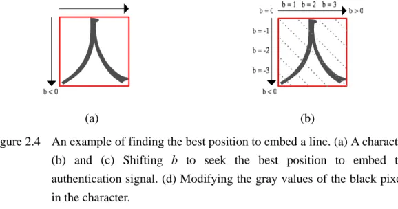
(35) [10]. Because the RHG is based on the use of blocks of a fixed size and can not be applied to our method directly, we revise it to meet our goal of allowing the use of arbitrary-sized blocks.. (3). The block number index. We assign each block a number index to represent it. The numbers are assigned in a raster scan order. The block number index is also a key parameter to build up the equation of a line. The reason is to avoid malicious attacks by altering the positions of blocks. After computing the three main elements, we compute the slope of the embedded line by the following equation: m = f(key, RHG value, block number index). (2.3). Because the size of a block is not infinite and the capacity to embed the slope m into each block is restricted, the slope m of the embedded line can not be too large. As a result, we need to limit the range of m. In our method, the function f is described as follows: m = (key+ RHG value + block number index )% range. (2.4). where range is used to control the range of m. By modifying the slope m of the embedded line, we can embed an authentication signal into each block.. B.. Finding the best position to embed a line. After calculating the slope of the embedded line, it is needed to find the best position to embed a line. A technique we use here is to adjust the constant value b of the equation of the line described in (2.1) to seek the best position to embed a line which arouses the least awareness. We shift the position of the embedded line by 22.
(36) modifying the constant value b. In our method, the black pixels with gray value Ts in each block are used to carry an authentication signal by modifying their gray values to 0. And the selection of black pixels for embedding an authentication signal is by checking whether the embedded line passes through. Because it is hoped that the authentication signal have a certain degree of robustness, we choose more places to embed it to increase the robustness. So, we find the position with the largest number of lining-up black pixels which the embedded line passes through to embed the authentication signal. The position of the most number of lining-up black pixels to embed the line is selected by modifying b and can be seen as the best position with the best robustness. Figure 2.4 shows an example of selecting the best position to embed a line. In this example we set m in Equation (2.1) to be m =1. Figure 2.4(a) shows a block after applying a region growing technique, and (b) is an example of shifting b to seek the best position to embed the line. After adjusting all possible values of b, we can find the best position to embed the line, as shown in Figure 2.4(c). Figure 2.4(d) shows that after selecting the value of b, we modify the gray values of the black pixels through which the embedded line passes in the block.. (a). (b). Figure 2.4 An example of finding the best position to embed a line. (a) A character. (b) and (c) Shifting b to seek the best position to embed the authentication signal. (d) Modifying the gray values of the black pixels in the character. 23.
(37) (c). (d). Figure 2.4 An example of finding the best position to embed a line. (a) A character. (b) and (c) Shifting b to seek the best position to embed the authentication signal. (d) Modifying the gray values of the black pixels in the character (continued).. C.. Embedding a line into each block. In order to increase the robustness, we select the best position to embed a semi-fragile watermark in each block. Because all the black pixels in a document image raise the gray values to Ts during the pre-processing stage, we can distinguish the authentication signal embedded in the black pixels in each block from the original black pixels by modifying the gray values of the black pixels which are selected for embedding the authentication signals. By decreasing to 0 the gray values of the black pixels through which the line has passed, we can embed a line into each block. So, during the authentication process, we only need to extract the least gray values of pixels in each block to recover the equation of the embedded line. Figure 2.5 shows an example of this step.. 24.
(38) Embedded line. (a). (b). Figure 2.5 An example of embedding a line into a block. (a) A block. (b) The result after embedding a line in (a).. 2.3.3 Detailed Algorithm The inputs to the proposed method for embedding authentication signals include a grayscale document image I and a key K. The output is a stego-image S. The algorithm for the process can be briefly expressed as follows. Figure 2.6 shows a flowchart of the process. Algorithm 1: Authentication signal embedding process. Input: A given grayscale document image I and a key K used in the authentication signal embedding process. Output: A stego image S. Steps: 1. Pre-Processing of a document image I: 1.1 Apply bi-level thresholding to I using a threshold Ti. 1.2 Divide I into character blocks by a connected component merging. 25.
(39) technique. 1.3 For each block Di, merge overlapping or neighboring smaller blocks into a larger one. 1.4 Assign each block Di a number index Si in a raster scan order from top left to bottom right. 1.5 Increase the gray values of all the black pixels in I to be Ts. 2. For each block Di, build up the equation of a line to be embedded. 2.1 Assign the RHG value according to (2.2). 2.2 Use K, Si and the RHG value to calculate a slope m of a line according to (2.3). 2.3 Find the best position to embed the line by shifting a constant of b. 2.4 Embed the line into Di by modifying the gray values of the black pixels through which the line passes.. 3. Take the final result as the desired stego-image S.. 2.4 Image Authentication process In the embedding process, the embedded authentication signal is the line created by the key, the RHG value, and the number index. Therefore, we can judge an image in suspicion as being tampered with or not by checking the difference of authentication signals between the generated slope m and the extracted slope m’.. 2.4.1 Extraction of Authentication Signals Using A Line Fitting Technique The proposed method for image authentication is essentially similar to the embedding one but in a reverse order. A suspicious image is first divided into non-overlapping. 26.
(40) blocks by a connect component merging technique, and then merging neighboring or overlapping smaller blocks into a larger one similar to the pre-processing of the embedding process. For each block, we collect the least gray values of the pixels and apply a line fitting technique to extract the authentication signals.. Figure 2.6 Flowchart of proposed method for authentication signal embedding in grayscale document images.. 27.
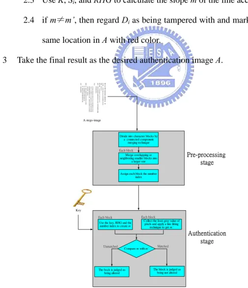
(41) A.. Applying a line fitting technique to extract the embedded line. During the embedding process, modifying to be 0 the gray values of the black. pixels which the line has passed through is the core technique to embed a semi-fragile watermark into each block. So, during the image authentication procedure, all we need to do is to collect the least gray values of the pixels in each block and extract the embedded line by a line fitting technique which is described as follows: n. m' =. n. n. n∑ xi yi −∑ xi ∑ yi i =1. i =1. n. i =1. n∑ x − (∑ xi ) i =1. (2.5). n. 2 i. 2. i =1. where m' means the slope of a line, n is the total number of pixels and X: [x1, x2, x3…xn]; Y: [y1, y2, y3…yn]. One thing needed to remind again is that b in (2.1) is only used for decreasing the awareness by human eyes and is irrelevant to the embedded authentication signals, so there is no need to calculate this constant.. We still have to collect three coefficients to get m according to (2.4) which are the key, RHG value, and the number index. By comparing the difference between m and m’, we can judge an image in suspicion as being tempered with or not in each block. Figure 2.7 is a flowchart of the proposed method for image authentication.. Algorithm 2: Image authentication process.. Input: A given stego-image S and the key K identical to that used in the embedding process. Output: An authentication image A. Steps: 1. Pre-Processing of a document image S. 28.
(42) 1.1 Divide S into character blocks by a connected component merging technique. 1.2 For each block Di, merge overlapping or neighboring smaller blocks into a larger one. 1.3 Assign each block Di a number index Si. 2. For each block Di, perform the following operations. 2.1 Collect the least gray values of pixels, and apply line fitting to the pixels to get m’ according to (2.5) 2.2 Assign the RHG value according to (2.2) 2.3 Use K, Si, and RHG to calculate the slope m of the line according to (2.4). 2.4 if m≠m’, then regard Di as being tampered with and mark the block at the same location in A with red color.. 3. Take the final result as the desired authentication image A.. A stego-image. Divide into character blocks by a connected component merging technique Each block Merge overlapping or neighboring smaller blocks into a larger one. Pre-processing stage. Assign each block the number index. Key Each block Use the key, RHG and the number index to create m. Each block Collect the least gray value of pixels and apply a line fitting technique to get m’. Authentication stage Unmatched. Compare m with m’. The bock is judged as being altered. Matched. The block is judged as being not altered. Figure 2.7 Flowchart of proposed method for image authentication. 29.
(43) 2.5 Experimental Results Some experimental results of applying the proposed method are shown here. Figure 2.8(a) and (b) are two grayscale Chinese and English document images, respectively, both with size of 400 × 500. And the stego-images resulting from embedding authentication signals are shown in Figure 2.8(c) and (d), respectively. Figure 2.8(e) and (f) are two stego-images suffering from print-and-scan operations, which were printed at 400dpi and scanned at 100dpi using an HP LaserJet 4200 printer and a MICROTEC Scanmaker 9800XL flatbed scanner. The corresponding PSNR values are shown in Table 2.1. Two tampered images suffering from print-and-scan operations are shown in Figure 2.9(a) and (b) with resolutions of 100dpi. And Figure 2.9(c) and (d) show the authentication results. The red parts indicate the detected tampered areas. By experiments, even if an image is subject to print-and-scan operations, we can still detect the integrity of a stego-image. The experimental results show that the embedded authentication signals have the semi-fragile property and can survive print-and-scan operations.. (a) Figure 2.8. (b). Input grayscale document images and output stego-images with authentication signals. (a) A grayscale Chinese document image. (b) A grayscale English document image. (c) and (d) stego-images after embedding. authentication. signals,. respectively.. stego-images suffer from print-and-scan operations. 30. (e). and. (f).
(44) (c). (d). (e). (f). Figure 2.8 Input grayscale document images and output stego-images with authentication signals. (a) A grayscale Chinese document image. (b) A grayscale English document image. (c) and (d) stego-images after embedding authentication signals, respectively. (e) and (f) stego-images suffer from print-and-scan operations (continued).. 31.
(45) Figure 2.9. (a). (b). (c). (d). Some tampered images and authentication results. (a) and (b) tampered images of Figures 2.8(e) and (f), respectively. (c) and (d) authentication results.. 32.
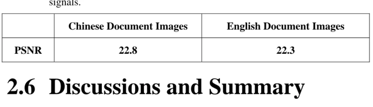
(46) Table 2.1 The PSNR values of the stego-images after embedding authentication signals. Chinese Document Images. English Document Images. 22.8. 22.3. PSNR. 2.6 Discussions and Summary In this chapter, we have presented an authentication scheme to embed authentication signals against print-and-scan operations in grayscale document images. The main idea of our method is to embed a line as a semi-fragile watermark into each block of a grayscale document image. And the equation of the embedded line is created by a key, an RHG value, and a block number index to increase the security of authentication. Because the line is embedded by modifying to 0 the gray values of the black pixels which the line has passed through during the image authentication process, we only need to collect the least gray values of the pixels in each block and apply a line fitting technique to extract the embedded line. We can verify the integrity of the image to be tampered with or not by comparing the difference between the generated slope m and the extracted slope m’. If someone tampers with a stego-image, the RHG value or the block number index will be changed. The extracted slope m’ of the embedded line from the tampered image will then not be the same as the generated slope m. Therefore, the tampered areas can be detected and located. In our method, we use a linear equation of the first order to embed an authentication signal; we also can use a polynomial equation in the same way to increase the security. It is common to print document files. And the print-and-scan operation should not be considered as a tampering operation, though it is a huge attack so far as the 33.
(47) resulting image quality is concerned. The experimental results prove our proposed method to be useful and that the embedded authentication signals can survive print-and-scan operations.. 34.
(48) Chapter 3 Copyright Protection for Grayscale Document Images Using Edge Direction Histograms with Circular Interpretation The proposed method for copyright protection of grayscale document images is described in this chapter. The main idea is based on two techniques, namely, edge direction histograms (EDH) and circular interpretation, and we will describe these two terms later. These techniques are employed to embed watermark signals into grayscale document images. The reminder of this chapter is organized as follows. In Section 3.1, an introduction and the term definitions are first given. The idea of the proposed watermarking method is presented in Section 3.2. The watermark embedding process and the watermark extraction process are shown in Section 3.3 and Section 3.4, respectively. In Section 3.5, several experimental results are illustrated. Finally, in Section 3.5, some discussions and a summary are made.. 3.1 Introduction Digital watermarking is a technique for embedding a watermark into an image to protect the owner’s copyright of the image. However, the stego-images are easy to be modified, thus destroying the watermark signals. As a result, the stego-images need to be robust to avoid malicious attacks. There are many existing robust methods to embed watermark signals into an image, but the capacity offered by each of these. 35.
(49) methods is relative small. We all know that this involves a tradeoff problem. When the robustness is increased, the capacity is decreased. In this study, we aim at making a compromise between the capacity and the robustness for grayscale document images.. 3.1.1 Motivation Because digital text document files such as e-books and digital library files are spread easily and gained popularity, and because they are easy to duplicate or tamper with, how to protect these precious files is a main concern in recent years. A watermark scheme is a way to achieve this goal to protect the copyright of these documents. In our method, we deal with grayscale document images which come from scanning printed or typewritten documents. And it is hoped that the embedded watermark signals have a certain degree of robustness for copyright protection and can survived attacks like sharpening or blurring. In the meantime, it is desired that the capacity to embed a watermark can not be too small.. 3.1.2 Problem Definition The properties of grayscale document images are described in Section 2.1.2. In short, a document image is usually text-dominated and reveals clear contrast between the background and the foreground. And a text document image has a hierarchical structure: a page image can be successively decomposed into blocks, lines, words, characters, strokes, and pixels [3]. In this chapter, we describe a method to embed a robust watermark with less distortion into a document image for copyright protection. We use a technique based on the use of the edge directional histogram with circular interpretation to embed the watermark signals. The algorithm is based on the fact that texts have similar shapes in. 36.
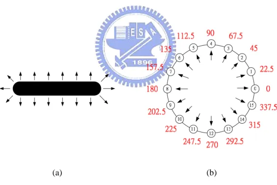
(50) their edge direction histograms [3] which will be described later, and that texts appears widely in document images.. 3.1.3 Definition of Edge Direction Histograms An edge direction histogram (EDH) collects all edge directions in a block and shows a discrete distribution. Edge direction values may be computed by the Sobel edge operator [4]. After applying the Sobel edge operator to a grayscale document image, a watermark can be embedded in a block utilizing the resulting edge values, as described in Kim and Oh [3]. In our method, first we apply the Sobel operator to get an edge direction image and then quantize it into 16 levels. We then quantize the directions into 16 codes. Figure 3.1 shows the encoding of edge directions. More specifically, we acquire edge directions by the Sobel x-mask and y-mask to get the edge values of the x and y directions, respectively, and then apply the arc tangent operator to obtain the degree values of the directions. Finally, we quantize the degree values into 16 levels. Figure 3.2 is an example of edge direction value computation. Figure 3.2(a) shows the gray values of pixels in a 3×3 block, (b) and (c) are the Sobel masks Gx and Gy of the x-direction and the y-direction, respectively. Figure 3.2(d) and (e) are the results of (a) after applying the Sobel x and y masks. Figure 3.2(f) is an edge direction image which is created by the following formula: Gd = tan-1(Gy/Gx).. (3.1). Because the range of arc tangent is from -90° ~ +90°, it is necessary to modify the degree of arc-tangent to be from 0° to 360° as shown in Figure 3.2(f). Finally, Figure 3.2(g) shows the result of (f) after quantizing the edge direction values into 16 levels. An EDH with direction levels in the range [0, 15] is a discrete function H(rk)=nk, where rk is the kth edge direction level and nk is the number of edge directions after. 37.
(51) applying the Sobel masks. Like the definition of histogram, an EDH also needs to be normalized by dividing each of its values by the total number of edge directions, denoted by sum. As a result, a normalized EDH is given by p(rk)=nk/sum, for k = 0, 1, …, 15, where p(rk) are an estimate of the probability of edge direction level rk. The sum of all the components of the normalized EDH is equal to 1. Different from the general definition of histogram, because we can apply the Sobel operator to each block to get an edge direction histogram, there are many edge direction histograms in an image.. (a). (b). Figure 3.1 Encoding of edge direction. (a) Edge direction. (b) Edge direction. quantized into 16 levels.. 38.
(52) 70. 0. 0. 0. 0. -1. 71. 81. 78. 75. 74. -2. 72. 78. 79. 71. 74. -1. 70. 83. 77. 73. 71. 0 0. 1. 1. 2. 0. 1. -1. 2. 0 -2. Gx. (a). 1 -1. Gy. (b). (c). 81. -133. -6. -4. -75. -223 -311 -312 -302 -223. 240. -49. -19. -13. -221. -82. 320. 28. -30. -20. -290. 0. -2. 2. 8. 8. 244. 21. -27. -17. -217. 222. 307. 307. 295. 219. -237 -307 -295 -219. Gx(2,2)= 70*-1+71*-2+72*1+0*1+78*2+79*1=-49. Gy(2,2)=70*1+0*2+0*172*1-78*2-79*1=-237. (d). (e). 290. 246.8 268.9 269.2 251.4. 13. 11. 12. 12. 11. 15. 11. 12. 12. 10. 0. 0. 8. 7. 8. 2. 4. 4. 4. 6. 341.1 258.3 266.5 267.5 224.7 0 42.3. 355.9 176.2 158.2 178.4 86.1. 95. 93.3. 134.7. Edge Direction Gd(2,2)=tan(Gy/Gx)= 78.3. Quantized Directions. Gd(2,2)+180= 258.3 (f). (g). Figure 3.2 An example of edge direction value computation. (a) Several pixels. (b) The x-direction Sobel mask Gx.(c) The y-direction Sobel mask Gy. (d) and (e) The result of (a) after applying Gx and Gy mask, respectively. (f) Edge direction using (3.1). (g) The result after quantizing the edge direction of (f) into 16 levels. 39.
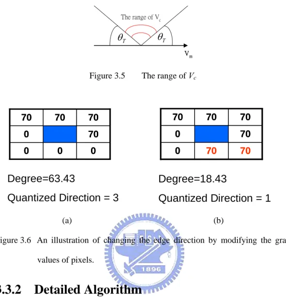
(53) 3.1.4 Definition of Circular Interpretation The meaning of circular interpretation is to map a histogram into a circle [6]. In our method, an edge direction histogram with circular interpretation means to map an EDH to a circle, which is called EDH circle. The position of an EDH value on the circle is a weight proportional to the occurrence of the edge strength. The position of the center of mass in the EDH circle is the result of the weight distribution, as shown in Figure 3.3(b) where C1 is the center of the mass of the circle. Figure 3.3 shows an example of circular interpretation and the center of mass in the EDH circle.. Edge Direction Histogram 160 140. Edge Strength. Sum. 120 100 80 60 40 20 0 0. 1. 2. 3. 4. 5. 6. 7. 8. 9. 10. 11 12. 13 14 15. Edge Level. (a). (b). Figure 3.3 The edge direction histogram mapped into a circle. (a) Edge direction histogram. (b) A circle mapped by (a).. 3.2 Idea of Watermark Embedding Method The proposed watermark embedding method is based on a pixel-level watermarking algorithm for grayscale document images. It means that a watermark can be embedded by modifying the gray values of pixels. Instead of adopting the way. 40.
數據

+7
相關文件
This document uses the terminology defined in the UPnP Architecture document, such as: action, SST variable, and action parameter. This sub-section defines the following
In Chapter 2, this research first briefly introduces different kinds of international classifications of service trade, and then presents the definitions of service industries
Starting from a discussion on this chapter, Jay a nanda proceeds to explain 22 kinds of mental initiation for the pursuit of enlightenment... The first chapter of Madhyamak a vat a
This theorem does not establish the existence of a consis- tent estimator sequence since, with the true value θ 0 unknown, the data do not tell us which root to choose so as to obtain
These types of attacks are what we call algebraic replay attacks targeting the challenge- response mechanism in authentication protocols, attribute acquisition attacks on
Teachers may consider the school’s aims and conditions or even the language environment to select the most appropriate approach according to students’ need and ability; or develop
Chen, The semismooth-related properties of a merit function and a descent method for the nonlinear complementarity problem, Journal of Global Optimization, vol.. Soares, A new
See Chapter 5, Interrupt and Exception Handling, in the IA-32 Intel Architecture Software Developer’s Manual, Volume 3, for a detailed description of the processor’s mechanism
