IEEE JOURNAL OF OCEANIC ENGINEERING, VOL. 21, NO. 1, JANUARY 1996
Programmable
S
witched-Capacitor Neural
Network for
MVDR
Beamforming
Wen-Hao Yang and Po-Rong Chang, Member, IEEE
Abstruct- In this paper, a real-time adaptive antenna ar- ray based on a neural network approach is presented. Since an array operating in a nonstationary environment requires a programmable synaptic weight matrix for the neural network, the switched-capacitor (SC) circuits with the capability of pro- grammability and reconfigurability is conducted to implement the neural-based adaptive array. Moreover, the SC techniques can directly implement the neural network with less chip area and provide the ratio of SC-equivalent resistors with accuracy of 0.1 percent. Programming of the switched-capacitor values could be made by allocating each synaptic weight to a set of parallel capacitors with values in a digitally programmable capacitor array (PCA). A relatively wide range of values (5 to 10 binary bits resolution) can be realized for each synaptic weight. A simulation tool called SWITCAP is used to verify the validity and performance of the proposed implementation. Experimental results show that the computation time of solving a linear array of 5 elements is about 0.1 ns for 1 ns time constant and is independent of signal power levels.
I. INTRODUCTION
HE purpose of adaptive arrays is to suppress unwanted
T
jamming interferences and to produce the optimal beam- former response which contains minimal contributions due to noise. The most commonly employed technique for deriving the adaptive weights uses a closed-loop gradient descent algorithm where the weight updates are derived from estimates of the correlation between the signal in each channel and the summed output of the array [l], [2]. The fundamental limitation for this technique is one of poor convergence for a broad dynamic range signal environment. Several differ- ent approaches for choosing optimum beamformer weights are summarized in [3]. In many applications, none of those approaches is satisfactory. The desired signal may be of unknown strength and may always be present, resulting in signal cancellation with the multiple sidelobe canceller and preventing estimation of signal and noise covariance matrices in the maximum SNR processor. These limitations can be overcome through the application of linear constraints to the weights. The basic concept of linearly constrained minimum variance (LCMV) beamforming is to constrain the response of the beamformer such that the desired signals are passed with specified gain and phase. The weights are chosen to minimize output power subject to the response constraint. When the beamformer has unity response in the look direction, the LCMV problem would become the minimum variance supported in part by the National Science Council, Republic of China. National Chiao Tung University, Hsinchu, Taiwan, R.O.C.Manuscript received March 1, 1995; revised July 30, 1995. This work was The authors are with the Department of Communication Engineering, mtblisher Item Identifier S 0364-9059(96)00795-9.
distortionless response (MVDR) beamformer problem which is a very general approach employed to control beamformer output.
The complex weights of an MVDR-based beamformer should be updated in real time in order to respond to the rapid time-varying environment. Meanwhile, the calculation of weights is computationally intensive and can hardly meet the real-time requirement. Systolic implementations of optimum beamformers have been studied to improve the computational speed by a number of investigators [4], [5]. As an alternative to the digital approach, an analog approach based on Hopfield- type neural networks could operate at much higher speed and requires less hardware than digital implementation.
Recently, Tank and Hopfield [6] have shown how a set of neural networks with symmetric connections between neu- rons presents a dynamics that leads to the optimization of a quadratic functional. Most recently, Chua and Lin [7] and Kennedy and Chua [SI, [9] extended the design of Hopfield network and introduced a canonical nonlinear programming circuit which is able to handle more general optimization prob- lems. They showed that a canonical neural network assigned to solve the optimization problem would reach a solution in a time determined by RC time constant, not by algorithmic time complexity. Therefore, the convergence speed of reaching the optimal solution is dramatically improved. Chang, Yang, and Chan [lo] showed that an MVDR-based neural analog circuit is able to quickly attain its optimal performance, and works sat- isfactorily under the stringent environment of strong jammers. The primary concern of the neural circuit using R C design is that an array operating in a nonstationary environment requires a programmable synaptic weight matrix for the neural network. The RC-active design is not the best suited for monolithic implementation, especially taking into account that accurate and wide dynamic range resistors and large R C values are required. In this paper, we try to overcome this drawback by focusing on the design of implementing the MVDR beamform- ing neural network using switched-capacitor techniques. The inherent programmability and reconfigurability of switched- capacitor circuits together with the maturity of this technique
[12] in the field of analog VLSI would be conducted to improve the conditional design. We use the dynamically and digitally programmable capacitor array (PCA’s) [ 111, [ 131 to realize the time-varying synaptic weight matrix on a real-time
basis. Moreover, a relatively wide range of values (5 to 10
binary bits resolution) can be realized for each synaptic weight. In this paper, we first introduce the real-valued quadratic op- timization problem derived from MVDR beamforming prob- lem. Moreover, a discrete-time neural circuit dynamic equation 03649059/96$05.00 0 1996 IEEE
78 IEEE JOURNAL OF OCEANIC ENGINEERING, VOL. 21, NO. 1, JANUARY 1996
for the quadratic optimization is established. In Section IV, we propose a switched-capacitor realization for implementing the system dynamics. In addition, the programmable capacitor ar- ray (PCA) is introduced to match the time-varying covariance matrix of the adaptive antenna array. Experimental results are shown in Section V, and conclusions are given in the last section.
11. PROBLEM FORMLJLATTON
For a linear array composed of L isotropic antenna elements which receive narrow-band signals from sources of variation frequency f o located far from the array,
~ ( t )
is defined as a complex output of the Zth element at the sampling time t , and can be expressed as(1)
Q ( t )
= m(t)e32nfo(t+7.1(er~))+
nl(t)+
X I I ( t ) whereI
is the time delay of the Zth element relative to a reference point chosen at origin. T L is the position vector of the Zth element. s ( 6 ,
4)
is a unit vector in the direction ( 6 ,4)
of the source, and c is the propagation speed of the plane wave in free space. The source amplitude m(t) is characterized statistically byE [ m ( t ) ] = 0
(3)
E[m(t)m*(t)] = P s (4)
where
E[.]
is the expectation operator, p s is the power of the source, and * denotes the complex conjugate. x:n(t) is the component of the directional interferences received by the Zthelement and possesses the same statistics as the source. In addition, nl(t) is a white random noise with properties
( 5 ) E [ n l ( t ) n z ( t ) ] C T ; ~ L ~ , I , k = 1, 2,
.. . ,
L. (6)E[nl(t)] = 0 , 1 = 1, 2 , .
. .
,
LLet the signal waveforms derived from the L elements of
a beamformer be represented by an L-dimensional complex vector
(7) def
x = [XI, 5 2 , " . , % L I T
and the weights of element outputs be represented by L- dimensional complex vector w ,
(8) def
w = [ W l , w2,.
. .
,
W L ] Twhere T denotes the transpose of the vector. Then the output
of the beamformer can be written as
L
y ( t ) = W l " 5 l ( t ) = w H z ( t ) (9) l=1
where H denotes the complex conjugate transpose of a vector. Since each component of
~ ( t )
is modeled as a zero mean stationary process, the mean output power of the beamformer is given byP ( W ) = E[Y(t)Y*(t)l
= w H R w (10)
where R is the array correlation matrix.
In
order to achieve the optimal utilization of the mean output power of the beamformer, the weights are chosen based on the statistics of the data received at the array such that the output contains minimal influence due to noise as well as interference signals arriving from other directions. Different criteria exist for choosing optimum beamformer weights, which are summarized in [3]. A general approach called minimum variance distortionless response (MVDR) beamfoming is to constrain the response of the beamformerso that the desired signals are passed with unit gain and the weights are chosen to minimize the output power subject to the required constraints. The MVDR beamforming problem is usually formulated as
Min $ ( w ) = w H R w (11)
W
Subject to wHs0 = 1 (12)
where SO is the steering vector associated with the look
direction and is given by
(13) where d is the element spacing, A0 the wavelength of the plane wave in free space, and 60 the look direction angle (the angle between the axis of the linear array and the direction of the desired signal source).
The method of Lagrange multipliers can be used to solve (1 1) and (12) and resulting in
Note that, in practice, the presence of uncorrelated noise ensures that R is invertible.
The MVDR beamforming problem defined in both (1 1) and (12) is indeed a complex-value constrained quadratic program- ming problem, which cannot be solved by neural network directly.
In
order to meet the requirement of neural-based optimizer, one should convert it into a real-value constrained quadratic programming formulation. Since R is a positive- definite Hermitian matrix, it has been shown [lo] that the above complex-valued MVDR beamforming problem can be transformed to be a real canonical quadratic nonlinear pro- gramming problem with linear equality constraints as follows.1
U 2
Min $ ( U ) = -vxGv (15)
Subject to f(u) =
Bv
- e = 0 (16) where is a 2L-dimensional real weight vector, G is a (2L) x (2L) symmetric, positive-definite matrix, and f ( v ) is the constraint column vector. B and e are 2 x (2 L) matrix and (2 x 1) column vector. They are defined as follows:-
YANG AND CHANG PROGRAMMABLE SWITCHED-CAPACITOR NEURAL NETWORK FOR MVDR BEAMFORMING 19
and
2Rr -2l&
G = [ 2 , 2RJ
e =
[;I
where wr,
a,
sor and wi, Ri, SO^ are the real parts and imaginary parts of w, R, and SO, respectively.111. A HOPFIELD NEURAL NETWORK APPROACH
TO THE MVDR BEAMFORMING PRoBLEM
To solve the constrained nonlinear programming problem defined in (15) and (16), we convert it to an equivalent unconstrained problem. The way to do this is to define a pseudo-cost function E ( v ) as follows:
(21)
where
4(v)
is the original cost function, P(u) is referred to as the penalty function, and cx and p are called the acceleration factor and the penalty multiplier, respectively.A valid penalty function must monotonically increase as the constraints fj(v)’s deviate from the feasible region, which is the subspace of the multidimensional space defined by con- straints. In general, the absolute value or the square operator fulfills this requisite. In this paper, the square operator is employed and the penalty function is defined by
E(w) = 4 ( V )
+
PP(’U)It is interesting to note that the pseudo-cost function E(w) can be identified as energy function of the circuit with the system of equations [lo]
(23) dv dt
c-
= -VE(w),c
>
0 or where i, = f J ( w ) .The equilibrium point of the gradient system coincides with either a local extreme (minimum or maximum) or inflection point of E(w). However, since C
>
0, the time evolution of v will result in E ( v ) decreased monotonically. Therefore, the circuit would seek a local minimum of the pseudo-cost function E(w). Since the Hessian matrix of E(w) is positive definite throughout the feasible region, it is shown in [14] that any local minimum of E ( v ) is a global minimum over this feasible region. As a result, the circuit solution tends to a global minimum of the original cost function +(w) when dE/dt = 0.The MVDR-based neural network would include two partic- ular modules. The first module is called the variable amplifier, which can perform the integral of a sum of input currents
( - a d $ / d v k ) and (-Pi,dfj/dVk), and then produces the
(b) Fig. 1.
fier, (b) constraint amplifier.
Basic blocks of neural circuit using RC-design: (a) variable ampli-
desired output variable V k . Fig. l(a) shows the circuit imple-
mentation of the variable amplifier consisting of an integrator and a unity gain inverting amplifier. The inverting amplifier can provide an output of the variable - V k which is required for the circuit implementation of negative weights. The second module is called the constraint amplifier, which is used to perform the constraint satisfaction function f j (.). The circuit
realization is shown in Fig. l(b). Without loss of generality, the penalty multiplier ,u may be included in g,(-). Thus, the circuit yields the input-output relation: 0 =
-PI,
where prepresents the magnitude of the resistance, and 0 and I are an output voltage and an input current, respectively. If the input current I is equal to - f j ( v ) , then 0 = - p ( - f j ( w ) ) =
Looking upon the circuit system dynamics of (24), the controlled current source d $ / d V k and conductance d f j /dvk are given by
P f m = S j ( f , ( V ) ) = ij.
where gki and b j k are the ( k , i ) and ( j , k ) entries of G and
B , respectively.
Equation (25) shows that the input current d+/dvl, is a linear sum of the vi’s weighted by conductances s k i ’ s . In the case of linear constraints, the weights df,(u)/dvk are con- stants, and so may be implemented directly as conductances. Combining (24)-(26), one would obtain the state equations to the circuit implementation as
80 IEEE JOURNAL OF OCEANIC ENGINEERING, VOL. 21, NO. 1, JANUARY 1996
i-
Fig. 2.
problem using RC-design.
Schematic diagram of neural circuit for MVDR-based beamfoming
and
2L 2
-
- - c g ; 2 v z - Ci,b,k. (28)
Note that the acceleration factor a is included in g k 2 ' s , and then g i z is defined as ( a g k 2 ) .
According to (27) and (28), a circuit realization is shown in Fig. 2. It should be noted that the elements of the e, G', and B matrices are realized directly as resistive connections, and that. their associated matrix entries correspond to conductance values.
2 = 1 ,=1
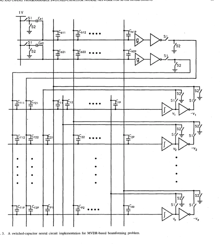
I v . SWITCHED-CAPACITOR REALIZATION FOR NEURAL-BASED MVDR BEAMFORMING In the realization of the Tank and Hopfield neural network [6], they use the conventional RC-active design techniques. The main drawbacks arise for accurate resistors and large RC values which are required for RC-active design. This implies that RC-active design is not the best suited for monolithic implementation. In this paper, we try to overcome this drawback by focusing on the design of implementing the MVDR-based neural network using switched-capacitor tech- niques. The inherent programmability and reconfigurability of switched-capacitor circuits together with the maturity of this technique [12], [13] in the field of analog VLSI would be conducted to improve the performance of conventional design. The switched-capacitor implementation (as shown in Fig. 3) is obtained by replacing the basic switched-capacitor modules
into the RC-based neural Gircuit architecture in Fig. 2. The details about the schematic realization of each basic module will be discussed in the following.
A. A Mapping Between Resistor and Switched-Capacitor Neural Network
In order to implement the MVDR-based neural network using switched-capacitor circuits, the circuit equations of (28)
should be discretized by the forward-Euler formula, and are given by
I
2 ' u Z ( R .+
1) = vz(n> -Cd,.,(.)
+
/LCb,Zf,(~)
> ,=1 i = 1, 2 , . . . , 2 L (29)[:Il
where u,(n) = ~ * ( t ) l t = ~ ~ , and
2L
fj(n) = f,@)It=nT = C b , 2 v 2 ( n ) - e, (30)
and T denotes the period of the clocks which control the switches.
According to (29) and (30), Fig. 3 shows the schematic realization of switched-capacitor implementation for MVDR- based nonlinear programming problem. The SC circuit is on basis of theRC-active circuit architecture shown in Fig. 2 whose resistive elements are instead of capacitors and switches. Moreover, the details of the proposed SC circuit would be discussed in Subsection B.
Basicdly, the general SC circuit is composed of capac- itors, op amps, and switches. The switches are controlled by two nonoverlapping clock phases S1 and S2. As shown in Fig. 3, there are three basic modules involved in the SC implementation. They are integrator, inverter, and summer. The schematic realization of each basic module' would be discussed as follows.
1 ) Switched-Capacitor Integrator: The parasitic-insensi- tive SC integrator (variable amplifier) with multiple inputs is shown in Fig. 4(a). For the sake of describing the function of the circuit briefly, we consider a single-input SC integrator first. During the nth clock phase S1, the input capacitor C1
is charged to the input voltage v l ( n ) , while the integrator capacitor Cf is held at v g ( n - 1). When C1 is grounded
during the clock phase S2, the charge Clvl(n) from C1 will be eansfened to the capacitor C f . The ideal output voltage vo(n) during clock phase S2 is
2 = 1
(31) The voltage across the auxiliary hold capacitor Ch com- pensates the offset voltage and dc gain error of the op amp. The recursive realization of (3 1) results in the first-order approximation to the integrator
C1 Cf vo(n) = vo(n - 1)
+
--.I(.).YANG AND CHANG PROGRAMMABLE SWITCHED-CAPACITOR NEURAL NETWORK FOR MVDR BEAMFORMING
I V
Fig. 3. A switched-capacitor neural circuit implementation for MVDR-based beamforming problem.
Similarly, the output voltage of multiple-input integrator shown in Fig. 4(a) during clock phase S2 is characterized by
voltage
c,
(33) vo(n) = --v,(n).
Cf
ca
a = 1 Cf vo(n) = vo(n
-
1)+
C-.i(n).
81
(34)
2 ) Switched-Capacitor Znverter and Summer: Since the negative weights are required in the beamforming problem, an SC inverter is used to achieve the negative terminal of the neuron’s output voltage instead of the negative weights. From a precision SC inverter shown in Fig. 4(b), during the nth clock phase S1, the input capacitor Ci is charged to v,(n), and then the output voltage becomes a scaled value of input
At the mean time, the hold capacitor Ch is charged to vo(n), while the output voltage of the inverter is kept at constant value during the full nth clock period. During the clock phase S2,
the charges at both C, and C f are discharged to suppress the offset voltage of the op amp. This also reduces the possibility of the accumulated error due to the residued charges at Ca and C f .
82
sz
nT (n+l)T
IEEE JOURNAL OF OCEANIC ENGINEERING, VOL. 21, NO. 1, JANUARY 1996
r - - - ;
\ 2i-1 C O --
(C) ( 4 Fig. 4.a parasitic-insensitive summer; (d) digitally programmable capacitor array @CA) and simplified notation.
The required clock signals and basic switched-capacitor blocks: (a) a parasitic-insensitive integrator (neuron); (b) a parasitic-insensitive inverter; (c)
The schematics of a multiple-input SC inverting summer is shown in Fig. 4(c). The inverting summer produces an output voltage uug(n) at the nth clock period by
(35) 3 ) Programmable Capacitor Array: Since the synaptic weight matrix for the MVDR-based neural network should be programmable when the array operates in a nonstationary environment, this subsection presents digitally programmable capacitor arrays (PCA's) which can be programmed on
a real-time basis. The PCA's can be realized using a number of binary weighted capacitors. Fig. 4(d) shows several capacitors (CI
,
Cz,
. . .
,
C N ) , each connected by a series switch(SI,
S2, .. .
,
SN)
to a common node. The digital control word ( b l,
b 2 ,. .
.,
b N ) determines whether an individual capacitor is connected with or disconnected from the circuit. If the bit b, has the logical value 1, then the switch S, on the capacitor C, is connected between nodes x andy. Usually, the capacitances are weighted by powers of two (i.e., C1 = C O , Cz = ~ C O , . . . ,C, = aN-'Cug). It should be noted that the capacitor never floats, and the total capacitance loading node y is constant. The value of the capacitance
YANG AND CHANG: PROGRAMMABLE SWITCHED-CAPACITOR NEURAL NETWORK FOR MVDR BEAMFORMING 83
between x and y in the N-bit PCA is given by
N N
Ct = C b i C i = CoC2i-1bi (36) where CO is the capacitance basis of PCA, and the practical value of N can be up to ten.
i=l a = 1
B. Determination of the Capacitance Values in SC Neural Networks
In this subsection, it is desired to design the MVDR-based neural circuit on the basis of the above-mentioned SC modules. The proposed SC neural network for MVDR beamforming is shown in Fig. 3. Next, we would like to validate our circuit which can exactly implement MVDR-based neural network. During the nth clock phase S1, the inverted outputs of the variable amplifiers (neurons), vi(n)'s, are sent to the inputs of the constraint summers with associated weights. Thus, the j t h summer's output is given by
where the capacitances C,, and c b 3 a are connected to the
constant voltage source 1 V and the output terminal of the ith variable amplifier, respectively. Note that C f is a constant capacitance of constraint amplifier.
Comparing (30) and (37), it can be shown that both equa- tions become identical when b,, = (cbjz/cf) and e3 =
( C e , / C f ) . During the clock phase S2, the charges at both capacitors, C f J a ' s and C2j's, are transferred to the capacitor C f of the ith neuron or variable integrator amplifier. Since
C,, and C f J a are connected to the output terminal of the ith variable amplifier and the output of the jth constraint amplifier, respectively, the current flowing into the ith variable amplifier is obtained by
The ideal output of the ith variable amplifier is the inte- gral of the input current during clock phase S2. During the nth clock phase S1, the transferred charge and incremental output voltage can be obtained according to the law of the conservation of charges and are given by
rp
(39)
Thus, the output voltage at ( n
+
1)th clock phase becomesVi(.
+
1) = Vi(.)+
- I . ( n ) -Cf [ a
:]
Comparing (29) and (41), it is found that the proposed SC circuit can implement the MVDR-based neural network when the following conditions are satisfied, i.e.:
Notice that the negative values of both capacitance ratios represent the connection to the negative output terminal of the variable amplifier. From (25) and (26), it can be shown that gij and b j i are dependent on the elements of the array
correlation matrix and the steering vector, respectively. How- ever, these parameters are not fixed when the array operates in a nonstationary environment. It requires the programming of their corresponding capacitance ratio values according to (42). Programming of the switched-capacitor ratio values could be made by allocating appropriate values to a set of parallel capacitors with values in PCA.
V. ILLUSTRATED EXAMPLES
To verify the effectiveness of MVDR-based switched- capacitor neural circuit implementation, a linear array of five elements with half-wavelength spacing is considered in the following example. The variance of white noise present in each element is assumed to be equal to 0.1. In addition, there are two interference sources which fall in the mainlobe and the peak of the first sidelobe of the conventional uniform array pattern, respectively. The first interference makes an angle 55'
(191 = 55') with the line of the array and has the power which
is taken to be 20 dB above the white noise power. The second interference makes an angle of 110" ( 0 2 = 110") and has the
power which is 10 dB more than the white noise power. The look direction of the signal is assumed to be orthogonal to the array. In our example, two signal power levels, 1 dB and 10 dB, are employed in the simulation.
The simulation of the MVDR-based switched-capacitor neu- ral circuit is performed using the SWITCAP, which is a general simulation program for analyzing a switched-capacitor network [15]. The dynamics of the neural circuit is described by (29) and (30). The switching clock period is s.
The capacitance C related to each variable amplifier of the RC circuit and the capacitance C f of the switched-capacitor integrator are taken to be of the same value 1 pF. In addition, the penalty multiplier p in each constraint amplifier and the acceleration factor Q: are taken to be 2 and 0.002, respectively.
Fig. 5 shows the transient response of two output S N R s
corresponding to their signal power levels 1 and 10 dB, respectively. It is noted that the converge time of each curve in Fig. 5 is almost independent of p , and equals 0.1 ns. Reference [lo] showed that the converge time is characterized by the system time constant of the circuit. The comparisons of power patterns of a conventional uniform array and the resulting neural-based adaptive array are given in Fig. 6. It is observed that two sharp nulls presented in the pattern correspond to the directions of the interference sources, i.e., 55" and 110'. Furthermore, it should be mentioned that the values of capacitors Caj's and C f J a 7 s are dependent on the signal power level p , and its look direction, respectively. For example,
84 IEEE JOURNAL OF OCEANIC ENGINEERING, VOL. 21, NO. 1, JANUARY 1996 1-- --- 100
P
10 10 SE011 1E-010 15E-010 2E-010 25E-010 3Ed10 35E-010 Time(ser)
Fig. 5 .
array.
The output SNR versus the response time for a five-element linear
100 10” 104 0 20 40 60 80 100 120 140 160 180 Deg. Fig. 6.
array and neural-based array.
Comparison of power patterns achieved by the conventional uniform
C15 (or C ~ I ) corresponding to their associated signal power levels 1 and 10 dB are 0.00265 and 0.00625, respectiveIy. Fortunately, the adjustment of appropriate settings for the capacitors can be achieved by PCA’s.
VI. CONCLUSIONS
This paper presents the implementation of a digitally pro- grammable analog neural adaptive array using SC integrated circuit techniques. The important advantage of SC circuits is that they can be digitally controlled on the synaptic weights to execute the programmable function by PCA’s. The PCA’s could obtain their capacitance values from binary numbers stored in the memory. A linear array of five elements with two interference sources is constructed accordingly to verify the performance of the proposed circuit. Simulation results using a tool called SWITCAP show that the MVDR-based neural circuit can solve this five-element array in 0.1 ns when the dominant time constant is 1 ns.
REFERENCES
[ l ] S. P. Applebaum, “Adaptive array,” IEEE Trans. Antennas Propagat., vol. AP-24, pp. 585-598, Sept. 1976.
[2] B. Widrow and S . Steams, Adaptive Signal Processing. Englewood
Cliffs, NI: Prentice-Hall, 1985.
[3] B. D. Van Veen and K. M. Buckley, “Beamforming: A versatile approach to spatial filtering,” IEEE ASSP Mag., pp. 4-24, Apr. 1988.
[4] J. G. McWhirter and T. J. Shepherd, “Systolic array processor for MVDR beamforming,” Proc. IEE, vol. 136, Pt. F, no. 2, Apr. 1989.
[5] W. M. Gentleman and H. T. Kung, “Matrix triangularisation by systolic array,” Proc. SPIE, Real Time Signal Processing IV, 298, 1981.
[6] D. W. Tank and J. J. Hopfield, “Simple ‘neural’ optimization networks:
An A/D converter, signal decision circuit, and a linear programming circuit,” IEEE Trans. Circuits Syst., vol. CAS-33, pp. 533-541, May
1986.
[7] L. 0. Chua and G . N. Lin, “Nonlinear programming without compu- tation,’’ IEEE Trans. Circuits Syst., vol. CAS-31, pp. 182-188, Feb.
1984.
[8] M. P. Kennedy and L. 0. Chua, “Unifying the Tank and Hopfield linear programming network and the canonical nonlinear programming circuit of Chua and Lin,” IEEE Trans. Circuits Syst., vol. CAS-34, pp. 210-214,
Feb. 1987.
[9] -, “Neural networks for nonlinear programming,” IEEE Trans. Circuits Syst., vol. CAS-35, pp. 554-562, May 1988.
[ 101 P. R. Chang, W. H. Yang, and K. K. Chan, “A neural network approach to MVDR b e a m f o d n g problem,” IEEE Trans. Antennas Propagat., [ll] W. H. Yang, P. R. Chang, and K. K. Chan, “A programmable MVDR beamformer by switched-capacitor circuits,” in I993 Asia-Pac$c Mi- crowave Con$ Proc., vol. l , Taiwan, R.O.C., Oct. 1993, pp. 1.68-1.73.
[ 121 A. Rodriguez-VAzquez et aL, “Nonlinear switched-capacitor ‘neural’
networks for optimization problems,” IEEE Trans. Circuits Syst., vol.
37, pp. 384-398, Mar. 1990.
1131 R. Unbehauen and A. Cichocki, MOS Switched-Capacitor and Continuous-Em Integrated Circuits and Systems. New York:
Springer-Verlag, 1989.
[14] D. G. Luenberger, Linear and Nonlinear Programming, 2nd ed. Read- ing, M A Addison-Wesley, 1984.
[15] PC-SWITCAP Manual, Columbia Univ., New York, 1987.
vol. 40, pp. 313-322, M a . 1992.
Wen-Hao Yang was born in Chyi, Taiwan, Repub- lic of China, on June 12, 1964. He received the M.S. degree in communication engineering from the National Chiao-Tung University, Hsinchu, Taiwan in 1988, where he is currently pursuing the Ph.D. degree.
,From 1984 to 1986 he fulfilled his military duty by serving in the Chinese Air Force. Since 1988 he has been an Assistant Research Engineer at the Telecommunication Laboratories, Ministry of Com- munications, Republic of China, where he works on satellite communication ground station establishment and microwave filter design. His research interests are in adaptive array, pattern synthesis, and microwave circuits.
Po-Rong Chang (M’87) received the B.S. degree in electrical engineering from National Tsing-Hua University, Taiwan, Republic of China, in 1980, the M.S. degree in telecommunication engineering from National Chiao-Tung University, Hsinchu, Taiwan, in 1982, and the Ph D. degree from Purdue Univer- sity, West Lafayette, IN, in 1988.
From 1982 to 1984, he was a lecturer in the Chinese Air Force Telecommunication and Elec- tronics School for his two-year military service. From 1984 to 1985, he was an instructor of electrical engineering at National Taiwan Institute of Technology, Taipei, Taiwan. From 1989 to 1990, he was a project leader of SPARC chip design team at ERSO of Industrial Technology and Research Institute, Chu-Tung, Taiwan, Republic of China. Currently he is an Associate Professor of Communication Engineering at National Chiao-Tung University. His current interests include neural network, HDTV signal processing, and human visual and audio system.