On: 27 April 2014, At: 21:45 Publisher: Taylor & Francis
Informa Ltd Registered in England and Wales Registered Number: 1072954 Registered office: Mortimer House, 37-41 Mortimer Street, London W1T 3JH, UK
Liquid Crystals
Publication details, including instructions for authors and subscription information: http://www.tandfonline.com/loi/tlct20
Electro-optical properties of conic
cylindrical-cavities liquid crystal displays
Bau-Jy Liang , Shu-Hsia Chen & Chi-Ray Wu Published online: 11 Nov 2010.
To cite this article: Bau-Jy Liang , Shu-Hsia Chen & Chi-Ray Wu (2002) Electro-optical properties of conic cylindrical-cavities liquid crystal displays, Liquid Crystals, 29:5, 697-706, DOI: 10.1080/02678290210127788
To link to this article: http://dx.doi.org/10.1080/02678290210127788
PLEASE SCROLL DOWN FOR ARTICLE
Taylor & Francis makes every effort to ensure the accuracy of all the information (the “Content”) contained in the publications on our platform. However, Taylor & Francis, our agents, and our licensors make no representations or warranties whatsoever as to the accuracy, completeness, or suitability for any purpose of the Content. Any opinions and views expressed in this publication are the opinions and views of the authors, and are not the views of or endorsed by Taylor & Francis. The accuracy of the Content should not be relied upon and should be independently verified with primary sources of information. Taylor and Francis shall not be liable for any losses, actions, claims, proceedings, demands, costs, expenses, damages, and other liabilities whatsoever or howsoever caused arising directly or indirectly in connection with, in relation to or arising out of the use of the Content.
This article may be used for research, teaching, and private study purposes. Any substantial or
systematic reproduction, redistribution, reselling, loan, sub-licensing, systematic supply, or distribution in any form to anyone is expressly forbidden. Terms & Conditions of access and use can be found at http://www.tandfonline.com/page/terms-and-conditions
Liquid Crystals, 2002, Vol. 29, No. 5, 697± 706
Electro-optical properties of conic cylindrical-cavities liquid
crystal displays
BAU-JY LIANG*
Department of Electronic Engineering, Feng Chia University, Taichung, Taiwan, ROC
SHU-HSIA CHEN and CHI-RAY WU
Institute of Electro-Optical Engineering, National Chiao Tung University, Hsinchu, Taiwan, ROC
(Received 21 March 2000; in nal form 12 November 2001; accepted 17 December 2001) Experimental results have shown that the conic cavities in conic closed-cavity liquid crystal displays (conic CCLCDs) can give a wide viewing angle and grey levels without grey-scale inversion. The purpose of this paper is to extend investigations of conic CCLCDs. In experiments, we describe in detail the fabrication process, microscopic observations and optical measurements for conic CCLCDs. The simulation of director distribution will be based on the tensor form formulation of the free energy density. The diŒerential equations satis ed by the steady-state director distribution are derived from this form of free energy and are solved in conjunction with Poisson’s equation. The simulation of the optical propagation and the calculation of the optical transmittance will be based on the extended Jones matrix method. We show by simulation that a normal umbilical structure is the nal stable state and that indeed conic CCLCDs can have a wide viewing angle and grey scale without grey-scale inversion. The theoretical results are compared with the experimental results. Transmittance, contrast ratio and viewing angle with various parameters of the LC are measured. Improved iso-contrast contours of the conic CCLCD with ac-plate compensator are also shown. Finally, we have also compared the electro-optical performance and the oŒ axis colour-shift of the CCLCD, the 4-domain VAN device and the 4-domain twist-VAN device.
1. Introduction [5, 6] The conic CCLCD [7–9] is veri ed as possessing a wide viewing angle and no grey-scale inversion charac-Over the past years, liquid crystal displays (LCDs)
teristics, as rst reported by the author’s research group. have become widely used in applications such as laptop
Due to the cylindrical axially symmetric properties, the computer displays, monitors, and televisions. Even large
conic CCLCD gives an excellent optical performance screen applications are expected. The image quality of
over a Ô 70ß viewing angle in both the horizontal and the LCDs has also been improved, and their resolution
vertical directions, under the condition of no grey-scale has become ner. Wide viewing angle, contrast ratio and
inversion. no grey-scale inversion are favourable properties that
As LCDs become more sophisticated, computer make them an attractive choice for transmission LCDs.
simulation likewise becomes more and more important. Recently, various methods for obtaining wide viewing
Simulation tools help in understanding the behaviour angle LCDs have been proposed. These methods [1–4]
of the director and the optics of LCDs, and also in used the domain-divide d mode, in-plane-switching mode,
designing LCDs. To calculate a director con guration, vertical alignment mode and axially symmetric aligned
it is necessary to express the free energy of the system. microcell mode, as well as other optical
compensation-In the equilibrium state of the director with constant lm methods. Retardation lm compensation improves
potential, the Gibbs free energy is minimized. The Gibbs the on–oŒ electro-optical performance, but does not
free energy has elastic terms associated with the defor-solve the grey scale problem. The four-domain vertical
mation of the director and external eld terms. The alignment nematic (4-D VAN) LCD and four-domain
electric eld induced director eld transition of a nematic twisted vertical alignment nematic (4-D twisted VAN)
liquid crystal in a closed conical cavity has been reported LCD of these inversions also have a wide viewing angle.
[10, 11]. The normal umbilic (NU) structure, twisted umbilic (TU) structure, normal hyperbolic (NH) point *Author for correspondence; e-mail: [email protected]
L iquid Crystals ISSN 0267-829 2 print/ISSN 1366-585 5 online © 2002 Taylor & Francis Ltd
http://www.tandf.co.uk/journals DOI: 10.1080/02678290210127788
structure with a disclination ring, twisted hyperbolic (TH) point structure with a disclination ring, and normal Poincare (NP) structure are found to be stable in electric eld-induced transitions. In this case, the con guration transition will not appear in the calculating process because the disclination position and form are xed under the Frank–Oseen vector representation. The stable structure is determined by comparing the total energy of each structure under diŒerent applied voltages. The calculating sequences are very heavy and complicated.
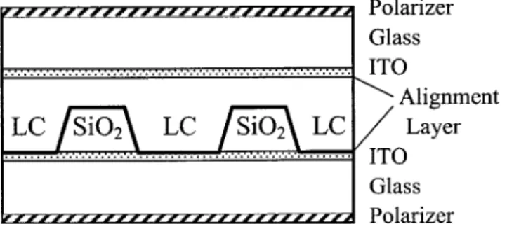
Figure 1. Schematic of the conic CCLCD. In the vector representation, the discretized free energy
expression gives diŒerent free energies for n and Õ n. In
2.1.1. Fabrication of the cavities-glass plate
real nematics, however, n and Õ n are equivalent and
An indium tin oxide (ITO)-coated glass plate was should give the same torque and the same free energy.
used as substrate. It is necessary to clean the substrates When the angle between two neighbouring discretized
to avoid lines and defects on the surfaces. A layer of directors is greater than 90ß , the torque is exerted
silicon dioxide (SiO2) was grown about 3 mm thick on between the two arrows, if the vector representation is
the substrate by plasma enhanced chemical vapour used, rather than between the arrow and the tail, which
deposition. A mask having circles with both diameter make an angle less than 90ß . The Landau–de GennesQ
and interval distances about 90 mm was made for the tensor representation [12, 13] of the elastic free energy
photolithography processes. The exposed substrate was solves this problem. TheQ tensor representation always
coated with positive photoresist and then the pattern incorporates the multiplication of two ns. By using the
transformation was made from mask to SiO2layer. The
Q tensor representation, the disclination position and
exposed regions of positive photoresist layer were dis-form may be changed, and director con gurations can
solved in a developing solution, and the circular hole be more precisely calculated.
pattern was left on the photoresist layer. The BuŒered In this paper, we extend our preliminary investigation
Oxide Etching (BOE) solution is suitable for etching the of the conic CCLCD and give some more detailed results
SiO2layer, but not for etching the ITO layer. After BOE and discussion. We will review the detailed fabrication
pro-had etched out the conic-cylindrical holes completely in cesses and the experimental methods for conic CCLCDs
the SiO2 layer, the photoresist was removed from the in § 2. In § 3 the master equations for calculation are
top of the SiO2 layer. Because we used wet etching derived. Once the director eld is obtained, the
electro-processes that have an almost isotropic etching rate in optical properties can be calculated by the extended
the SiO2 layer, the pro les of the etched holes resemble Jones matrix method [14]. In § 4 we give results about
conical bowls. the stable structure in conic CCLCDs and the optical
characteristics of CCLCDs, comparing also the results
2.1.2. Coating with surfactant
from simulation and from measurement. Also, the
The conic CCLCD has two glass plates: one is the dependence of transmittanc e and contrast ratio on the
cavities-glass plate and the other is an even-glass plate optical parameters has been studied, and we demonstrate
coated with ITO. Before coating surfacant on the surface, improved iso-contrast contours of the conic CCLCD
cleaning processes for the plates are needed to ensure with a c-plate compensator. The transmission versus
the quality of the alignment of the LC in the closed voltage characteristics at normal incidence and oŒ-axis
cavities. A perpendicular alignment of the LC director colour shift of 4-D VAN, 4-D twisted VAN and CCLCDs
on the cavity walls was achieved by coating DMOAP are also compared. Finally, we give our conclusions
(N,N-dimethyl-N-octadecyl-3-am inopropyltrimetho xysilyl
in § 5.
chloride) on both the even-glass plate and the cavities-glass plate. Kahn [15] has shown that anchoring is very
2. Experimental strong between LCs and SiO2 or ITO. 2.1. Sample preparation
The conic CCLCD was fabricated by lling the LC 2.1.3. Filling the L C in the holes
into conic cylindrical cavities as shown in gure 1 (a). Because the LC is viscous in the nematic phase, but These cavities are prepared by the techniques of semi- less viscous in the isotropic phase, we heated the LC to conductor manufacture, so that their geometry and the isotropic phase for lling the cavities. The LC used position can be very well controlled. The fabrication was ZLI-2806 (LC mixture from Merck); the dielectric
constant De is Õ 4.8. process for the conic CCLCD includes the following.
699
Conic cylindrical cavities L CDs
2.1.4. Completing the cell of the LC directors are that n is vertically aligned on
To form closed cavities, the DMOAP-coated smooth the cylinder walls. The electrodes are located on the plate was used to cover the top of the cavity plate. Then upper plane z5 D and the lower plane z 5 0, in which the temperature was lowered to form the nematic phase the voltage V0 is applied. The boundary conditions of and align it in the holes. Next, we used glue to seal the the electric potential areV (z5 0) 5 0, V (z 5 D) 5 V0, and cell and connected conducting wires onto the ITO of V (z 3)5 0.
the two substrates. No additional spacers were provided The stable director eld is the result of the distri-between the SiO2 substrate and the planar substrate. bution of n1,n2,n3, andV that make the free energy Fg
Experimentally, the space between the SiO2substrate and minimal. The master equations to minimize the tensor the planar substrate derives from the assembly process. formulation of the free energy are in the appendix: Eventually it will be controlled using better assembly equations (A7)–(A10).
technology. Other cavity geometry and special design We use the extended Jones matrix (EJM) method, which features can be incorporated for larger aperture ratios. covers large incident angles and arbitrary orientations. It should be noted that, from an electromagnetic wave 2.2. Microscopic observations and measurements point of view, the EJM method is only allowed for the
We used a Leitz polarizing microscope and crossed calculation of light propagation in strati ed, anisotropic, polarizers to observe the optical patterns from the top inhomogeneous media. The distribution of the optical view of the display [7]. There is a very dark eld of axes of the conic CCLCD is inhomogeneous, but it is view with no applied voltage. When the applied voltage not strati ed. Therefore, we modi ed the EJM method is a little greater than the threshold voltage, the pattern to deal with the light propagation in the CCLCD. The of each cavity begins to develop with a circular dark detailed calculation is expressed in the appendix (optical region in the centre and four petal-shaped bright regions simulation).
around the circumference. If the applied voltage is increased continuously, the circular dark region shrinks
and the four bright regions become brighter and expand 4. Results and discussions inwards to the centre. The circular dark region nally
4.1. Stable structure
shrinks to a central point and four dark brushes gradually
To simplify the analysis, the aspect ratio of the conic become apparent. The directions of the dark brushes are
cylinder is 9, the thickness D5 5 mm and the radii RL always coincident with the directions of the polarizers.
andRUare 50 and 45 mm, respectively. The material para-The electro-optical properties were measured by the
meters used in solving the director eld areK5 13.5 pN LCD evaluation system LCD5100 made by Otsuka.
and De5 Õ 4.8. We use the nite diŒerence method (FDM) to solve the master equations (A7)–(A10) in the
3. Theory
appendix, together with the boundary conditions. At Consider a conic CCLCD with a given array of conic
the moment an analytical solution does not exist; only cylinders of LC as shown in gure 2. The thickness of
numerical solutions are available. The start of the numerical the conic cylinders is D, and the radii of upper and
analysis is to discretize the problem. Because the master lower circles are RU and RL, respectively. In the conic
equations are expressed in Cartesian coordinates, we CCLCD, the LC molecules are perpendicularly anchored
generate the grids by cubic meshes. In each grid there on the walls by the surfactant. The boundary conditions
are n1, n2, n3, and V to satisfy the master equations. The algorithm we adopt to solve the equations is the relaxation method. Next we give initial conditions for the director eld and electric potential to start the calculation. We give three kinds of initial conditions that are hyperbolic, radial, and umbilic structures. These initial states all match the boundary conditions of the conic CCLCD. We nd that the initial structure is still preserved under the threshold voltage, but if the applied voltage is larger than the threshold voltage, the most central region of stable structure is always the umbilic structure no matter what the initial condition was. The Figure 2. A local right-handed coordinate systemx, y, and z schematic of the director should be umbilic as shown in
of a conic CCLCD. The thickness of the conic cylinders
gure 3, and it is obvious that there is a central symmetric isD, and the radii of the upper and lower circles are RU
andRL, respectively. structure and no disclination or singularity present.
Figure 3. Schematic of the normal umbilical structure: (a) side view, (b) top view.
4.2. Electro-optical properties
In optical simulation, we choose the wavelength of the incident light to be 550 nm. The birefringence of the liquid crystal is Dn5 0.0437 and the refractive indices ne andnoare 1.5183 and 1.4746, respectively. As mentioned above, we set perpendicular alignment of the directors as the boundary conditions and an umbilic con guration as the initial condition. Then we calculate the stable state of the director eld under the circumstance that no voltage is applied. The stable director eld at zero- eld is the initial condition of the director zero- eld when we calculate the stable director eld induced by an applied voltage. As soon as the director elds are obtained, the transmittance at an applied voltage can be calculated by the optical simulation method. The dependence of transmittance on applied voltage and viewing angle will be studied, and iso-contrast contours will also be obtained. Finally, the transmittance of the conic CCLCD will be optimized by optical parameters.
4.2.1. Azimuthal angle w5 0ß
The director of the conic CCLCD is a centrally symmetric structure. This symmetry will never appear as the optical pattern of a conic CCLCD, when the conic CCLC is between crossed polarizers. We de ne
(a)
(b)
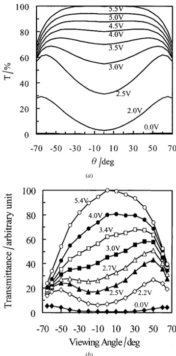
that the direction of the azimuthal angle w5 0ß of the Figure 4. (a) Simulation results and (b) experimental results for the viewing angle-dependent normalized transmittance conic CCLCD is the transmission axis of the polarizer.
(T ) at azimuthal angle w5 0ß . The simulation result for the threshold voltage is 1.9 V,
which is coincident with the experimental result. Figure 4 shows the simulation and experimental results for the
h± T (viewing angle–transmittance) curves at diŒerent conditions is cylindrical. Therefore, in the simulation results, the transmittance curves are symmetric with voltagesV , but xed w5 0ß . The transmittance increases
as the applied voltage increases; hence there is no grey- respect to w5 0ß . However in the experimental results, we cannot nd symmetry in the grey levels. The asym-scale inversion in this azimuthal angle. Ideal polarizers are
assumed in the simulation; hence the dark state in the metry of transmittance is caused by the asymmetric alignment of the director eld in the conic CCLC. We simulation is much better than that found experimentally .
It is a reasonable assumption that the director eld is believe the preparation processes disturb the symmetry of the boundary conditions.
cylindrically symmetric if the symmetry of the boundary
701
Conic cylindrical cavities L CDs
4.2.2. Azimuthal angle w5 45ß viewing angle. This is due to light leakage [16] and will When xed at w5 45ß , gure 5 shows the simu- occur with crossed polarizers at w5 45ß . This will be lation and experimental results of h± T (viewing angle– improved by adding a c-plate compensation lm. It is transmittance) curves at diŒerent voltagesV . The trans- obvious that the simulation and experimental results mittance increases as the applied voltage increases. are similar.
The maximal transmittance at diŒerent viewing angles decreases as the viewing angle increases at higher applied
4.2.3. Iso-contrast
voltages. When V<Vth, transmittance increases as the
The contrast is the ratio (CR) of transmittance between
the bright state and the dark state. In conic CCLCDs, the dark state is at a voltage smaller than the threshold and the bright state is at a higher voltage. Figure 6 shows the iso-contrast contours obtained from simu-lations and experiments in which the applied voltages are 0 V for the dark state and 5.0 V for the bright state. The iso-contrast contours can demonstrate the angular viewing capabilities. In general, the contour withCR5 10 limits the viewing angle of the display. Furthermore the maximal contrast has an eŒect on the image quality. The dark state of a conic CCLCD is almost like a homeotropic aligned LCD except for those directors near the side wall. It is well known of course that the homeotropic aligned LC has a very perfect dark state between crossed polarizers. The contour with CR5 10 extends to 70ß on the left, right, upper, and lower sides. It is obvious that the symmetry of the simulation results is diŒerent from that of the experimental results. The reasons are the same as those mentioned above and based upon the non-uniformity of the cell gap. If the treatment of the boundary conditions is improved experi-mentally, the contours will be symmetric. There is degradation of the contrast ratio in terms of the azi-muthal angle (w5 45ß , 135ß , 255ß , 315ß ), which is veri ed as being due to restrictions in the characteristics of the crossed polarizers.
4.2.4. Dependence of transmittance and contrast ratio on optical parameters
In order to obtain more detailed optical properties of conic CCLCDs, we simulated the dependence of trans-mittance (T ) and contrast ratio (CR) on the optical
parameter (Dnd/l) of the LC, where Dn5 neÕ no andne is the maximum refractive index of the extraordinary ray. We nd that the dependences of T on Dnd/l are similar at w5 45ß and w 5 0ß , when V 5 5 V. Figure 7 (a) shows the dependence of transmittance on optical para-meter Dnd/l at w5 45ß . Apparently, both the regions 0.6< Dnd/l < 0.66 and 1.6 < Dnd/l < 1.93 are good choices. The latter has higher light transmittance than the former in the bright state, while the former is better (a)
(b)
in the dark state and in contrast ratio. When w5 0ß and Figure 5. (a) Simulation results and (b) experimental results
Dnd/l< 1.6, the viewing angle (CR>10) is larger than for the viewing angle-dependent normalized transmittance
(T ) at azimuthal angle w5 45ß . 70ß . This results from the good dark state where the LC
(a)
(b)
Figure 7. The viewing angle dependence of (a) Dnd/l-transmittance and (b) Dnd/l-contrast ratio at azimuthal (a)
(b)
angle w5 45ß . Figure 6. (a) Simulation results and (b) experimental results
for iso-contrast ratio contours, where 0 V was used for the dark state and 5.0 V for the bright state.
4.2.5. Adding a compensator
It is well known that adding a compensator to the molecules are perpendicular to the boundary and the
azimuthal angle w5 0ß is parallel to the polarizer between LCD will increase the viewing angle. For example, if we want to improve the overall viewing angle, we choose crossed polarizers. Figure 7 (b) shows the dependence of
CR on Dnd/l at w5 45ß . It is obvious that the viewing the Dnd/l of the LC to be 0.6, and then add a c-plate
compensator of which the optical parameter Dnd/l is
angle is not good because there is light leakage in the
dark state when w5 45ß with crossed polarizers. negative (we put it about Õ 0.36) between the polarizer
703
Conic cylindrical cavities L CDs
and conic CCLC. The nal iso-contrast contour is shown in gure 8. It is obvious that the viewing angle is improved.
4.3. Comparison with four-domain VAN and four-domain twisted VAN devices
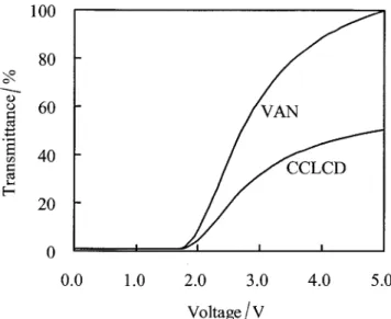
4.3.1. Voltage–transmittance curve
A simple one-dimensional director eld calculation for these devices and summation of the optical behaviour of CCLC and 4-D VAN devices are obtained by using Wang’s LCD simulator of the National Chiao Tung University (NCTU), Taiwan. The voltage–transmittance curve is shown in gure 9. The threshold voltage of the CCLCD is the same as that of the 4-D VAN. The bright state of the CCLCD is one half of that of 4-D VAN in theory. This is because the director con guration is
Figure 9. Voltage–transmittance curve for the CCLCD and circularly symmetric, while the polarizers are crossed. If
the 4-D VAN device at normal incidence. the incident light is circularly polarized, the bright state
of the CCLCD will be increased. Besides it is an ideal condition that the 4-D VAN is aligned such that the optic axis of each domain is switched to be at 45ß to
the chromaticity diagram. In order to study the oŒ-axis the crossed polarizers. We predict that the bright state
colour shift (i.e. colour coordinate change as a function of the CCLCD is in fact larger than one half of that of
of h) of the CCLCD, we employed the backlight for a the 4-D VAN.
typical LCD monitor (CCFL, cold cathode uorescent lamp). Because the wavelength of the maximum bright-ness of a CCFL is 545 nm, Dnd can be calculated as
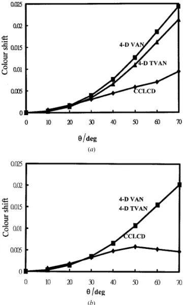
4.3.2. OV-axis colour shift
348.8 nm for maximum transmittanc e at normal incidence We de ne the oŒ-axis colour shift as the distance from
from gure 7 (a). To keep Dnd constant at 348.8 nm, the
the viewing angle h to h5 0 for normal incidence in
dependence of transmittanc e on wavelength for diŒerent viewing angles h can be obtained in gure 7 (a). Therefore, the coordinate of the chromaticity diagram (x, y) and
the oŒ-axis colour shifts were also calculated at diŒerent viewing angles. The results for the colour shifts for w5 45ß and w 5 0ß are shown in gures 10 (a) and 10 (b), respectively.
Next, the coordinates of the chromaticity diagram (x, y) were calculated at diŒerent viewing angles for the
4-D VAN, and 4-D twisted VAN using LCD Master of the Shintek Corp. The backlight, polarizers and para-meters of the LC in the 4-D VAN and 4-D TVAN devices are the same as those for the CCLCD. The oŒ-axis colour shifts of 4-D VAN and 4-D TVAN were also calculated at diŒerent viewing angles. The result for the colour shift are shown in gure 10. It is obvious that the oŒ-axis colour shift for the CCLC is much less than that for the 4-D VAN and 4-D TVAN at higher viewing angles (h larger than 30ß ). When h is less than 30ß , there are similar colour shifts in the three LCD modes. It is also shown that the 4-D VAN has a larger oŒ-axis colour shift than the 4-D TVAN for w5 45ß in gure 10 (a). Figure 8. Simulation results of iso-contrast ratio contours for
However, the 4-D VAN shows the same oŒ-axis colour the conic CCLCD with ac-plate compensator, where 0 V
was used for the dark state and 5.0 V for the bright state. shift as the 4-D TVAN for w5 0ß in gure 10 (b).
CCLCD, and it was obvious that the viewing angle was improved. The oŒ-axis colour shift has also been studied, and that for the CCLCD is less than those for 4-D VAN and 4-D twisted VAN devices.
This research was supported in part by the Chinese National Science Council under Contract No. NSC 89-2112-M-035-00 7 and the Electronics Research & Service Organization of the Industrial Technology Research Institute, Taiwan, ROC. The authors also acknowledge the Nano Device Laboratory, Taiwan, ROC. We are indebted to Prof. J. J. Wu of the Department of Physics, Soochow University, Taipei, and Dr C.-K. Wei of the Chi Mei Optoelectronic Corporation, Tainan, Taiwan, ROC, for useful discussions.
Appendix
Consider a conic CCLCD with a given array of conic cylinders of the LC as shown in gure 2. The thickness of the conic cylinder cylinders is D and the radii of
upper and lower circles are RUand RL, respectively. In the conic CCLCD, the LC molecules are perpendicularly anchored on the walls by the surfactant. The boundary conditions of the LC directors are that n is vertically aligned on the cylinder walls. The electrodes are located on the upper plane z5 D and the lower plane z 5 0, in which the voltageV0is applied. The boundary conditions of the electric potential are V (z5 0) 5 0, V (z 5 D) 5 V0, andV (z 3)5 0.
Director modelling
The tensor formulation of the deformation energy (a)
(b)
Figure 10. OŒ-axis colour shift (i.e. colour coordinate change density, Fs, expressed by Cartesian coordinates is as a function of h) for the CCLC, 4-D VAN device, and
4-D twisted VAN device for (a) w5 45ß and (b) w 5 0ß .
Fs5 K4Qjk,lQjk,l, i, j, k, l 5 1, 2, 3 (A1)
5. Conclusion
In conclusion, conic CCLCD with wide viewing angle
Qij 5 12Q(3ninjÕ dij) (A2)
have been demonstrated by simulation and by experi-ment. The simulation of director distribution was based
on the tensor form formulation of the free energy density. Qij,l 5 qQij
qx1 , x15 x, x25 y, x35 z (A3) The simulation of the optical propagation and the
calculation of the optical transmittance were based on
where K is the approximated Frank elastic constant,
the extended Jones matrix method. We have described
and Qij is the element of the order parameter tensor of the fabrication process, microscopic observations and
the LC. In tensor calculus, it is quite advantageou s to optical measurements for conic CCLCD in detail. The
make use of the Einstein summation convention, i.e. viewing angle is about Ô 70ß for contrast ratios larger
AiBi 5 A1B11 A2B21 A3B3. The symbol dij is the than ten in both the horizontal and vertical directions,
Kronecker delta, which is de ned as and absence of grey-scale inversion has been
demon-strated. Also, we have studied the dependence of trans-mittance and contrast ratio on optical parameters.
dij 5
G
0, if i1, if i5 jÞ j. Finally, we added a c-plate compensator to a conic705
Conic cylindrical cavities L CDs
The coupling between the electric eld and director column lie parallel to the substrate. Each element is assumed to have uniaixal birefringence, with a uniform eld gives rise to a free energy density
optic axial direction. The optic axes of each element can be interpolated by results from the front sections and
Fe5 12e0ejkV,jV,k1 1
2e0DeV,jV,kQjk, i, j, k 5 1, 2, 3
vary from element to element. Because the molecular director of the LC is continuous, the change in refractive (A4)
index is small; we assume that the light will not refract outside the primary column. The passage of light through
V,j 5 qqxjV (A5) each column of cells is considered in turn; the
trans-mittance of each column is calculated by the EJM where ejk corresponds to the element of the relative method and the total transmittance of the CCLCD is permittivity tensor, De denotes the dielectric anisotropy,
the summation of all the columns. and V is the electric potential. The free energy density
Consider a column withN sublayers; in each sublayer,
of the LC is
the medium is assumed to be uniaxial and homogeneous,
Fg5 FsÕ Fe. (A6) but the orientations of the optic axis are diŒerent. For a given incident electric eld (As,Ap), the transmitted The stable director eld is the result of the distribution
electric eld (A¾s,A¾p) can be calculated by ofn1,n2,n3, andV that make the free energy Fgminimal.
The master equations to minimize the free energy can
C
AsAp
D
5 MAMLCMPC
As Ap
D
be obtained by using the variation method as follows.
MLC5 DAgPNDNÕ 1,NPNÕ 1DNÕ 2,NÕ 1¼ qFg qn1Õ d dx1
A
qFg qn1,x 1B
Õ d dx2A
qFg qn1,x 2B
D 2,3P2D1,2P1DPg, Õ d dx3A
qFg qn1,x 3B
5 0 (A7)Dj,j+1 5
C
oÃj ¯oÃj+1 eÃj ¯oÃj+1oÃj ¯eÃj+1 eÃj ¯eÃj+1D
qFg qn2Õ d dx1
A
qFg qn2,x 1B
Õ d dx2A
qFg qn2,x 2B
whereDj,j+1 is the dynamic matrix between the jth and (j1 1)th sublayers, and Pj is the transfer matrix of the jth sublayer. The unit vectors of the eigen-modes, oà and
Õ d dx3
A
qFg qn2,x 3B
5 0 (A8)eÃ, in each sublayer are given by oÃ5 cÃ3 ko
|
cÃ3 ko|
; eÃ5 ko3 oÃ|
ko3 oÃ|
. qFg qn3Õ d dx1A
qFg qn3,x 1B
Õ d dx2A
qFg qn3,x 2B
TheMAandMPare matrices of analyser and polarizer,
Õ d
dx3
A
qFg
qn3,x
3
B
5 0 (A9) respectively. They can be expressed as
div[e0ejk(= V )k]j 5 0. (A10) M
A5
C
aÃt¯sà aÃa¯sà aÃt¯pà aÃa¯pÃDC
1 0 0 0DC
sà ¯ aÃt pà ¯ aÃt sà ¯ aÃa pà ¯ aÃaD
Optical simulationWe use the extended Jones matrix (EJM) method, which M P5
C
pÃt¯sà pÃa¯sà pÃt¯pà pÃa¯pÃDC
1 0 0 0DC
sà ¯ pÃt pà ¯ pÃt sà ¯ pÃa pà ¯ pÃaD
covers large incident angles and arbitrary orientations. This method is simpler than the 43 4-matrix method
where pÃt, pÃa, aÃt, aÃa are unit vectors of the transmission and thus requires less computation time. It should be
axis of the polarizer, the absorption axis of the polarizer, noted here that, from an electromagnetic wave point of
the transmission axis of the analyser, and the absorption view, the EJM method is only allowed for the calculation
axis of the analyser, respectively. Analogously to the of light propagation in strati ed, anisotropic,
inhomo-unit vectors of eigen-modes, these inhomo-unit vectors are given geneous media. However, because the distribution of the
by optical axes of the conic CCLCD is inhomogeneous, but
not strati ed, we modi ed the EJM method to deal with
pÃt5 cÃ3 ki
|
cÃ3 ki|
; pÃa5ki3 pÃt
|
ki3 pÃt|
the light propagatio n in a CCLCD. The optical behaviour of a CCLCD is modelled by dividing the material into
an array of CCLC [17 ]. The column is parallel to the aà t5
cÃ3 ki
|
cÃ3 ki|
; aÃa5ki3 aÃt
|
ki3 aÃt|
incident ray passing into the LC and the sublayers in
[7] Liang, B.-J., Chen, S.-H., and Wang, Y. F., 1998,Appl. where cà and ki are the optic axes of the polarizer
Phys. L ett., 72, 1290. (or analyzer) and the wave vector of the incident light,
[8] Liang, B.-J., Chen, S.-H., Wu, C.-R., Wei, C.-K., and respectively. Also pà and sà are the unit vectors of the Kuo, C.-L., 1998, in Proceedings of SPIE Conference
p-polarization and s-polarization of the incident light, on Display Technologies, Vol. II, pp. 215–222.
[9] Liang, B.-J., Chen, S.-H., Wu, C.-R., Wei, C.-K., and respectively.
Kuo, C.-L., 1999, U.S. Patent 5 978 062.
[10] Wei, J.-G., and Chen, S.-H., 1994, Jpn. J. appl. Phys. 2,
References 33, L660.
[1] Yang, Y. H., 1991,Proc. IDRC’91, 68. [11] Wei, J.-G., and Chen, S.-H., 1994, Jpn. J. appl. Phys. 1, [2] Ohmuro, K., Kataoka, S., Sasaki, T., and Koike, Y., 33, 6249.
1997,SID’97 Dig., 845. [12] Schiele, K., and Trimper, S., 1983, Phys. Stat. Sol., [3] Yamada, N., Kohzaki, S., Funada, F., and Awane, K., 118, 267.
1995,SID’95 Dig., 575. [13] Mori, H., Gartland, E. C., Kelly, J. R., and Bos, P. J., [4] Kuo, C.-L., Miyashita, T., Suzuki, M., and Uchida, T., 1999,Jpn. J. appl. Phys. 1, 38, 135.
1996,Appl. Phys. L ett., 68, 1461. [14] Gu, C., and Yeh, P., 1993,J. opt. Soc. Am., A10, 996. [5] Vithana, H., Fung, Y. K., Jamal, S. H., Herke, R., [15] Kahn, F. J., 1973, Appl. Phys. L ett., 22, 386.
Bos, P. S., and Johnson, D. L., 1995, SID’95 Dig., 873. [16] Herke, R., Jamal, S. H., and Kelly, J. R., 1995,J. SID, [6] Bos, P. J., Vithana, H. K., Johnson, D. L., and Chen, J., 3, 9.
[17] Nichlson, T. M., 1989,Mol. Cryst. liq. Cryst., 177, 163. 2000, U.S. Patent 6 141 074.