330 IEEE MICROWAVE AND WIRELESS COMPONENTS LETTERS, VOL. 24, NO. 5, MAY 2014
Dual-Band Ring Coupler Based on the
Composite Right/Left-Handed Folded
Substrate-Integrated Waveguide
Pei-Ling Chi, Member, IEEE, and Tse-Yu Chen
Abstract—In this letter, a dual-band ring coupler based on
the folded substrate-integrated waveguide (FSIW) is proposed. The artificial structure, the composite right/left-handed (CRLH) transmission lines were implemented in the FSIW by loading the interdigital capacitors in the middle metallic layer to generate a left-handed passband region below the cutoff frequency of the ordinary waveguide mode for coupler miniaturization. The FSIW is the folded counterpart of the substrate-integrated wave-guide (SIW) and thus can prevent the CRLH transmission lines from radiation loss by shielding the interdigital capacitors in the waveguide. Besides, the FSIW-based coupler is able to eliminate the electromagnetic interference (noise) with adjacent objects and lend itself to multilayer circuit integration. A ring coupler that operates at 4.3 and 7.6 GHz was developed and experimentally verified. To the best of the authors’ knowledge, it is the first time that a dual-band rat-race was implemented and reported based on the CRLH-FSIW structure.
Index Terms—Composite right/left-handed (CRLH), dual-band,
folded substrate-integrated waveguide (FSIW), ring coupler.
I. INTRODUCTION
R
ING hybrids that are capable of dual-band or multi-band operation and lend themselves easily to system integra-tion are of great importance for many microwave circuits, such as push-pull amplifiers and balanced mixers, in ever demanding communication systems. Dual-band ring hybrids have been ex-tensively reported in the literature [1]–[6]. The microstrip lines in a variety of prototypes, such as the model [1], model [2], and the artificial lines [3], [4], render a facile solution to size-reduced and dual-band couplers, but performance degrada-tion due to the nature of open structures makes microstrip lines less preferable especially for stringent system specifications. The study on the substrate-integrated waveguides (SIWs) [7], [8] to replace the bulky metallic waveguides proposes a useful approach to low loss and inexpensive implementation. The ridge SIW based ring hybrid [5] demonstrates dual-band character-istics by using two concentric ring couplers for the respectiveManuscript received October 07, 2013; revised December 16, 2013; accepted February 12, 2014. Date of publication March 12, 2014; date of current version May 06, 2014. This work was supported in part by the National Science Council of Taiwan under Grant NSC 101-2221-E-009-108 and Grant NSC 102-2221-E-009-029.
The authors are with the Department of Electrical and Computer Engineering, National Chiao Tung University, Hsinchu, Taiwan (e-mail: peilingchi@ nctu. edu.tw).
Color versions of one or more of the figures in this letter are available online at http://ieeexplore.ieee.org.
Digital Object Identifier 10.1109/LMWC.2014.2309087
bands. The implementation of ridges as well as the radial trans-verse slots over the un-ridged wall of the outer coupler needs precise drilling and machining, leading to considerable fabrica-tion cost. The dual-band coupler [6] by dispersion engineering of the composite right/left-handed (CRLH) transmission lines was developed with the half-mode SIW where the interdigital capacitors on top metal surface become the unwanted radiation source and degrade the overall performance.
Recent investigation on the folded substrate-integrated wave-guide (FSIW) [9] shows that the FSIW can reduce the width by about one half while exhibiting nearly identical dispersion char-acteristics when compared to the SIW, indicating the possibility for size reduction. Moreover, when applying the CRLH trans-mission line theory, the interdigital capacitors can be designed in the middle metallic layer enclosed completely by the top and bottom ground planes, maintaining the radiation-free property of a closed structure [10]. The FSIW structures have been used for applications of filters and coupled-line couplers [10]–[12], but less effort was made on the dual-band ring couplers. There-fore, in this work, the FSIW technology was applied for realiza-tion of a dual-band coupler where the model of the CRLH trans-mission line was developed by inserting the interdigital capac-itors to generate a left-handed passband mode below the cutoff frequency of the waveguide mode, allowing for passband operation at lower frequencies [10]. The proposed coupler is compatible with planar PCB circuitry or can be easily integrated into multilayer circuitry. Details on structural parameters and design procedure will be given in next sections. Good agreement is achieved between measured and full-wave simulated results.
II. COUPLERDEVELOPMENT ANDDESIGNPROCEDURE
The proposed dual-band CRLH rat-race coupler was devel-oped in the FSIW, consisting of two stacked layers of the Rogers 5880 substrates of thickness and of dielectric con-stant . In order to mitigate the effects from the dielec-tric loss and dielecdielec-tric constant of the bonding film, the Rogers 3001 bonding film ( , ) was used, which was shown effective for loss reduction [10]. This cou-pler has three metallic layers with ground planes on the top and bottom layers, and the interdigital capacitors were introduced in the middle layer to develop the model of the CRLH transmis-sion lines as shown in Fig. 1. The correspondence between the physical structure and the lumped elements of the CRLH lines will be detailed in Section II-A. The proposed coupler is fed by the conductor-backed coplanar waveguide (CB-CPW) in order to comply with the mode distribution in the FSIW where
1531-1309 © 2014 IEEE. Personal use is permitted, but republication/redistribution requires IEEE permission. See http://www.ieee.org/publications_standards/publications/rights/index.html for more information.
CHI AND CHEN: DUAL-BAND RING COUPLER BASED ON THE CRLH FSIW 331
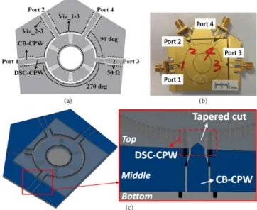
Fig. 1. (a) Configuration of the middle metallic (signal) layer, (b) the photo-graph and (c) the perspective view of the proposed dual-band ring hybrid based on the FSIW structure. The close-up of the feeding structure and the tapered transition section is shown for clarity.
the electric field is most concentrated around the gap along the outer perimeter of the ring and is oriented in the horizontal direc-tion. Note that the upper substrate is smaller than the lower sub-strate simply for convenience of the feed line design. In addition to the via arrays (denoted as via_1-3) used as the side walls, the vias on both sides (denoted as via_2-3) of the signal strip of the CB-CPW are used to connect the lateral ground planes (middle layer) to the bottom ground plane, avoiding the excitation of the parallel-plate mode.
A. The 90 Sections
As shown in Fig. 1(a), the dual-band ring hybrid is composed of six identical CRLH unit cells, each of which was designed to exhibit a 90 phase advance and a 90 phase delay at the first and the second bands, respectively. The details of the pro-posed unit cell are given in Fig. 2. The two arrays of vias along the perimeter of the ring arm form side walls of the FSIW and connect the middle metallization to the top and bottom ground planes (via_1-3). The vias are 0.55 mm in diameter, and via dis-tances are 0.78 mm and 0.8 mm for inner and outer arrays, re-spectively. Referring to Fig. 2(b) for the CRLH circuit model, the interdigital capacitors in the unit cell contribute to the series capacitance while the shunt inductance is determined by the inner vias and the width of the conductor strip. In addition, the series inductance and shunt capacitance are resulted from the distributed inductance and capacitance of the waveguide, respectively. The unit cell is optimized in a fashion that the desired phase and impedance responses are ful-filled in both bands. The physical dimensions are as follows:
, , , ,
gap and width of the interdigital capacitors are both 0.17 mm. Based on these parameters, Fig. 3 shows the full-wave char-acterization of the dispersion relation and impedance. The unit cell shows the 90 phase-leading at 4.3 GHz in the left-handed region while having the 90 phase-lagging at 7.6 GHz in the right-handed region. Furthermore, the impedances of 70.7 are
Fig. 2. (a) Top view of the middle layer and (b) the lumped-element correspon-dence of the proposed unit cell with the CRLH equivalent circuit parameters.
Fig. 3. Full-wave (HFSS) calculated phase (solid) and impedance (dashed) re-sponses of the proposed CRLH unit cell. The dispersion relation (with circle symbol) calculated from the circuit model is illustrated and the lumped
param-eters are , , ,
.
obtained in both bands. The extracted lumped parameters of the proposed unit cell are given in Fig. 3 where the corresponding dispersion curve of the circuit model is compared. Note that the CRLH circuit model shown in Fig. 2(b) is a simplified model and it is valid only in a limited frequency range. In addition, in Fig. 3 the high-pass cutoff frequency of the left-handed region occurs at about 4 GHz, which is considerably lower than the cutoff of the original (unloaded) FSIW at about 6.6 GHz and thus offers the advantage for size reduction. Moreover, due to the close proximity to the cutoff, the variations of the dispersion and impedance curves versus frequency are large at , resulting in the narrow bandwidth in the first band. The left-handed pass-band can be reduced further by increasing interdigital capaci-tance and thus results in an enhancement of dual-band frequency ratio, but the self-resonance of the capacitors will occur and de-grade the performance in the second band. For demonstration purpose only, the frequency ratio of 1.8 is implemented in this work.
B. The Tapered Transition Sections
In order to feed the FSIW coupler by the CB-CPW, a tran-sition section, which is termed as the double-sided conductor CPW (DSC-CPW), was designed and illustrated in Fig. 1(c). Note that the DSC-CPW is a three-metal-layer architecture where the CPW-like geometry is designed in the middle plane to connect the input CB-CPW while the top/bottom surfaces are ground planes and consistent with those of the FSIW. Thus the DSC-CPW can mainly maintain field distribution of the CB-CPW for proper excitation. Furthermore, in addition to the tapered signal line, a tapered cut in the top metallization
332 IEEE MICROWAVE AND WIRELESS COMPONENTS LETTERS, VOL. 24, NO. 5, MAY 2014
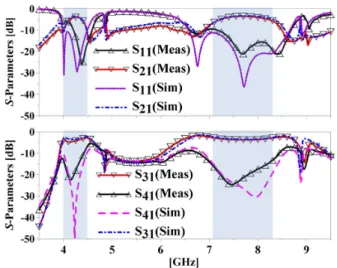
Fig. 4. Measured and simulated -parameters obtained at port 2 ( port).
Fig. 5. Measured and simulated -parameters obtained at port 1 ( port). TABLE I
COMPARISON OFCOUPLERPERFORMANCES
Size reduction is determined by comparing the ring footprint of the dual-band coupler to the single-band, microstrip hybrid operating in the lower band of the dual frequencies when the same substrate is employed.
was used to reduce the reflection at waveguide discontinuity as shown in Fig. 1(c).
III. SIMULATED ANDMEASUREDRESULTS
The proposed ring coupler was experimentally developed on two stacked laminates (Rogers 5880) with three metal layers to implement the FSIW. Fig. 1(b) shows the photograph of the fabricated coupler with the ports numbering convention as in-dicated. The measured -parameters are given in Figs. 4 and 5 and compared to the HFSS-simulated results. Very good agree-ment was obtained. Due to the limited space, only the magnitude
responses are given here. The dual-band characteristics are ver-ified both by measurement and simulation. The measured inser-tion losses are 3.7 dB and 3.5 dB at port, and 3.9 dB and 3.5 dB at port at 4.3 and 7.6 GHz, respectively. Measured insertion losses are slightly higher than those from simulation and can be ascribed to the fabrication error. In addition, the measured band-widths for 15 dB return loss are 4.6% and 13.9% at port, and 5.7% and 14.1% at port. The bandwidths for 15 dB isolation are 7.0% and 15.5% at 4.3 and 7.6 GHz, respectively. The mea-sured bandwidths obtained at ports for 1 dB magnitude imbalance are 3.7%/5.7% and 11.2%/10.1% at 4.3 and 7.6 GHz, respectively. Similarly, the bandwidths obtained at ports for 10 phase imbalance are 6.8%/6.7% and 13.6%/13.1%. As expected and discussed in Section II-A, smaller fractional band-widths at the lower passband are observed. In Table I, the com-parison of the coupler performances is given.
IV. CONCLUSION
A dual-band ring coupler was developed and fabricated based on the CRLH-FSIW structure. The proposed prototype is well suited for applications of low loss and multilayer circuitry inte-gration.
REFERENCES
[1] K.-S. Chin, K.-M. Lin, Y.-H. Wei, T.-H. Tseng, and Y.-J. Yang, “Compact dual-band branch-line and rat-race couplers with stepped-impedance-stub lines,” IEEE Trans. Microw. Theory Tech., vol. 58, no. 5, pp. 1213–1221, May 2010.
[2] C.-L. Hsu, J.-T. Kuo, and C.-W. Chang, “Miniaturized dual-band hy-brid couplers with arbitrary power division ratios,” IEEE Trans. Mi-crow. Theory Tech., vol. 57, no. 1, pp. 149–156, Jan. 2009.
[3] P.-L. Chi and T. Itoh, “Miniaturized dual-band directional couplers using composite right/left-handed transmission structures and their ap-plications in beam pattern diversity systems,” IEEE Trans. Microw. Theory Tech., vol. 57, no. 5, pp. 1207–1215, May 2009.
[4] G. Siso, J. Bonache, and F. Martin, “Dual-band rat race hybrid coupler implemented through artificial lines based on complementary split ring resonators,” in IEEE MTT-S Int. Dig., Boston, MA, 2009, pp. 625–628. [5] T. Djerafi, H. Aubert, and K. Wu, “Ridge substrate integrated wave-guide (RSIW) dual-band hybrid ring coupler,” IEEE Microw. Wireless Compon. Lett., vol. 22, no. 2, pp. 70–72, Feb. 2012.
[6] Y. Dong and T. Itoh, “Application of composite right/left-handed half-mode substrate integrated waveguide to the design of a dual-band rat-race coupler,” in IEEE MTT-S Int. Dig., Anaheim, CA, 2010, pp. 712–715.
[7] D. Deslandes and K. Wu, “Integrated microstrip and rectangular wave-guide in planar form,” IEEE Microw. Wireless Compon. Lett., vol. 11, no. 2, pp. 68–70, Feb. 2001.
[8] Y. Cassivi, L. Perregrini, P. Arcioni, M. Bressan, K. Wu, and G. Con-ciauro, “Dispersion characteristics of substrate integrated rectangular waveguide,” IEEE Microw. Wireless Compon. Lett., vol. 12, no. 9, pp. 333–335, Sep. 2002.
[9] W. Che, L. Geng, K. Deng, and Y. Chow, “Analysis and experiments of compact folded subsrate-integrated waveguide,” IEEE Trans. Microw. Theory Tech., vol. 56, no. 1, pp. 88–93, Jan. 2008.
[10] T. Yang, P.-L. Chi, R. Xu, and W. Lin, “Folded substrate integrated waveguide based composite right/left-handed transmission line and its application to partial H-plane filters,” IEEE Trans. Microw. Theory Tech., vol. 61, no. 2, pp. 789–799, Feb. 2013.
[11] N. Grigoropoulos, B. Sanz-Izquierdo, and P. R. Young, “Substrate inte-grated folded waveguides (SIFW) and filters,” IEEE Microw. Wireless Compon. Lett., vol. 15, no. 12, pp. 829–831, Dec. 2005.
[12] G. Zhai, W. Hong, K. Wu, J. Chen, P. Chen, J. Wei, and H. Tang, “Folded half mode substrate integrated waveguide 3 dB coupler,” IEEE Microw. Wireless Compon. Lett., vol. 18, no. 8, pp. 512–514, Aug. 2008.