Dynamics of optical backward-injection-induced
gain-depletion modulation and mode locking
in semiconductor optical amplifier fiber lasers
Gong-Ru Lin and Yu-Sheng Liao
Institute of Electro-Optical Engineering, National Chiao Tung University, Hsinchu, Taiwan 300, China
Guang-Qun Xia
Department of Physics, Southwest Normal University, ChongQing 400715, China
Abstract: The optical gain-depletion-induced mode-locking dynamics of a
semiconductor optical-amplifier–based fiber ring laser (SOAFL) backward injected by a purely sinusoidally modulated or digitally encoded distributed-feedback laser diode are theoretically and experimentally demonstrated. The effect of gain depletion and waveform on the mode-locked pulse width, pulse shape, and power of the SOAFL are interpreted from theoretical simulations. The shortest pulse width of 12 ps can be generated from an optically sinusoidal-wave-modulated SOAFL. By backward injecting the SOAFL with a digitally encoded optical signal of adjustable duty cycle, one can observe the optimized gain depletion time of 400–600 ps required for mode locking the SOAFL.
©2004 Optical Society of America
OCIS codes: (320.5540) Pulse shaping; (140.4050) Mode-locked lasers.
References and links
1. J. D. Kafka, T. M. Baer, and D. W. Hall, “Mode-locked erbium fiber laser,” in Conference on Lasers and
Electro-Optics, Vol. 11 of 1989 OSA Technical Digest Series (Optical Society of America, Washington, D.C.,
1989), paper FA3.
2. E. Yoshida and M. Nakazawa, “80–200 GHz erbium doped fiber laser using a rational harmonic mode-locking technique,” Electron. Lett. 32, 1370-1372 (1996).
3. A. Takada and H. Miyazawa, “30 GHz picosecond pulse generation from actively mode-locked erbium-doped fiber laser,” Electron. Lett. 26, 216-217 (1990).
4. J. S. Wey, J. Goldhar, D. W. Rush, M. W. Chbat, G. M. Carter, and G. L. Burdge, “Performance characterization of a harmonically mode-locked erbium fiber ring laser,” IEEE Photon. Technol. Lett. 7, 152-154 (1995). 5. J. B. Schlager, Y. Yamabayashi, D. L. Franzen, and R. J. Juneau, “Mode-locked long-cavity erbium fiber lasers
with subsequent soliton-like compression,” IEEE Photon. Technol. Lett. 1, 264-266 (2001).
6. U. Koren, B. I. Miller, M. G. Young, T. L. Koch, R. M. Jopson, A. H. Gnavok, J. D. Evankow, and M. Chien, “High frequency modulation of strained layer multiple quantum well optical amplifiers,” Electron. Lett. 27, 62-64 (1991).
7. D. M. Patrick, “Modelocked ring laser using nonlinearity in a semiconductor laser amplifier,” Electron. Lett. 30, 43-44 (1994).
8. T. Papakyriakopoulos, K. Vlachos, A. Hatziefremidis, and H. Avramopoulos, “20-GHz broadly tunable and stable mode-locked semiconductor amplifier fiber ring laser,” Opt. Lett. 24, 1209-1211 (1999).
9. T. Papakyriakopoulos, A. Hatziefremidis, T. Houbavlis, and H. Avramopoulos, “10 GHz mode-locked ring laser with external optical modulation of a semiconductor optical amplifier,” in Optical Fiber Communication
Conference (Institute of Electrical and Electronics Engineers, Piscataway, N. J., 1999), pp. 4-6, paper TuB1.
10. K. Zoiros, K. Vlachos, T. Stathopoulos, C. Bintjas, and H. Avramopoulos, “40 GHz mode-locked SOA fiber ring laser with 20 nm tuning range,” in Optical Fiber Communication Conference (Institute of Electrical and Electronics Engineers, Piscataway, N. J., 2000), pp. 254-256.
11. K. Vlachos, K. Zoiros, T. Houbavlis, and H. Avramopoulos, “10 simultaneously mode-locked and synchronized channels at 30 GHz from fiber ring laser,” in Optical Fiber Communication Conference (Institute of Electrical and Electronics Engineers, Piscataway, N. J., 2000), pp. 344-246.
12. L. Schares, L. Occhi, and G. Guekos, “Picosecond wavelength tunable SOA-based laser sources at 10-40 GHz repetition rates,” in Conference on Lasers and Electro-Optics (CLEO), Vol. 73 of OSA Trends in Optics and Photonics Series (Optical Society of America, Washington, D. C., 2002), pp. 56-57, paper CML3.
13. J. He and K. T. Chan, “All-optical actively modelocked fibre ring laser based on cross-gain modulation in SOA,” Electron. Lett. 38, 1504-1505 (2002).
14. G.-Q. Xia, Z.-M. Wu, and G.-R. Lin, “Rising and falling time of amplified picosecond optical pulse by semiconductor optical amplifiers,” Opt. Commun. 227, 165-170 (2003).
15. A. E. Willner and W. Shieh, “Optimal spectral and power parameters for all-optical wavelength shifting: single stage, fanout, and cascadability,” J. Lightwave Technol. 13, 771-781 (1995).
1. Introduction
Gain and loss modulation are well-known techniques for achieving mode locking in versatile lasers. A loss-modulation technique that uses a bulk or integrated electro-optic modulator has produced actively mode-locked erbium-doped fiber lasers (EDFLs) [1-5] with picosecond pulse widths or ultrahigh (30–160-GHz) repetition rates. However, the EDFL cannot be gain modulated because of its extremely long carrier lifetime (as much as several milliseconds). Alternatively, semiconductor-optical-amplifier- (SOA-) based fiber lasers (referred to hereafter as SOAFLs) can overcome this drawback because they have subnanosecond carrier lifetimes [6]. The direct gain modulation of a SOA by periodic control of the driving current was employed previously as the main means to mode lock SOAFLs: The mode-locked pulse formed behind the externally injected pulse when the recovered gain exceeded the cavity losses. Later, all-optical gain modulation of SOAs by periodic depletion of their gain through forward optical injection was performed. In particular, Patrick [7] demonstrated an actively rational-harmonic mode-locked EDFL with 8.4-ps pulses at a repetition rate of 20 GHz by using an all-optical modulated SOA as a mode locker. In this approach, the SOA was operated in a high-gain condition and was gain depleted by a high-power mode-locked laser diode, resulting in complicated phase and amplitude modulation of the light circulated in the EDFL. Similar experiments were also implemented by gain depletion of the SOA by use of a gain-switched and pulse-compressed distributed-feedback laser diode (DFBLD) [8, 9], generating a mode-locked pulse width of 4.3 ps in such a cross-gain-modulating configuration. The SOA acted as both the gain medium and the modulator in the techniques described above, whereas the mode locking was initiated after fast periodic gain depletion and relatively slow gain recovery in the SOA during strong pulse injection. The injected optical pulse results in a temporally short gain window, which must be adjusted at wavelengths different from those of the mode-locking pulses. The optical injection was subsequently filtered out to prevent the occurrence of regenerative amplification in the SOAFL. More recently, higher-repetition-rate (up to 40 GHz), shorter-pulse-width (1.8-ps), and wider-wavelength tuning ranges (~20 nm) were obtained from SOAFLs by use of an all-optical modulating technique [10-12] . Notably, multiwavelength channeled output has also been reported [13].
Cross-gain modulation can also be achieved by forward or backward injection of the SOA in a low-biased (or near threshold) condition with a periodically (sinusoidal wave or pulse) modulated laser source, which can also induce gain-depletion (or loss) modulation as well as mode locking of the SOAFL at various wavelengths. The injection rate is therefore sufficiently high to saturate the SOA and to deplete its excited-state electrons. In this case the SOA can be employed as a loss modulator for an EDFL or a SOAFL with a separate constant-gain medium. We have studied experiments on cross-gain-modulation-based mode locking of SOAFLs in detail, but we found few analytical or simulated approaches to this phenomenon. In particular, a comparison between sinusoidal-wave- and pulsed-injection-induced cross-gain modulation was not described. By contrast, we report here both a theoretical simulation and an experimental demonstration of a mode-locked SOAFL by use of a backward-optical-injected SOA as a loss modulator. A theoretical model to explain the effect of a modulating waveform on the mode-locking performance of a SOAFL is reported. Various mode-locking results of the SOAFL with sinusoidal-wave and pulse-modulated SOAs, and their correlation with the gain depletion dynamics, are also discussed and compared. The buildup of a harmonic-mode-locked SOA fiber laser is accomplished primarily by backward injection of the SOA with a digital–transistor-transistor-logic- (TTL-) encoded DFBLD. One can determine the shortest gain-depletion time required for buildup of harmonic mode locking of a SOAFL by adjusting the duty cycle of the TTL signal. The #3846 - $15.00 US Received 19 February 2004; revised 8 April 2004; accepted 9 April 2004
optimized pulse widths of the mode-locked SOAFL at various repetition frequencies are also reported.
2. Experimental setup
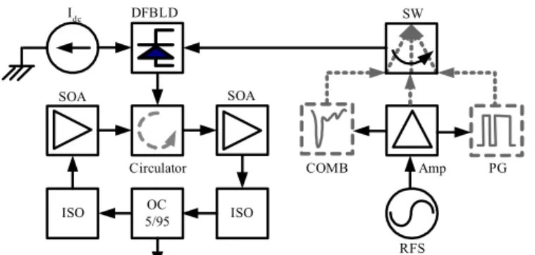
Figure 1 illustrates the backward-optical-injection mode-locked SOAFL system, which consists of two traveling-wave-type SOAs with a saturation gain of 21 dB, a 1.3-µm butterfly-packaged DFBLD with a central wavelength of 1309 nm at a temperature of 15 oC, an optical
circulator, two Faraday isolators, and an optical coupler with a power-splitting ratio of 95:5. The first SOA, which is dc biased slightly above threshold (72 mA) is backward injected by the sinusoidal-wave-modulated or digitally encoded DFBLD, whereas the second SOA, which is dc biased at 142 mA, is employed to offer constant gain without any modulation. In principle, the first SOA functions as an optically controlled loss modulator.
SOA DFBLD ISO 5/95OC ISO Idc RFS COMB Amp PG SOA SW Circulator
Fig. 1. Schematic diagram of the backward-injection mode-locked SOAFL: RFS, rf synthesizer; PG, pattern generator; Amp, power amplifier; COMB, comb generator; SW, rf switch; ISO, optical isolator; Circulator, optical circulator; OC, optical coupler.
To compare the mode-locking performance of backward-optical-modulated SOAFLs, we either sinusoidally modulate or gain-switch the DFBLD at 1 GHz, using a rf synthesizer (Agilent E8257C) with a power amplifier of 40-dB gain. The biased current and the rf modulation power of the DFBLD are optimized at 65 mA and 9.5 dBm, respectively, to ensure linear sinusoidal-wave modulation with high modulation depth (d ≅ 3.5). The average power of the sinusoidally modulated DFBLD that has been injected into the SOAFL is as much as 9.5 dBm. The optimized extinction ratio of the modulated DFBLD is approximately 75%, whereas a residual continuous-wave lasing power of 3.5 mW is observed. An extinction ratio of >90% is unavailable in the present experiment because the nonlinear modulation of DFBLD is initiated at a larger rf power. To compare the mode-locking results, we adjust the peak power of the DFBLD in gain-switching mode to be identical to that in the sinusoidal-wave-modulation condition. The modulation depth and the output pulse width of the gain-switched DFBLD are nearly 100% and 20 ps, respectively. The DFBLD backward injects the SOAFL via an optical circulator. The use of isolators in the SOAFL ensures the unidirectional propagation of light and prevents lasing of the seeded DFBLD signal in the SOAFL. The overall insertion loss of these passive components added into the SOAFL is less then 2 dB. The high output-coupling ratio of the SOAFL leaves relatively low power circulating inside the fiber ring, thus increasing the sensitivity of the SOA to high-repetition-rate injection signals and preventing the saturation of mode-locked pulses. The cavity length was 21.16 m, corresponding to the fundamental frequency of 9.45 MHz. Consequently, harmonic mode locking of the SOAFL is achieved when the modulation frequency of the DFBLD coincides with any one harmonic longitudinal-mode frequency of the SOAFL. The central wavelength and the output power of the DFBLD backward-injection mode-locked SOAFL are 1306.5 nm and 10 mW, respectively. The SOAFL output is monitored with an optical powermeter (ILX Lightwave, OMM-6810B). The peak amplitudes and pulse widths of mode-locked SOAFL pulses are measured with a digital sampling oscilloscope (HP 86100A+86116B; f3dB > 53 GHz, tFWHM = 9 ps). For gain-depletion time analysis, the
DFBLD is digitally encoded by TTL word patterns (from a HP 71612B pattern generator), #3846 - $15.00 US Received 19 February 2004; revised 8 April 2004; accepted 9 April 2004
with the temporal length changing from 125 ps to 1 ns (see Fig. 10, below).
3. Theoretical model
A traveling-wave rate-equation model [14] was constructed to simulate the mode-locked SOAFL’s pulse shape that results from amplified spontaneous emission. However, the counterclockwise parts of the traveling-wave equations were neglected because the SOAFLs propagate unidirectionally. Both the mode-locking- and the backward-injection-induced gain-depletion effects were considered in the simulation. The SOA was spliced into 40 sections, and the asymmetric gain characteristic of the SOA was taken into consideration. The differential rate equations for the carrier density in the jth section of the SOA (denoted
∂Nj/∂T), and the propagation equations that describe the time-varied powers of the
mode-locked SOAFL and the backward-injected DFBLD signals (denoted ∂Pm/∂T and ∂Ps/∂T), are
__ __ , , , , ( , ) ( ( , )) ( ( , )) ( ) j j m j j s j j m j s j C m cross s cross N z T I N g N z T g N z T P P T qV τ ω A ω A ∂ Γ Γ = − − + ∂ h h , (1) , , int , ( , ) ( ( ( , )) ) ( , m j m j j m j P z T ) g N z T P z T z α ∂ = −Γ − ∂ , (2) , , int , ( , ) ( ( ( , )) ) ( , s j s j s j P z T ) g N z T P z T z α ∂ = Γ − ∂ , (3) where the subscripts m and s denote the parameters for mode-locked SOAFLs and modulated DFBLDs, respectively. Moreover, Nj denotes the carrier density in the jth section of the SOA,
T (=t – z/Vg, where Vg is the group velocity in the SOA) represents the time in a reference
frame moving along with the pulse, I is the injection current, V denotes the volume of the SOA, q represents the electron charge, hω is the photon energy, and Across denotes the
cross-sectional area of the active layer in the SOA. The spontaneous-emission lifetime is defined as τc = (A + BNj + CNj2)-1, where A, B, and C denote the nonradiative, the bimolecular, and the
auger recombination coefficients, respectively. Additionally, the position-dependent mode-locking and backward-injecting powers are also expressed by Eqs. (2) and (3), where αint
represents the internal loss of the SOAFL cavity and Pm,j and Ps,j are the average mode-locking and backward-injecting powers in the jth section of the SOA, which can be calculated
by , __ ( ( ) ) , , , 1 , 1 ( 1) , 1 1 ln( ) m j j in L g N z m j m j m j m j j L m j G P P e dz L G α ∆ Γ − P + + + ∆ − = = ∆
∫
, (4a) , __ ( ( ) ) , , , 1 , 1 ( 1) , 1 1 ln( ) s j j in j L g N z s j s j s j j L s j G s j P P e dz P L G α ∆ Γ − − − − ∆ − = ∆∫
= . (4b) In Eqs. (4a) and (4b), ( ,( ) ) ( ( ) ), , , m j j in s j, j in g N L g N m j Gs j e α Γ − ∆ Γ − = = α ∆L
G e , ∆L denotes the length of each
SOA section, and Pm, i+1 and Ps, i-1 represent the backward-injecting power output from the (j
+ 1)st section and the mode-locking power output from the (j – 1)st section, respectively. Meanwhile, a pair of cubic formulas is employed to describe the asymmetric gain of the mode-locked SOAFL under conditions of backward-injection modulation; that is,
3 3 2 2 0 1( j ) ( m Nj) ( m Nj) j m a N N a a g = − − λ −λ + λ −λ , (5a) 3 3 2 2 0 1( j ) ( s Nj) ( s Nj) j s a N N a a g = − − λ −λ + λ −λ , (5b) where α1 denotes the differential gain coefficient, α2 and a3 are experimentally determined
constants that characterize the width and asymmetry of the gain profile, N0 represents the
transparency carrier density, λΝ = λ0 – α4(N – N0) is the corresponding wavelength for peak #3846 - $15.00 US Received 19 February 2004; revised 8 April 2004; accepted 9 April 2004
gain, and α4 denotes the empirical constant that shows the shift of the gain peak. The output
from the first SOA is subsequently amplified in the second SOA that is simulated by use of similar equations. Table 1 lists the corresponding parameters used in this model [15].
Table 1: The parameters for modeling the DFBLD backward-injection mode-locked SOAFL
Description Symbol Value Unit
Differential gain α1 2.5×10⁻²⁰ m2
Gain factor α2 7.4×10¹⁸ m-3
Gain factor α3 3.155×1025 m-4
Gain factor α4 3×10-32 m4
Length of each SOA L 5×10⁻⁴ m
Area of the active layer Across 0.3×10⁻¹² m2
Confinement factor Γ 0.3 Nonradiative recombination constant A 1.5×10⁸ s-1
Bimolecular recombination constant B 2.5×10⁻¹⁷ m3s-1
Auger recombination constant C 9.4×10-41 m6s-1
Differential refractive index dn/dN -1.2×10⁻²⁶ m3
Internal loss αint 2000 m-1
Carrier density at transparency N0 0.9×1024 m-3
Peak wavelength at transparency of SOA1 λ01 1305 nm
Peak wavelength at transparency of SOA2 λ02 1305 nm
Number of sections of each SOA M 40
Bias current of SOA1 I1 100 mA
4. Results and discussion
4.1 Backward sinusoidal-wave injection of a SOA
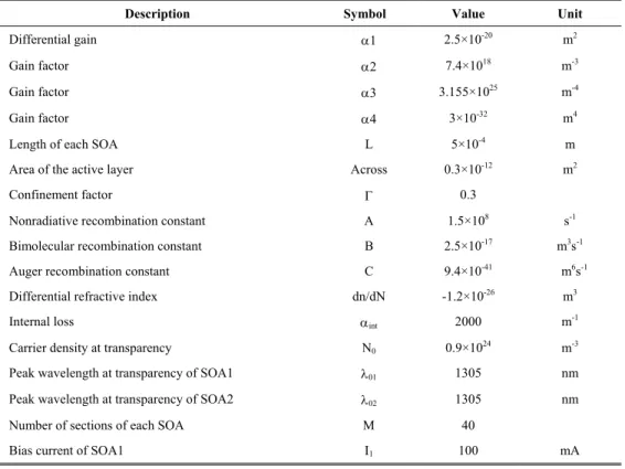
First, the sinusoidal-wave-modulated DFBLD was backward injected into the former SOA (driven at 72 mA) for loss modulation and the other, constant-gain, SOA (needed as the gain medium in the SOAFL) was driven by 142 mA. As the DFBLD power was increased from –1 dBm to 9.5 dBm, the mode-locked SOAFL pulse width shrank significantly, with its peak power increasing from 5 to 8 mW.
0 2 4 6 8 10 0 100 200 300 400 DFB Injection Power (dBm) P u ls e W idt h (p s) 5.0 5.5 6.0 6.5 7.0 7.5 8.0 Pe ak P o w e r (m W) 0 500 1000 1500 2000 0 2 4 6 8 10 DFB L D Pow er ( m W ) SO A FL Po we r ( m W ) Delay Time (ps) 0 2 4 6 8 10 12
Fig. 2. Temporal traces of measured pulse width and peak power versus detuning injection power.
Fig. 3. Experimental (solid curve) and simulated (dashed curve) pulse shapes of a SOAFL that is mode locked by a sinusoidal-wave-modulated DFBLD (dotted curve).
In principle, the mode-locking pulse width (tFWHM) is directly proportional to (g0)1/4/
(δ2· f
m2·∆ν2)1/4, where fm denotes the modulation frequency, ∆ν represents homogeneous
linewidth, g0 is single-pass integrated gain, and δ denotes the on-to-off modulation depth.
The insufficient backward-injection power from the DFBLD thus could not effectively deplete the gain of the SOA, which fails to induce sufficient modulation depth δ in the SOA for perfect mode locking. The threshold backward-injecting power required for initiating mode locking of the SOAFL at 1 GHz is 5.5 dBm, as illustrated in Fig. 2. Perfect mode locking of the SOAFL is achieved when the DFBLD injecting power increases to 9.5 dBm, producing a pulse width and a peak power of 29 ps and 8 mW, respectively. Figure 3 shows the measured and simulated pulse trains of the mode-locked SOAFL at a repetition frequency of 1 GHz. The mode-locked pulses build up at the moment of largest gain (corresponding to the time of lowest sinusoidal-wave injection power in the SOA). Reducing the DFBLD injecting power or increasing the SOA gain generally results in decreased gain depletion of the SOA, which is detrimental to the buildup of mode locking. Consequently, the mode-locking pulses are shifted significantly closer to the time of minimum DFBLD injection. Conversely, an increase of the DFBLD injection power (or a reduction of SOA gain) eventually leads to a shorter pulse width. Therefore, sufficient gain-depletion time (by enlarging the duty cycle of backward injection) and short gain-recovery time (by use of a SOA) are essential for mode locking the SOAFL.
0.50 0.75 1.00 0 10 20 30 40 1280 1290 1300 1310 1320 -60 -40 -20 In te n si ty (d B m ) Wavelength (nm) 5 GHz Pulsew idth (ps) fm-0.5 (GHz-0.5 ) 1 GHz 2 GHz 3 GHz 4 GHz 3GHz 1GHz 2GHz 2000 1600 1200 800 400 0 Time (ps) 0 400 800 1200 1600 2000 4GHz 5GHz
Fig. 4. Reciprocal frequency dependence of pulse width and corresponding spectrum of the SOAFL pulses repeated at 5 GHz.
Fig. 5. Pulse trains (black curves) and corresponding injection waveforms (gray curves) with repetition rates from 1 to 5 GHz.
Figure 4 shows the pulse width of the SOAFL mode locked at several repetition frequencies. The corresponding spectra of the modulated DFBLD and the mode-locked SOAFL at a repetition frequency of 5 GHz are shown in the inset. The mode-locking pulse #3846 - $15.00 US Received 19 February 2004; revised 8 April 2004; accepted 9 April 2004
shapes and the corresponding sinusoidal-wave-injection waveforms were also measured and are shown in Fig. 5. With the all-optical cross-gain-modulated SOA-based loss modulator, the shortest mode-locked pulse width recorded to date, 12 ps at a repetition frequency of 5 GHz, is reported for the first time to our knowledge. This pulse width is also shorter than those reported (21 ps) in similar systems in which pulsed-laser-diode-modulated SOAs were used [13]. Notably, a higher modulation power is essential for obtaining the same gain-depletion depth of the SOA at higher repetition frequencies, because the modulation bandwidth of the DFBLD used in this experiment is approximately 5 GHz. This limits the implementation of the proposed system to higher-harmonic frequencies. Reviewing these results reveals that the backward-injecting power is critical for the cross-gain-modulation-induced mode-locking technique and strongly affects the gain-depletion condition of the SOA.
4.2 Backward pulse injection
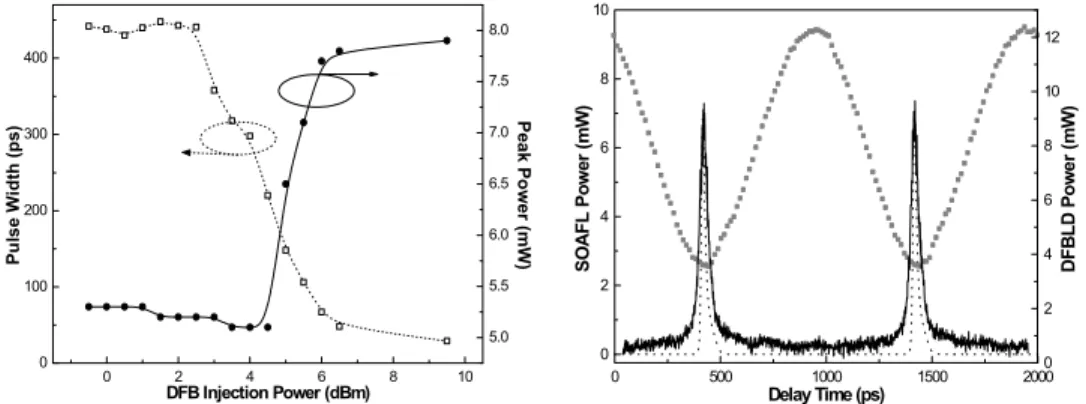
Optical pulse modulation has also been employed to periodically deplete the gain of SOAs. This is done by backward injection of the SOA with a gain-switched DFBLD pulse train (Fig. 6, dotted curve; tFWHM = 55 ps) that is neither amplified nor pulse compressed. The backward
injection of such a short optical pulse depletes only the gain of the SOA at a relatively narrow duration, leaving significant residual gain in the SOA within one modulating period. As a result, a mode-locked pulse is generated but contains a long pedestal in the falling part, which results fromthe excessive gain of the SOA in the remaining duty cycle. One cannot eliminate this nearly steady-state pedestal behind the mode-locked pulses, even by optimizing all the other system parameters. Additionally, significant relaxation oscillation is observed following the mode-locked pulse, in agreement with the theoretical simulation, as shown in Fig. 6. A characteristic frequency of 10 GHz for the SOA used in our system is also determined by fr = (1/2π)[(1/τnτp)(J/Jth – 1)]1/2, where τn and τp are the carrier and the photon
lifetimes, respectively, in the SOA, J represents the driving current density, and Jth is the
threshold current density of the SOA.
0 500 1000 1500 2000 0.0 2.0 4.0 6.0 8.0 SOAFL P o we r (mW ) Delay Time (ps) 0 4 8 12 16 DFBLD P o w e r (mW)
Fig. 6. Experimental (solid curve) and theoretically simulated pulse (dashed curve) shapes of a SOAFL that is mode locked by backward injection with a gain-switched DFBLD (dotted curve).
The theoretically simulated pulses have shorter pulse widths than the experimental pulses because the SOA gain is assumed to be fully depleted during the duration of pulsed injection, and the simulated gain constant of the SOA-based loss modulator is slightly smaller than the experimental constant. By comparison, the present implementation indicates that the SOAFL that is mode locked by a backward optical sinusoidal-wave-injected SOA exhibits a better mode-locking capability than that by a pulsed-injected SOA when the SOA is nearly transparent. This facilitates the generation of a pedestal-free mode-locking pulse from a SOAFL. Although the short DFBLD pulse helps to produce large gain depletion of the SOA in a short temporal duration, it is hard to achieve perfect mode locking if the gain-switched DFBLD power is insufficient (without amplification). To view the different pulse widths of a DFBLD at sinusoidal-wave-modulated and gain-switched DFBLD modes (500 and 50 ps,
respectively), one needs to determine a lower limit on the gain-depletion time for mode locking of the SOAFL (as we discuss in Subsection 4.4 below).
4.3 Effects of SOA gain and injection pulse-width detuning
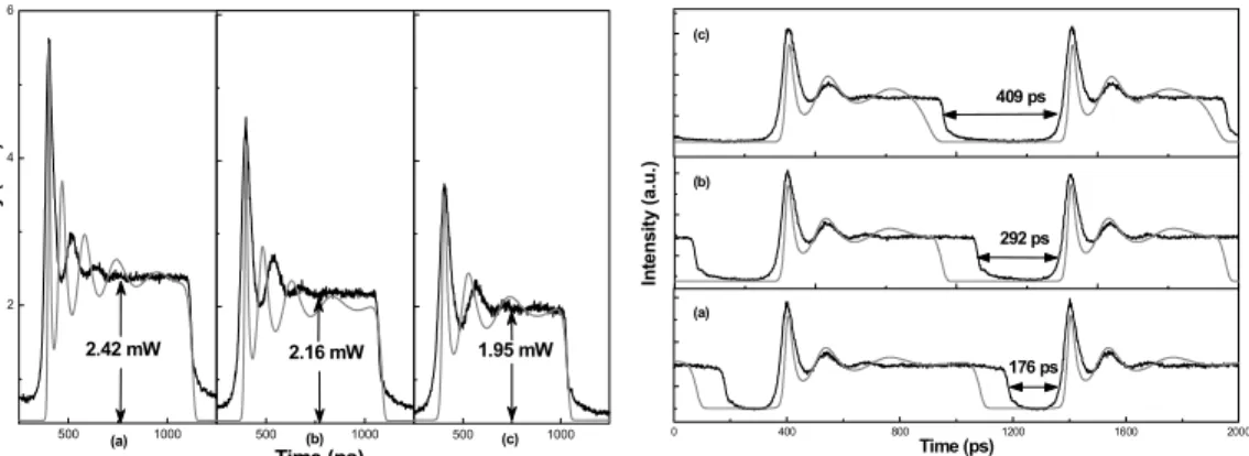
To further improve the mode-locked performance of SOAFLs we analyzed the effect of SOA gain and backward-injecting pulse-width detuning on the reduction in pedestal amplitude of a mode-locked SOAFL pulse. As the current of the SOA is detuned from 120 to 80 mA, one can suppress the pedestal amplitude by decreasing the driven current of the first SOA, which had been backward injection modulated by the gain-switched DFBLD (see Fig. 7). The pedestal is completely eliminated when the current of the SOA is decreased further to 65 mW. 500 1000 2 4 6 500 1000 500 1000 Intensity (mW) (a) 1.95 mW 2.42 mW 2.16 mW (b) Time (ps) (c) 0 400 800 1200 1600 2000 (a) Time (ps) In te ns it y ( a.u. ) 292 ps 176 ps (b) (c) 409 ps
Fig. 7. Darker curves, experimental pulse train with several injected SOA currents; lighter curves, simulated results.
Fig. 8. Darker curves, experimental pulse train with several injected linewidth pulses; lighter curves, simulated results.
Additionally, the smaller driven current of the SOA also helps to reduce the mode-locked SOAFL’s pulse width. The theoretical simulations coincide well with the present experiments, except for some deviations between the measured and calculated relaxation oscillation frequencies at different driven currents of the SOA. This deviation is attributed to the difference between the simulated and the real carrier densities in the SOA, which dominate the relaxation oscillation frequency. Nonetheless, these simulations have shown that the peak power of a gain-switched DFBLD with an extremely short pulse width must be sufficiently high to suppress the excessive gain of the SOA. Backward injection with a high-power gain-switched laser is also an alternative approach to pulse-width shortening. Otherwise, the duty cycle or the magnitude of the SOA gain must be reduced because backward injection of a low-power and short laser pulse is unavailable to consume the surplus gain in the SOA. Unfortunately, this approach simultaneously attenuates the peak power of mode-locked pulse. Therefore we realize that the backward-injecting pulse width has played an important role in the pulse shaping of a mode-locked SOAFL. Furthermore, theoretical analysis has demonstrated that the pedestal width is strongly correlated with the backward-injection pulse width. The pedestal of a mode-locked pulse disappears with the arrival of a DFBLD pulse, as shown in Fig. 8. As the pulse width of the DFBLD increases from 50 to 130 ps, an increase in the off state (from 176 to 409 ps) between adjacent mode-locked SAOFL pulses is experimentally observed. Notably, the deviation between the theoretically simulated and the experimentally determined results is attributed to the different shapes of the ideal Gaussian pulse (used for simulation) and the gain-switched DFBLD pulse. A sufficiently large pulse width of the backward injection thus is thus essential for inducing a sufficient gain-depletion window in a SOA for perfect mode locking.
4.4 Correlation between gain-depletion width and mode-locking performance
A novel experiment to determine the minimum gain-depletion width required for mode locking the SOAFL is demonstrated, which analyzes the SOAFL pulse trains generated by the backward injection of an optically digital–TTL pattern modulated DFBLD that uses different #3846 - $15.00 US Received 19 February 2004; revised 8 April 2004; accepted 9 April 2004
duty cycles. As illustrated in Fig. 9(a), the gain of a SOAFL is depleted when the optical word pattern from the DFBLD is in the on state, which subsequently recovers as the optical word pattern turns to the off state. The SOAFL can be mode locked only when the gain of the SOA overcomes the cavity loss of the SOAFL and resumes its maximum value. The gain recovery cannot be achieved once a strong gain-depletion is introduced by continuous on-state patterns, which eventually suppress or even destroy the mode-locking process. That is, mode locking starts up following the long-term recovery of the SOA gain while no patterns are injected. This phenomenon indicates that excessive gain depletion may also influence the gain recovery of the SOA and lead to imperfect mode locking. Nonetheless, a short gain-depletion time cannot produce a sufficient modulation depth to build up mode locking in a SOAFL. Meanwhile, the excessive gain depletion associated with shorter gain recovery time produces a sufficient modulation depth to inevitably destroy the mode-locking mechanism within one period, as can be seen from Fig. 9(b).
Pattern Generator DFBLD SOA Gain Mode-locked SOAFL 1 0 1 0 0 1 0 0 1 0 1 0 0 1 0 gain=a 0 Time(ps) Am pl it u d e ( a .u .) 0 1000 2000 0 500 1000 1500 2000 Time (ps) Am pl it ud e (a .u .)
Fig. 9(a). Output of the word pattern, the encoded DFBLD, the simulated SOA gain profile, and the mode-locked SOAFL.
Fig. 9(b). Experimentally encoded DFBLD output (top) and mode-locked SOAFL output (bottom).
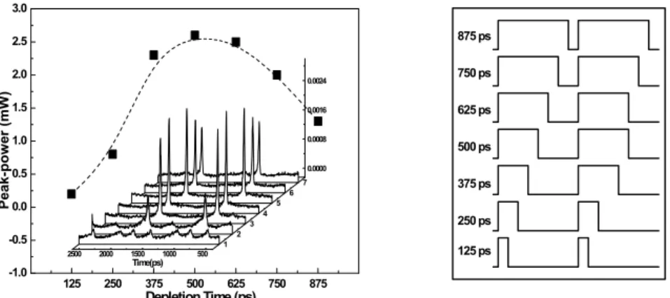
Experimentally, the period of the 1-GHz repetitive TTL pattern (which encodes the DFBLD) is sliced by use of various word patterns generated at 8 Gbits/s. This procedure causes the DFBLD’s pulse width to increase from 125 to 875 ps in increments of 125 ps. For example, the smallest width of the TTL-encoded DFBLD word pattern (10000000, 1-on–7-off) is 125 ps, as shown at the right in Fig. 10. Figure 10, left, shows variouspulse trains of a SOAFL that has been mode locked at the corresponding DFBLD (right) patterns with different duty cycles. Measuring the peak power of the mode-locked pulses reveals that the mode locking does not build up when the gain-depletion time is shorter than 250 ps because there is insufficient modulation (or gain-depletion) depth at such a low backward-injection power. A suitable range of 400–600 ps to obtain higher peak power in mode-locked pulses is suggested. The optimized gain-depletion time is 500 ps (11110000, 4-on–4-off) at a repetition frequency of 1 GHz, which correlates well with the result when a sinusoidal-wave-modulated DFBLD is used. As the gain of SOAFL becomes fully depleted during backward injection (the gain-depletion time approaches a full modulating period), the mode-locking mechanism of the SOAFL is destroyed. To initiate mode locking in such a backward- optical-injection-modulated SOAFL requires a gain-depletion width of >250 ps within a 1- GHz repetition period.
125 250 375 500 625 750 875 -1.0 -0.5 0.0 0.5 1.0 1.5 2.0 2.5 3.0 500 1000 1500 2000 2500 0.0000 0.0008 0.0016 0.0024 1 2 3 4 5 6 7 Time(ps) Peak-pow er ( m W ) Depletion Time (ps) 125 ps 750 ps 500 ps 625 ps 250 ps 375 ps 875 ps
Fig. 10. Left, trend traces of pulse widths with various depletion times from 125 to 875 ps; right, the corresponding injection word patterns.
5. Conclusions
The harmonic mode-locking dynamics of an optical backward-injection-modulated SOAFL has been investigated. The effects of gain-depletion time and modulation frequency on the mode-locked pulse shape and power have also been theoretically analyzed and experimentally demonstrated. It is much easier to use backward-sinusoidal-wave modulation than gain-switched modulation to initiate harmonic mode locking in a SOAFL, because the former generates pulse widths as short as 12 ps at 5 GHz. The effects of gain-depletion time and gain-recovery time on the buildup of the mode-locked SOAFL pulse-train have been elucidated, and the sinusoidal waveforms were found to be suitable for mode locking. The difficulty in mode locking a SOAFL by injection of an optical short pulse has also been demonstrated and explained; it was attributed to insufficient gain-depletion time (as well as to insufficient modulation depth). By reducing SOA current and increasing the pulse width of external injection, we theoretically fitted the mode-locked SOAFL pulses to interpret the origin of pulse degradation. The analytical results indicate that SOAFLs that are mode locked by optical backward-sinusoidal-wave- injected SOAs exhibit better mode-locking capability than does a pulse-injected SOA when the SOA is nearly transparent. The optical backward-sinusoidal-wave injection of a SOA also facilitates the generation of a pedestal-free mode-locked pulse from a SOAFL. To further analyze the buildup dynamics of the mode-mode-locked SOAFL with different gain-depletion times, we used a TTL-encoded DFBLD with various duty cycles for injection of the SOA. The minimum gain depletion time for starting the mode locking in a backward-optical-injected SOAFL was determined to be 250 ps. Finally, the optimized gain-depletion time required for mode locking the SOAFL was observed to be 400–600 ps.
Acknowledgments
The authors thank the National Science Council of the Republic of China, Taiwan, for financially supporting this research under contract NSC92-2215-E-009-028.