The electromagnetic shielding effectiveness of carbon
nanotubes polymer composites
Wern-Shiarng Jou
a,∗, Huy-Zu Cheng
b, Chih-Feng Hsu
aaDepartment of Mold Engineering, National Kaohsiung University of Applied Sciences, Kaohsiung, Taiwan bDepartment of Material Engineering, I-Shou University, Kaohsiung, Taiwan
Available online 6 October 2006
Abstract
The electromagnetic (EM) shielding effectiveness (SE) in plastics, of carbon nanotubes (CNTs) or multi-wall nanotubes (MWNTs) has been investigated. There are two kinds of CNTs with aspect ratio of 500 and 10,000 were added into a plastic as composites. The SE of both CNTs composites is higher than 40 dB, which is a requirement for industrial application. The two types MWNTs were compounded with two kinds of polymeric materials, such as liquid crystal polymers (LCPs) and melamine resins (MF). The highest SE of these composites was 60 dB which is realistic for an industrial application. It is noted that the higher the aspect ratio, the higher is the SE of nano-composites. The results of this study make the CNTs with effective EM shielding effectiveness that is suitable for use as electronic conductive fillers in plastic package.
Keywords: Carbon nanotubes; Electromagnetic wave; Shielding effectiveness; Composites; Aspect ratio; Orientation
1. Introduction
The large aspect ratio of carbon nanotubes (CNTs), unique tube-shape form and low density provide excellent electrical, mechanical and physical properties which are potentially suit-able for applications in polymer-based composites demanding anisotropic properties. The deformation affects the electrical properties of CNTs as well. In addition, the impurities[1](such as catalyst particles) enclosed by tubes during or after the grow-ing process may affect the electrical properties.
The polymer-based composites are popular in electronic appliance housings due to their light weight, low cost, high strength and easy processing. However, most polymeric mate-rials are transparent to EM radiation and provide no shield-ing against electromagnetic interference (EMI). In electronic and communication industries, the EMI pickups by electronic components raise serious problems such as noise enhance-ment and malfunction of electronic instruenhance-ments. Rapid devel-opment in optical communication industries demands optical components with high sensitivity, compactness and multiple functions. Therefore, EMI has become an important issue in optical–electronic packaging.
∗Corresponding author.
E-mail address:[email protected](W.-S. Jou).
Previous work done by the authors suggested several effec-tive solutions[2,3]. One solution is to modify the nylon66/liquid crystal polymers (LCPs) composites by adding short or long electrically conductive discontinuous carbon fibers (CFs) to build a three-dimensional conductive network within the poly-meric matrix. The alternative solution suggested by the author’s study[4]is to weave continuous carbon fibers (CCFs) compos-ites in pre-designed patterns provide continuously conductive network. Therefore, the content of CCFs can be largely reduced but the EM shielding of polymer composites can be remarkably enhanced. These newly developed techniques have been applied to optical transceiver modules[5–7].
Although, many EM shielding methods[2–10]are available for electronic plastic packaging, not many methods are avail-able for optical-electronic plastic packaging. Low cost, high EM shielding optical laser modules made with the modified ther-mosets using compression molding technology were reported
[5,11]. Instead of using compressing molding, a systematic investigation on the EM shielding effectiveness (SE) of nylon66 or LCP composites using injection molded thermoplastic pack-aging was conducted in the author’s previous work[2–4]. Kim reported a polymer-based composites with 40 wt% CNTs con-taining Fe catalysts can reach shielding effectiveness of 27 dB
[1]. The EM SE of composites with as grown CNTs are higher than those with purified CNTs because of presence of Fe metal particles. In his study, the authors synthesize the conductive
CNTs without using catalysts to avoid any attributes from metal catalysts. The content of CNTs is critical in the nano-composites since the cost of CNTs is much higher than most conductive fibers/fillers and engineering plastics such as nylon, LCPs, or epoxy. If the content of CNTs can be reduced, applications of such nano-composites can be economical. The CNTs prepared from the author’s laboratory consist of 25% pure MWNTs and 65% carbon nano-capsules (CNCs), carbonaceous impurities or ash and amorphous carbon. Previous work[3]has demonstrated that not only the SE of polymer composites can be improved, but also the content of CFs can be reduced by controlling the discontinuous CFs orientation.
The conductivity of composites can be changed from ductive to non-conductive over a narrow range of fillers’ con-centration, which primarily depends on the filler’s electrical characteristics. It has also been shown that if small conduc-tive fillers can be well dispersed to form a network within the composite, lower concentration of fillers will be required for conductive composites[1,2]. If both the polymer base and CNTs are in powder forms then the dispersion of CNTs will be insured in polymer base. Our previous work[2,3]showed that the higher the aspect ratio (the ratio of length to diameter) of fillers such as CFs, the higher is the SE of composites. Thus, the author would propose to use high aspect ratio conductive CNTs as a feasible way to reduce the CNTs’ content.
This study developed a CNTs polymer-based composite with high EM SE incorporated with the compression molding tech-nology. In the near future, it is anticipated to use the injection molding process for mass production such that the cost for pack-aging can be significantly reduced. The influences of the aspect ratio, orientation and the weight percentage of nano-materials, and the type of polymer materials upon the EM shielding of nano-composites were systematically studied.
2. Experiment
There are four different fillers, including CNTs synthesized by arc discharge (ADM) and CVD methods, amorphous car-bon (include some ash), and graphite powders in this study. The non-purified CNTs made by arc discharged method is denoted as CNTs–KUAS and the purified CNTs made by catalytically chemical vapor deposition method are obtained from the Desunnano Ltd. and is denoted as CNTs–Desunnano. Graphite powders are collected by grinding a carbon rod and nano-scaled amorphous carbon which are the side products of CNTs–KUAS. ADM generates a mixture of various car-bon products from which nanotubes must be separated. The aspect ratio of CNTs–KUAS is about 200–500 measured by SEM images and the CNTs–Desunnano is about 10,000 accord-ing to the specification from the Desunnano Ltd. The purity of CNTs–Desunnano is above 90% according to their specification. CNTs–Desunnano has been purified but the nano-scaled Fe cat-alysts are found inside the CNTs. However, the CNTs–KUAS are used as grown and are estimated to have 25% yield of CNTs, 10% of CNCs and 65% of amorphous carbon and ash.
The polymeric materials applied in this study are liquid crys-tal polymers (LCPs) and melamine formaldehydes (MF). The
LCPs exhibit a highly ordered structure in both the melt and solid states and are often applied to replace materials such as ceramics, metals, composites and other plastics, because of their outstanding strength at high temperature and their resis-tance to chemical resisresis-tance, weathering, radiation and flame. The MF is one of the amino thermoset resins and is formed by the condensation reactions of multi-functional monomers con-taining amine groups and formaldehyde. MF shows excellent appearance and physical properties and is compatible with a wide variety of fillers and is resistant to heat, acids and bases. All materials are in powder form for easy mixing and good dispersion.
A compression molding machine with temperature con-trollers was employed. The processing temperatures were set at 120–180 and 300–350◦C for MF and LCPs carbon materials filled composites, respectively. A compression molded circular specimen with the diameter of 133 mm and thickness of 1 mm was made as EMI specimen. An annual of 32 and 76 mm in inner and outer diameter was cut from molded circular specimen for measuring the EM SE.
The electric conductivity was measured by four-probe method. The measured conductivity was used to calculate the theoretical SE. The higher the SE value in decibel (dB) is, the less the energy passes through the sample. All measured SE is the combination of the EM radiation: reflection from the mate-rial’s surface, absorption of the EM energy and multiple internal reflections of the EM radiation[12]. There are two test systems that can be used to measure SE of composite samples[13]; a continuous conductor (coaxial) transmission-line device and an aperture-in-a-box system.
Plane-wave analysis[14]provides a good correlation with experimental measurements in terms of the relationship between the conductivity and the SE; therefore, a coaxial transmission
line technique based on the ASTM D4935 [15]method was
chosen to measure the SE of electrical conductive CNTs com-posites. The design and dimension of the coaxial sample holder measuring EM follows the ASTM method[2–4].
3. Results and discussion
Two kinds of CNTs with high aspect ratio and two carbon materials (amorphous carbon and graphite) with low aspect ratio were applied to investigate the effect of aspect ratio of car-bon material on the SE of polymer composites. In addition, to explore the orientation effect of carbon nano-materials on the SE of composites, two polymers (LCPs and MF) were utilized and compared in this study. The CNTs in the LCPs composite are more orderly than that in MF composite; thus, the SE of CNTs/LCPs composites is higher than that of CNTs/MF com-posites. This is consistent with the result shown in the authors’ previous work[3].
The morphology of CNTs is also an important factor affect the SE of CNTs composites. Two kinds of CNTs with different molecular structure were applied to determine the effect on SE. One is short, has less defects and is needle-like, the other is long, curvy and tangled with others. The mass fraction of carbon materials is another important factor. The mass fraction of CNTs,
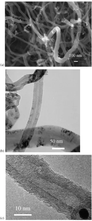
Fig. 1. Microstructure of CNT–Desunano: (a) SEM; (b) TEM; (c) HRTEM images.
amorphous carbon, and graphite in this study are 10, 20, 30, 40 and 50%.
The morphology of CNTs generated by different methods are examined by the scanning electron microscopy (SEM) as shown inFigs. 1(a) and 2(a), transmission electron microscopy (TEM) as shown inFigs. 1(b) and 2(b), and high resolution transmission electron microscopy (HRTEM) as shown inFigs. 1(c) and 2(c). The images of CNTs–Desunnano and CNTs–KUAS are shown as inFig. 1(a–c) andFig. 2(a–c), respectively.Fig. 1(a) shows that CNTs–Desunnano are curvy and tangled with each
Fig. 2. Microstructure of CNT–KUAS: (a) SEM; (b) TEM; (c) HRTEM images.
other. The CNTs–Desunnano are hollow cylindrical and the
CNTs–Desunnano are MWNTs as shown in Fig. 1(b and c),
respectively. Many impurities and defects are found in the CNTs–Desunnano such as Fe catalyst enclosed wihtin the CNTs, variation in inner diameter, and nodes on the tube. In addition, the diameter of CNTs–Desunnano varies from 40 to 120 nm. The inner diameter of CNTs–Desunnano is less than 10 nm but varied along the tube axis.
The CNTs–KUAS is needlelike sticking out of many hollow carbon nano-capsules (HCNCs) as shown inFig. 2(a).Fig. 2(b) illustrates that CNTs–KUAS are carbon nanotubes instead of
carbon nano-fiber. The CNTs–KUAS are also multi-layer car-bon nanotubes (MWNTs) as inFig. 2(c). Less defects are found in the CNTs–KUAS. They have none nodes and Fe catalyst enclosed within the CNTs and almost constant inner and outer diameters. The diameter of CNTs–KUAS varies from 8 to 20 nm corresponding to distribution in diameter narrower than that of CNTs–Desunnano. The inner diameter of CNTs–KUAS is less than 5 nm and is kept constant along the tube axis. In other words, the wall structure of CNTs–KUAS is better struc-turized and more crystalline like with less deformation than those of the CNTs–Desunnano. The length of CNTs–KUAS is normally shorter than that of CNTs–Desunnano. The aspect ratio of CNTs–KUAS is about 500, much less than that of CNTs–Desunnano. The latter is curvy but become aligned and less coiled after compounding with LCPs powder following the crystallization and orientation characteristics of LCPs.
All SE data presented here are averages of three test speci-mens and the standard deviation is less than± 1.0 dB, the error in the data is less than 3%. Electrical conductivity data are aver-ages of 10 test specimens and the error in these data is less than 10%. Error bars do not appear in plots because they are smaller than the symbols of data.
The electrical properties of carbon composites studied in this work include the conductivity and SE of carbon nanotubes composites. The electrical conductivity (EC) and SE of the com-posites for various mass fraction are shown as inFigs. 3 and 4, respectively. These results demonstrate that the aspect ratio of raw carbon materials is essential for conductivity and SE, since the high aspect ratio of raw material in composites would assist the construction of conductive network.
As shown in Fig. 3, the EC of CNTs–Desunnano/LCPs
composites are higher than that of CNTs–KUAS/LCPs. Based on the specification from Desunnano Co., the raw CNTs pur-chased has been purified, but some Fe catalysts have been enclosed in the raw CNTs as shown in the TEM micrograph ofFig. 1(c). The higher conductivities of CNTs–Desunnano or CNTs–Desunnano/LCPs composites are likely to be due to dif-ferent aspect ratio and Iron enclosed in CNTs.Fig. 3also reveals that the EC of CNTs–KUAS/LCPs composites were higher than
Fig. 3. Conductivity of LCP and MF nano-composites.
Fig. 4. SE of LCP and MF nano-composites.
that of CNTs–KUAS/MF composites. This finding reflects the highly ordering of LCPs molecules and CNTs. EC of graphite or graphite composites is lowest among all raw carbon materials or carbon composites. Since the conductive direction of graphite is in planes not on c-axis, it is difficult to make a three-dimensional conductive network.
Influence of mass fraction on SE values of carbon composites are shown as inFig. 4. The SE values of all carbon compos-ites increase with the weight percentage. The results indicate that LCPs orients the direction of CNTs and promote the SE of CNTs/LCPs composites.
Fig. 4also shows that the higher the aspect ratio, the larger is the difference in SE values between raw materials and poly-mer composites. This means that the effect of aspect ratio becomes more significant in carbon polymer composites. Com-parison of SE values of the two types of CNTs produced by different methods, SE values of CNTs–Desunnano/LCPs composites are higher than those of both CNTs–KUAS/LCPs and CNTs–KUAS/MF composites since the aspect ratio of CNTs–Desunnano is about 100 times higher. The SE values for both CNTs/LCPs composites are higher than those of graphite and amorphous carbon composites for all weight percentages since high aspect ratio CNTs form an oriented conductive net-work.
The polymer matrix effect can be understood by com-paring the SE values of CNTs–KUAS/LCPs composites and CNTs–KUAS/MF composites. The high ordering characteris-tics of LCPs and strong Van der Waal’s force between the CNTs and LCPs make the orientation effect significantly. The ori-entation effect on the EM SE has been reported in previous work [2,3]. Furthermore, the higher the aspect ratio of car-bon fiber (CF), the higher are the SE values of the CF filled polymer composites. In this study, the aspect ratio range of carbon nano-materials ranged widely, for example, the aspect ratio of CNTs–Desunnano, CNTs–KUAS and amorphous car-bon are larger than 10,000, about 500 and 1, respectively. The SE of CNTs–Desunnano/LCPs composites is higher than that of CNTs–KUAS/LCPs and CNTs–KUAS/MF composites because that the former is purified, have higher aspect ratio and contain
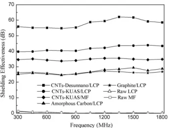
Fig. 5. Relations between SE and frequency for 50 wt% conductive carbon nano-materials filled LCPs and MF nano-composites.
Fe catalyst inside. The SE of graphite and amorphous carbon is the lowest among the raw carbon materials.
The SE of all 50% filled carbon composites versus
fre-quency is shown in Fig. 5. The SE of raw polymers (LCPs
and MF) is almost zero, that is, the raw LCPs and MF with-out any carbon materials are transparent to EM. The SE of CNTs–Desunnano/LCPs composites is the highest and almost 15 dB higher than that of CNTs–KUAS/LCPs composites at all frequencies. The SE of CNTs–KUAS/LCPs composites is significantly higher than that of CNTs–KUAS/MF com-posites at all frequencies due to the orientation effect of CNTs within the LCPs. The SE of amorphous carbon and graphite/LCPs composites is almost the same since their aspect ratio are similar. Finally, the highest SE value observed is 62.1 dB for CNTs–Desunnano/LCPs composites at frequency of 1.35 GHz.
The CNTs composites are suitable for the conventional injec-tion molding and compression molding process for mass pro-duction. A high SE nano-composite was developed to replace discontinuous CF composites in this study. According to the
result, the shielding effectiveness of the nano-composite is sim-ilar to that of conventional discontinuous carbon fiber (CF) filled polymer composites[2,3].
Acknowledgments
The authors would like to thank Dr. Chun-Lin Lu at Electri-cal Engineering Department, National Kaohsiung University of Applied Sciences, for using his EM SE measuring instruments. We also appreciate Desunnano Ltd. for supplying the CNTs. This work was partially supported by the National Science Council, Republic of China under contract NSC 94-2215-E-151-004.
References
[1] H.M. Kim, et al., Appl. Phys. Lett. 84 (4) (2004) 589. [2] W.S. Jou, J. Electron. Mater. 33 (3) (2004) 162.
[3] W.S. Jou, T.L. Wu, S.K. Chiu, W.H. Cheng, J. Electron. Mater. 31 (3) (2002) 178.
[4] W.S. Jou, T.L. Wu, S.K. Chiu, W.H. Cheng, J. Electron. Mater. 30 (10) (2001) 1287.
[5] W.H. Cheng, J.Y. Cheng, T.L. Wu, C.M. Wang, S.C. Wang, W.S. Jou, J. Lightwave Technol. 22 (9) (2004) 2177.
[6] T.L. Wu, W.S. Jou, W.C. Hung, C.H. Lee, C.W. Lin, W.H. Cheng, Electron. Lett. 40 (4) (2004) 260.
[7] T.L. Wu, W.S. Jou, S.G. Dai, W.H. Cheng, IEEE/OSA J. Lightwave Tech-nol. 21 (6) (2003) 1536.
[8] H. Mori, S. Tamura, A. Izawa, M. Iwase, OFC’99, San Diego, 198/ThN4-1, 1999.
[9] K. Tatsuno, K. Yoshida, T. Kato, T. Hirataka, T. Miura, K. Fukuda, T. Ishikawa, M. Shimaoka, T. Ishii, J. Lightwave Technol. 17 (1999) 1211. [10] M. Fukuda, F. Ichikawa, Y. Shuto, H. Sato, Y. Yamada, K. Kato, S. Tohno,
H. Toba, T. Sugie, J. Yoshida, K. Suzuki, O. Suzuji, S. Kondo, J. Lightwave Technol. 17 (1999) 1585.
[11] W.H. Cheng, J.Y. Cheng, T.L. Wu, C.M. Wang, S.C. Wang, W.S. Jou, Electron. Lett. 36 (2000) 118.
[12] L.X. Cheng, D.D.L. Chung, Compos. Part B: Eng. 30 (1999) 3. [13] M.R. Hantz, H.D. Newman, J. Appl. Polym. Sci. 16 (1972) 1249. [14] George Lubin (Ed.), Handbook of Composites, Van Nostrand Reinhold,
Co., 1982.
[15] Standard Testing Method for Measuring the Electromagnetic Shielding Effectiveness of Planner Materials, ASTM D4935-92, (ASTM, Philadel-phia, PA, USA).